Table of Contents
Advertisement
Quick Links
Advertisement
Table of Contents

Subscribe to Our Youtube Channel
Related Manuals for Xtool PS70PRO


Summary of Contents for Xtool PS70PRO
- Page 1 PS70PRO Diagnosis System User Manual...
- Page 2 Xtool will not bear any legal responsibility for that. 4. Xtool shall not be liable for any incidental or consequential damages or for any economic consequential damages arising from the accidents of individual users and...
-
Page 3: Table Of Contents
CHAPTERⅡ How to use PS70PRO ................5 1.PS70PRO Activation ....................5 1.1. Please activate PS70PRO before you use it to test vehicles ......... 5 1.2. Connect to WiFi first .................... 5 2. PS70PRO Main Interface and Functional Buttons Descriptions ....... 6 2.1. -
Page 4: Chapterⅰ About Ps70Pro
PS70PRO Diagnosis System CHAPTERⅠ About PS70PRO 1. Appearance 1.1. Front View 1.2. Back View... -
Page 5: Layout Of Ps70Pro Tablet
PS70PRO Diagnosis System 2. Layout of PS70PRO Tablet ① ② ③ ①MicroUSB: Battery charge or data synchronization with PC ②DB15 Port: Supports wired connection with car by the cable ③Power Button: Power on or power off 3. PS70PRO Technical Parameters... -
Page 6: Chapterⅱ How To Use Ps70Pro
PS70PRO Diagnosis System CHAPTERⅡ How to use PS70PRO 1. PS70PRO Activation 1.1. Please activate PS70PRO before you use it to test vehicles. 1.2. Connect to WiFi first. Please fill in the company name and mailbox, then click OK to complete the activation. -
Page 7: Ps70Pro Main Interface And Functional Buttons Descriptions
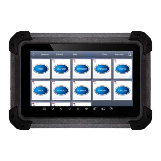
PS70PRO Diagnosis System 2. PS70PRO Main Interface and Functional Buttons Descriptions 2.1. Main Interface Tap on PS70PRO application, the main interface and sub-menus show up as below.▼ 2.2. Sub-menus and Function Buttons Function Buttons Descriptions Configures PS70PRO Tablet to perform as diagnosis system. -
Page 8: Toolbar Function Buttons
Turn on PS70PRO tablet b. Connect cables and PS70PRO in following order: ①→②→③→④ c. Switch on the ignition and tap on PS70PRO application to test vehicles. (Shown as follows) ① PS70PRO Mainframe ② Main Test Cable ③ OBDⅡ-16 ④ Vehicle... -
Page 9: Precautions Before Use
Users should cancel the task and return to the main interface, then power off. 3.2.8. The device should be put and lifted slightly to avoid collision when using PS70PRO. When click the screen, touch it gently to guarantee the service life of the touch screen. -
Page 10: Diagnosis
PS70PRO Diagnosis System 4.Diagnosis 4.1. Menu Options 4.1.1. After PS70PRO tablet connected to vehicle via main cable, diagnosis can be performed now. The diagnostic interface comes up as below. 4.1.2. Users can choose menu based on their actual needs: selection for Europe... -
Page 11: Test Functions
PS70PRO Diagnosis System 4.2. Test Functions 4.2.1. Take Volkswagen car for example, select Diagnosis, then select Europe Car, users can see Volkswagen’s VW word. If the VW word has not been seen, please swipe up and down or enter the car model to research. - Page 12 Actuation/Active/ Components Test: mainly to judge whether these actuating components of engine are working properly. 4.2.2. Toolbar function buttons descriptions Function Buttons Descriptions Returns to previous interface Print testing data Click it to record the data, click again to send your feedbacks to XTOOL after service center...
-
Page 13: Read Ecu
PS70PRO Diagnosis System Record data feedback button as shown below, showing diagnostic software version and various information in the diagnostic process. 4.3. Read ECU This function is to read ECU version information, which is the equivalent of “System Identification” or “System Information” in some electronic control systems, all mean... -
Page 14: Read Dtcs
PS70PRO Diagnosis System 4.4. Read DTCs Select Read Fault Codes to read trouble codes stored in ECU. Screen will show the trouble code and its definition when read the trouble codes, shown as below. Tip: In the process of diagnosis, if the device shows “System is OK” or “No Trouble Code”, it means there is no related trouble code stored in ECU or some troubles are... -
Page 15: Read Live Data
PS70PRO Diagnosis System 4.5.2. Click YES to make clear confirmation, if the communication is normal, it will show “Trouble Codes Successfully Cleared” or “Trouble Codes Cleared”. Generally, users need re-read trouble codes after cleaning them to confirm whether the trouble codes have been cleared. - Page 16 PS70PRO Diagnosis System Tips: Live Data is the important function for maintenance technicians further diagnose the troubles. This function needs maintenance technicians to be very familiar with sensor data of each system, control signals and control modes, all which are the indispensable basis of using Live Data function for maintenance technicians.
- Page 17 PS70PRO Diagnosis System Display Modes There are two modes to view Live Data, users can choose optimum mode according their own needs and different parameter types. Dashboard Mode: Display parameters in the form of simulating instrument graphics. Graph Mode: Display parameters in the form of graph.
-
Page 18: Special Functions
PS70PRO Diagnosis System 4.7. Special Functions More special functions will be found in different vehicle models. 4.8. Actuation/Active/Components Test Test Conditions: Ignition on engine off. If engine started or rotation speed signal recognized, actuating component diagnosing will be interrupted. In the process of actuating components diagnosis, single component will always be in the trigger status until the next component being activated. - Page 19 PS70PRO Diagnosis System 4.8.1. Return to Dynamic Diagnostic Data, enter Actuating Components Test and it will show the menu of the actuating components that carry out action test, shown as below. Tip: Actuating Components Test performs function tests for parts of system actuating components.
-
Page 20: Settings
PS70PRO Diagnosis System 5. Settings Click Settings: users can set the language, unit and other system related options. Languages: select the language. Please tick the needed option from multi-language options on the right. Units: Select unit of measurement. Users can tick Metric or English measurement. -
Page 21: Diagnostic Reports
PS70PRO Diagnosis System 6. Diagnostic Reports Diagnostic Reports is for checking the saved files, such as the report of Live Data or Trouble Codes or pictures generated in the process of diagnosis, users also can know what cars have been tested. It includes three parts: PDF Files, Pictures and Data Playback. -
Page 22: Pictures
Data Playback can check what cars have been tested and play recorded Live Data & freeze frame. 7. Update PS70PRO doesn’t need insert a card for updating, users only need to tap on PS70PRO application and click Update , shown as follows. -
Page 23: Xtool Cloud System(Coming Soon)
All the auto maintenance technicians who use our products can not only look up the maintenance information that we put on our cloud service platform conveniently, and combine the diagnosis result to query, and communicate with other Xtool users in our forum, but can also access various online databases of maintenance and diagnostic skills and vehicle maintenance plans. -
Page 24: Chapterⅲ Diagnostic Link Connectors Of Different Vehicle Models
PS70PRO Diagnosis System CHAPTERⅢ Diagnostic Link Connectors of Different Vehicle Models 1. Diagnostic Link Connectors Diagram of Some Vehicle Models *AUDI A6: the OBD plug is on the lower left side of the dashboard, we can use SMART OBDII-16 connector. - Page 25 PS70PRO Diagnosis System *Benz C180: the OBD plug is in the right back side of engine room,we can use Benz-38 connector. *Benz 300SEL 140 chassis: the OBD plug is in the right side of the engine room,we can use Benz-38 connector.
- Page 26 PS70PRO Diagnosis System *GM Buick GL8 : the OBD plug is below the dashboard,we can use SMART OBDII-16 connector. *VW POLO: the OBD plug is below the dashboard; we can use SMART OBDII-16 connector. *BMW 735I: the OBD plug is in the left side of the engine room, we can use BMW-20...
-
Page 27: Location Diagram Of Vehicle Diagnostic Link Connectors
PS70PRO Diagnosis System *VW Passat B5: the OBD plug is behind the gearlever and beside the parking brake lever. It will appear when take away the cover. we can use SMART OBDII-16 connector. 2. Location Diagram of Vehicle Diagnostic Link Connectors... -
Page 28: Diagnostic Link Connectors Terminal Definition And Communication Protocols
PS70PRO Diagnosis System Link diagram of small car diagnostic link connectors: NOTE: Each vehicle manufacturer may use additional pins to diagnose a variety of systems. Not every manufacturer uses the same standard. The function on a certain pin will vary from manufacturer to manufacturer. Verify with the manufacturer. - Page 29 PS70PRO Diagnosis System Pin Definition (Reference material) Various pin definitions as follows: 1. Manufacturer definition 2. SAE J1850 bus positive 3. Manufacturer definition 4. Bodywork site 5. Signal site 6. ISO 15765-4 defined CAN high 7. ISO9141 and ISO14230 defined K line 8.
- Page 30 FCC Statement This device complies with part 15 of the FCC rules. Operation is subject to the following two conditions: (1) this device may not cause harmful interference, and (2) this device must accept any interference received, including interference that may cause undesired operation. Changes or modifications not expressly approved by the party responsible for compliance could void the user's authority to operate the equipment.
Need help?
Do you have a question about the PS70PRO and is the answer not in the manual?
Questions and answers