
Related Manuals for WAGO 852-1322


Summary of Contents for WAGO 852-1322
- Page 1 Industrial Managed Switch 8 Ports 1000BASE-T; MAC Security 852-1322 Product manual | Version 1.2.0...
- Page 2 We wish to point out that the software and hardware terms as well as the trademarks of companies used and/or mentioned in the present manual are generally protected by trademark or patent. WAGO is a registered trademark of WAGO Verwaltungsgesellschaft mbH. Product manual | Version: 1.2.0 Industrial Managed Switch...
-
Page 3: Table Of Contents
852-1322 Table of Contents Table of Contents Provisions......................... 6 Proper Use ...................... 6 Typographical Conventions.................. 7 Legal Information .................... 8 Safety .......................... 10 General Safety Regulations .................. 10 Electrical Safety..................... 10 Mechanical Safety .................... 11 Indirect Safety ....................... 12 Overview ......................... 13 Properties ........................ 14 Views........................ - Page 4 Table of Contents 852-1322 6.1.1 Installation Site ..................... 24 Transport and Storage.................... 25 Installation and Removal.................... 26 Installation ...................... 26 8.1.1 Installation on a Carrier Rail ................. 26 Removal ........................ 26 8.2.1 Removal from Carrier Rail ................ 26 Connection ........................ 27 Grounding...................... 27 Connecting the Supply Voltage ................
- Page 5 852-1322 Table of Contents 10.6.3.2 Parameters Setting (IEEE 802.1X - Parameter Setting)...... 63 10.6.3.3 Port Setting (IEEE 802.1X - Port Setting).......... 64 10.6.4 Port Security .................... 65 10.6.5 VLAN ...................... 67 10.6.5.1 Port Isolation.................. 67 10.6.5.2 VLAN Setup .................. 68 10.6.5.3 Management VLAN ................ 70 10.7 Redundancy ......................
-
Page 6: Provisions
The terms set forth in the General Business & Contract Conditions for Delivery and Ser- vice of WAGO Kontakttechnik GmbH & Co. KG and the terms for software products and products with integrated software stated in the WAGO Software License Contract – both ü www.wago.com... - Page 7 852-1322 Provisions 1.2 Typographical Conventions Number Notation Decimals: Normal notation 0x64 Hexadecimals: C-notation ‘100’ Binary: In single quotation marks ‘0110.0100’ Nibbles separated by a period Text Formatting italic Names of paths or files bold Menu items, entry or selection fields, emphasis...
-
Page 8: Legal Information
Third-party products are always mentioned without any reference to patent rights. WAGO Kontakttechnik GmbH & Co. KG, or for third-party products, their manufacturer, retain all rights regarding patent, utility model or design registration. - Page 9 – excepting change or improvement performed under guarantee agreement – are excluded. Licenses The products may contain open-source software. The requisite license information is saved in the products. This information is also available under ü www.wago.com. Product manual | Version: 1.2.0 Industrial Managed Switch...
-
Page 10: Safety
In addition, ensure that any supplement to this documentation is included, if necessary. • Any actions related to the use of WAGO software may only be performed by qualified staff with sufficient knowledge to use the respective PC system. -
Page 11: Mechanical Safety
• For industrial use: WAGO's 852 Series ETHERNET Switches are certified to be used in residential and in industrial environments. If the latter, they should be considered as exposed operating components. -
Page 12: Indirect Safety
• Before installation and operation, please read the product documentation thoroughly and carefully. In addition, note the information on the product housing and further infor- mation, e.g. at ü www.wago.com/<item number>. • Change the password. The factory default setting is widely known and does not pro- vide adequate protection. -
Page 13: Overview
And because MACsec encryption is hardware-based, there is no name- able added latency. WAGO’s 852-1322 is ideal for adding an extra layer of security in residential and indus- trial applications that require compact solutions while delivering high network perfor- mance up to 97 % of throughput guaranteed with no nameable additional latency. -
Page 14: Properties
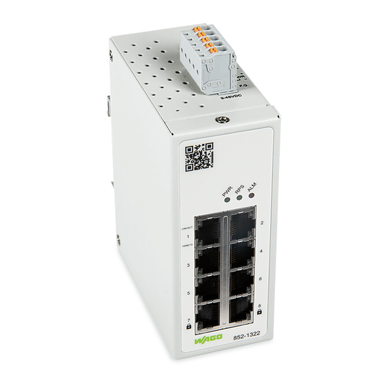
Properties 852-1322 Properties 4.1 Views 4.1.1 Front View Figure 1: Front View of the Industrial Managed Switch Product manual | Version: 1.2.0 Industrial Managed Switch... -
Page 15: Top View
852-1322 Properties Table 1: Legend for the Figure "Front View of the Industrial Managed Switch" Pos. Custom Name Explanation Status LED Power input 8 Display Elements [} 18] Status LED redundant input 8 Display Elements [} 18] Status LED alarm 8 Display Elements [} 18] RJ-45 ports (10/100/1000BASE-T(X)) 8 Port LEDs [} 19]... -
Page 16: Label
Properties 852-1322 4.2 Label Figure 3: Label Table 3: Legend for Figure „Label“ Custom Name Description Item-No Item number Device input and maximum current and voltage Ambient Temp Device input and maximum current and voltage Device MAC information Default IP Device default IP address... -
Page 17: Network Connections
852-1322 Properties Figure 5: Power Supply Connector Table 4: Legend for Figure “Power Supply" Connection Custom Name Description Secondary DC input ‑ Secondary DC input Primary DC input Primary DC input F.G. Functional Ground NOTICE Damage to Property Caused by Electrostatic Discharge (ESD)! DC Powered Switch: Power is supplied through an external DC power source. -
Page 18: 10/100/1000Base-T(X) Ports
Properties 852-1322 Pos. Description For Details, see Section: 2 x SFP connections 8 10/100/1000BASE-T(X) (MACsec) ports [} 18] (10/100/1000BASE-T(X) (MACsec) 4.3.3.1 10/100/1000BASE-T(X) ports 10/100/1000BASE-T(X) ports support networks speeds of 10 Mbit/s, 100 Mbit/s und 1000 Mbit/s and can be operated in half- and full-duplex transmission modes. These ports also provide automatic crossover detection (Auto-MDI/MDI-X), with plug-and-play capabilities. -
Page 19: Port Leds
852-1322 Properties 4.4.2 Port LEDs Figure 8: Port LEDs Table 7: Legend for „Port LEDs“ Figure Connection Status Description LINK/ACT 10/100/1000 BASE T Ports LED Green Port in operation (1 LED for each port) Flashes Data traffic routed via the port No proper link established... -
Page 20: Environment Requirements
Ordinary Locations UL62368 (E482462) Note More information on approvals You can find detailed information on the approvals online at: ü www.wago.com/<item number> 4.6.2 Regulations and Standards Please observe the standards and regulations that are relevant to installation: Product manual | Version: 1.2.0... - Page 21 852-1322 Properties • The data and power lines must be connected and installed in compliance with the stan- dards to avoid failures on your installation and eliminate any danger to personnel. • For installation, startup, maintenance and repair, please observe the accident preven- tion regulations of your machine (e.g., DGUV Regulation “Electrical Installations and...
-
Page 22: Functions
• Authentication Server: This server performs the actual authentication. We utilize RA- DIUS („Remote Authentication Dial-In User Service“ as the authentication server. • Authenticator: The Authenticator is a network device (i.e. the WAGO Industrial man- aged switch) that acts as a proxy between the supplicant and the authentication server. -
Page 23: Mac Security (Macsec)
Functions 5.1.3 MAC Security (MACSec) WAGO industrial managed switches support advanced security features that allow traffic encryption and high throughput. MACsec or Media Access Control Security is a security standard specified by IEEE also called IEEE 802.1AE. This IEEE MAC security standard provides connectionless user data confidentiality, frame data integrity, and data origin au- thenticity. -
Page 24: Planning
Planning 852-1322 Planning 6.1 Structure Guidelines 6.1.1 Installation Site The location selected to install the may greatly affect its performance. When selecting a site, we recommend considering the following rules: 8 Environment requirements [} 20] • Install the at an appropriate place. See Section for the acceptable temperature and humidity operating ranges. -
Page 25: Transport And Storage
852-1322 Transport and Storage Transport and Storage The original packaging offers optimal protection during transport and storage. • Store the product in suitable packaging, preferably the original packaging. • Only transport the product in suitable containers/packaging. • Make sure the product contacts are not contaminated or damaged during packing or unpacking. -
Page 26: Installation And Removal
Installation and Removal 852-1322 Installation and Removal 8.1 Installation 8.1.1 Installation on a Carrier Rail The carrier rail must optimally support the EMC measures integrated into the system and the shielding of the internal data bus connections. Place the onto the DIN rail from the top and snap it into position. -
Page 27: Connection
852-1322 Connection Connection 9.1 Grounding Grounding is through the grounding screw on the top of the product. The switch must be grounded. Connect the grounding screw to the ground potential. Do not operate the switch without an appropriately installed protective earth conductor. - Page 28 Connection 852-1322 1. Connect one end of the twisted pair cable of the type Category 3/4/5/5e to an avail- able RJ-45 port on the and the other end to the port of the selected network node. 2. Check the respective port LED on the that the connection is established (see Section 8 Port LEDs...
-
Page 29: Configuration In The Wbm
852-1322 Configuration in the WBM Configuration in the WBM An internal file system and integrated Webserver can be used for configuration and ad- ministration of the system. Together, they are referred to as the Web-Based Management (WBM) system. The HTML pages saved internally provide you with information about the configuration and status of the industrial managed switch. - Page 30 - Please, click on the red box [Advanced] button and click on [Accept the Risk and Continue] button. Figure 11: Security Warning Page 6. After pressing the [Enter] key. Figure 12: WAGO Login Page 7. Enter your user name and password in the query dialog: Username = „admin“ Password = „wago“...
-
Page 31: Table 13: Overview - Navigation Links And Wbm Pages
852-1322 Configuration in the WBM Figure 13: Start Page of WBM 9. Select your desired page on the navigation bar at the top of the screen and clicking on corresponding tab on the left hand side of the screen. 10. Make the desired settings on the desired web page. -
Page 32: Login Failure
Configuration in the WBM 852-1322 Navigation Links and WBM Pages [Diagnostics] • SNMP ® • Modbus • System-Log • Port Monitor [Security] • Static SAK • Secure Code • 802.1X (IEEE 802.1X) • Port Security • VLAN [Redundancy] • RSTP [Maintenance] •... - Page 33 852-1322 Configuration in the WBM Figure 15: Login Failure Dialog Figure 16: Login Failure Dialog with only [Forget it] button If you click on the [Forget it] button, the device will randomly ask for a secure code of three characters. The three characters are randomly chosen from the security card. You will need to look up the characters in the security card and use them to enter them in the Secure code textbox as shown in Figure “Example of Dialog after Clicking [Forget it] But-...
- Page 34 Figure “Re-direction to Change Password Tab Page”. When you finished changing the new password, click on the [Submit] button. The system will prompt you with the WAGO login page to enter the new password as shown in Figure “WAGO Login Dialog after Resetting Password”.
-
Page 35: Information
To help users become familiar with the device, the System Information tab page provides important details of the WAGO’s industrial managed switch. This is also the main wel- come screen once the user has logged in. The details make it easier to identify different switches connected to the network. -
Page 36: Legal Information
Configuration in the WBM 852-1322 10.3.2 Legal Information This page has two tabs that are WAGO Licenses and Open Source Licenses. They list all information and terms about software license agreement. Wago Licenses Figure 22: WBM “Information” Page – “Legal Information” – “WAGO Licenses” Tab Open Source Licenses Figure 23: WBM “Information”... -
Page 37: Device Discovery - Lldp
852-1322 Configuration in the WBM page of the product. Table “WBM “Configuration” Page – “System Settings” Tab” summa- rizes the device information setting descriptions and corresponding default factory set- tings. Figure 24: WBM “Configuration” Page – “System Settings” Tab Table 15: WBM “Configuration” Page – “System Settings” Tab... -
Page 38: System Management - Sntp
Configuration in the WBM 852-1322 Figure 25: WBM "Configuration" tab – "LLDP Settings" page Table 16: WBM "Configuration" tab – "LLDP Settings" page Parameter Description Enable State Select Enable State to enable LLDP on the switch. Deselect Enable State to dis- able LLDP on the switch. Remember to click on the [Submit] button to confirm your choice. -
Page 39: Sntp Setup
852-1322 Configuration in the WBM • If the switch does not receive an SNTP reply packet, it repeats the challenge every ten seconds. • If the switch receives an SNTP reply, it repeats the time request from the NTP server every hour. - Page 40 Configuration in the WBM 852-1322 Parameter Description Time Select the time in the format hour/minute/second that you are manually setting for the system. Daylight Saving Settings Enable State Select Enable to enable Daylight Saving Settings or Disable to disable Daylight Saving Settings.
-
Page 41: Network Settings
10.4.4 Network Settings In this tab page, users may modify network settings of Internet Protocol version 4 (IPv4) for the WAGO industrial managed switch. The Network Settings tab page is depicted in Figure “WBM “Configuration” Page – “Net- work Settings” Tab”. Inside the Network Settings box, the user can enable Dynamic Host Configuration Protocol (DHCP) client inside the switch by checking the DHCP box so that the switch can obtain IP address’... -
Page 42: Port Settings
Configuration in the WBM 852-1322 Figure 28: WBM “Configuration” Page – “Network Settings” Tab The description of each parameter and its default value in Network Settings tab page are summarized in Table “WBM “Configuration” Page – “Network Settings” Tab”. Table 19: WBM “Configuration” Page – “System Settings” Tab... -
Page 43: Interface - Port Mirroring
852-1322 Configuration in the WBM Figure 29: WBM “Configuration” Page – “Port Settings” Tab The description of each parameter and its default value in Port Settings tab page are summarized in Table “WBM “Configuration” Page – “Port Settings” Tab”. Table 20: WBM “Configuration” Page – “Port Settings” Tab“... -
Page 44: Port Mirroring Setup
Select the port to which the network traffic of the source port should be copied 10.4.7 Password User name “admin” and password “wago” are set for the device when it is manufactured. The user can modify the device’s user name and password to ensure overall system se- curity. -
Page 45: Diagnostics
User name to log-in with maximum length of 15 characters. Password wago Password to log-in with maximum length of 15 characters. Confirmed Password wago Re-type the password. This has to be exactly the same as the password entered in the above field with maximum length of 15 characters. -
Page 46: Snmp Agent
SNMPv3 is enabled, the “Communities” of SNMPv1 and v2c have to be unique and can- not be shared. WAGO’s industrial managed switch support SNMP and can be configured in this tab page as shown in Figure “WBM “Diagnostics” Page – “SNMP” Tab”. The SNMP setting has four parts, which are: •... - Page 47 852-1322 Configuration in the WBM Figure 32: WBM “Diagnostics” Page – “SNMP Setting Part 1” Tab Product manual | Version: 1.2.0 Industrial Managed Switch...
- Page 48 Configuration in the WBM 852-1322 Figure 33: WBM “Diagnostics” Page – “SNMP Setting Part 2” Tab Product manual | Version: 1.2.0 Industrial Managed Switch...
- Page 49 [Submit] button as shown in Figure “SNMP Agent Setting”. The SNMP version 1 (V1), version 2c (V2c) and version 3 are supported by WAGO’s managed switches as summarized in “WBM Page, “Diagnostics” – “SNMP” Tab, SNMP Agent Setting”Fehler! Verweisquelle konnte nicht gefunden werden..
-
Page 50: Table 23 Wbm Page, "Diagnostics" - "Snmp" Tab, Snmp Agent Setting
SNMP V3, if possible. There are two levels of authentications or permission type in WAGO 852-1322, which are read-all-only or read-write-all. For exam- ple, in our default setting as shown in Figure “SNMP V1/V2c Community Setting”, an... -
Page 51: Table 24 Wbm "Diagnostics" Page - "Snmp" Tab, Snmp V1/V2C Community Setting
852-1322 Configuration in the WBM Figure 36: SNMP V1/V2c Community Setting Table “WBM “Diagnostics” Page – “SNMP” Tab, SNMP V1/V2c Community Setting “briefly provides descriptions of SNMP V1/V2c community string setting. Table 24: WBM “Diagnostics” Page – “SNMP” Tab, SNMP V1/V2c Community Setting... -
Page 52: Table 25 Wbm "Diagnostics" Page - "Snmp" Tab, Snmp Trap
Configuration in the WBM 852-1322 Figure 37: WBM “Diagnostics” Page – “SNMP” Tab, SNMP Trap The SNMP Trap Mode allows users to configure SNMP Trap mode or Inform mode by se- lecting the desired mode from the dropdown list as shown in Figure WBM “Diagnostics”... -
Page 53: Snmp-V3-Auth
852-1322 Configuration in the WBM Parameters Factory Default Description Community String Null Enter the community string for authentication. The maximum length of the string is 15 characters. 10.5.1.4 SNMP-V3-Auth. As mentioned earlier, SNMP V3 is a more secure SNMP protocol. In this part, the user will be able to set a password and an encryption key to enhance the data security. -
Page 54: Modbus Tcp
Re-entering the Encryption Key to confirm. 10.5.2 Modbus TCP WAGO’s industrial managed switch can be connected to a Modbus network using Mod- bus TCP/IP protocol which is an industrial network protocol for controlling automation equipment. The switch’s status and settings can be read through Modbus TCP/IP proto- col which operates similar to the Management Information Base (MIB) browser. -
Page 55: System-Log
852-1322 Configuration in the WBM Figure 39: WBM “Diagnostics” Page – “Modbus TCP” Tab To set a Modbus Address for the industrial managed switch, choose a number from 1 to 247 and enter it in the Modbus Address field. Click [Submit] button to configure it. To en-... -
Page 56: Table 28 Wbm "Diagnostics" Page - "System Log" - "Setting" Tab
Configuration in the WBM 852-1322 dustrial managed switch and/or it can be sent to a remote log server. The user needs to select the log level and provides the IP address of a remote log server and the service port of the log server. Please click on the [Submit] button after finishing the setup. Table “WBM “Diagnostics”... -
Page 57: Log
852-1322 Configuration in the WBM 10.5.3.2 Log The Log tab page under the System Log as shown in Figure “System Log Page” can dis- play the log information based on the log level configured in the System Log Setting tab page (previous subsection). -
Page 58: Table 29 Wbm Page, "Diagnostics" - "System Log" - "Log" Tab
Configuration in the WBM 852-1322 Figure 42: [Start] Button is visible when Automatic refresh cycle is enabled. Table 29: WBM Page, “Diagnostics” – “System Log” – “Log” Tab Parameters Factory Default Description Read all notifications Selected Activate the display of all log messages. -
Page 59: Port Monitor
Port monitor tab page is shown in Figure “WBM “Diagnostics” Page – “Port Monitor” Tab”. It depicts the actual connecting status for all available ports of the WAGO industrial man- aged switch in this page. The user can see that status whether a port is connected (Link Up/ Green color) or disconnected (Link Down/ Yellow color) or disabled (Black color). -
Page 60: Security
Figure WBM Page, “Security” – “Static SAK” Tab shows the “Static Secure Association Key” (SAK) settings tab. Please note that WAGO 852-1322 supports the MACsec proto- col on ports 7 and 8. To enable secure association mode on industrial managed switch’s port(s), first select one of the two ports from the dropdown list under the Ports. -
Page 61: Secure Code
0s. 10.6.2 Secure Code Every WAGO industrial managed switch will have eight secure codes. Every code has three characters. The security codes of every switch are unique. An example of secure code is illustrated in Figure “Example of Secure Codes”. They can be used to log in to the industrial managed switch when the user forgot the password and selected the [Forget it] button at the login dialog. -
Page 62: Setting (Ieee 802.1X - Setting)
Configuration in the WBM 852-1322 Figure 47: WBM “Security” Page – “802.1X” Tab 10.6.3.1 Setting (IEEE 802.1X - Setting) The 802.1X security mechanism can be enabled in this tab page as shown in Figure “WBM “Security” Page – “802.1X” – “Setting” Tab. When the user checks the Enabled box, the rest of the option fields will become active. -
Page 63: Parameters Setting (Ieee 802.1X - Parameter Setting)
852-1322 Configuration in the WBM Figure 48: WBM “Security” Page – “802.1X” – “Setting” Tab Table 33: WBM “Security” Page – “802.1X” – “Setting” Tab Parameters Factory Default Description 802.1x Disabled Choose to Enable/Disable 802.1X for all ports. Radius Server IP 0.0.0.0 Set an IP address of the RADIUS server. -
Page 64: Port Setting (Ieee 802.1X - Port Setting)
30 to 65535 seconds. 10.6.3.3 Port Setting (IEEE 802.1X - Port Setting) The user can configure the 802.1x security mechanism on each port of the WAGO secure switch as shown in Figure “WBM “Security” Page – “802.1X” – “802.1X Port Setting” Tab”. -
Page 65: Port Security
852-1322 Configuration in the WBM Figure 50: WBM “Security” Page – “802.1X” – “802.1X Port Setting” Tab The webpage’s representation is divided into two parts. The upper part of the webpage allows the setting of port(s) to be changed, while the lower part of the webpage is a table displaying the current status of the authorization mode and the state of each port on the managed switch. - Page 66 Configuration in the WBM 852-1322 The Port Security functions can specify the maximum number of MAC addresses per in- terface. If this number is exceeded, incoming packets with new MAC addresses are dropped. The allowed MAC addresses are defined automatically after the activation of the respective port.
-
Page 67: Vlan
852-1322 Configuration in the WBM Table 36: WBM "Security" tab – "Port Security Settings" tab Parameter Description Port Security Global Setting Global State Select Global State to enable port security on the switch. Deselect Global State to dis- able port security on the switch. -
Page 68: Vlan Setup
Configuration in the WBM 852-1322 Figure 52: WBM "Security" tab – "Port Isolation Setting" page Table 37: WBM "Security" tab – "Port Isolation Settings" page Parameter Description Port Range Select the range of ports for which you want to submit the Port Isolation Settings. - Page 69 852-1322 Configuration in the WBM A Tagged VLAN uses an explicit tag (VLAN ID) in the MAC header to identify the VLAN membership of a frame across Bridges; they are not confined to the switch on which they were created. VLANs can be created statically (manually by users) or dynamically via the GVRP (GARP VLAN Registration Protocol).
-
Page 70: Management Vlan
Configuration in the WBM 852-1322 This approach is quite simple, fast and easy to manage in that there are no complex lookup tables required for VLAN segmentation. If the Port-to-VLAN connection is de- signed with an application-specific integrated circuit (ASIC), performance is very good. An ASIC allows Port-to-VLAN mapping at the hardware level. - Page 71 852-1322 Configuration in the WBM Note Obtaining the management VLAN information If the information for the Management VLAN is missing, you can obtain this information via LLDP. - Step 1: Connect Port1 to your laptop or PC. - Step 2: Port1 will send the information of management VLAN configuration three times via LLDP DA when the system is booting up (Interval time of 5 seconds).
-
Page 72: Redundancy
Configuration in the WBM 852-1322 Note If the management VLAN is not configured as an access port on the switch, the configu- ration must be accessed via the trunk port. In this case, the configuration must be per- formed via an access port of a second switch that is located in the same management VLAN. - Page 73 852-1322 Configuration in the WBM If the topology changes in a LAN coupled via bridge, a new tree is spanned. Once a sta- ble network topology has been established, all bridges listen for Hello BPDUs transmitted from the Root Bridge. If a bridge does not get a Hello BPDU after a predefined interval (Max Age), the bridge assumes that the link to the Root Bridge is down.
- Page 74 Configuration in the WBM 852-1322 Term Description vals. Each port that ages out RSTP information (from the last BPDU) becomes the Des- ignated Port for the attached LAN. If it is a Root Port, a new Root Port is selected from among the switch ports attached to the network.
-
Page 75: Rstp Setup
852-1322 Configuration in the WBM 10.7.1.2 RSTP Setup Figure 56: WBM "Redundancy" tab – "RSTP Setup" page Table 41: WBM "Redundancy" tab – "RSTP Setup" page Parameter Description Enable State Select Enable State to enable RSTP on the switch. Deselect Enable State to disable RSTP on the switch. -
Page 76: Rstp Port Setup
Configuration in the WBM 852-1322 10.7.1.3 RSTP Port Setup Figure 57: WBM "Redundancy" tab – "RSTP Port Setup" page Table 42: WBM "Redundancy" tab – "RSTP Port Setup" page Parameter Description Port Range Select the range of ports for which you want to apply the Port Parameters Settings. -
Page 77: Maintenance
The user can update the device firmware via web interface as shown in Figure “WBM “Maintenance” Page – “Firmware Upgrade” Tab”. To update the firmware, the user can download a new firmware from WAGO’s website and save it in a local computer. Then, the users can click [Browse…] button and choose the firmware file that is already downloaded. -
Page 78: Reset To Default
Configuration in the WBM 852-1322 Figure 58: WBM “Maintenance” Page – “Firmware Upgrade” Tab 10.8.2 Reset to Default When the switch is not working properly, the user can reset it back to the original factory default setting by clicking on the [Reset] button as shown in Figure “WBM “Maintenance”... -
Page 79: Backup/Restore
852-1322 Configuration in the WBM 10.8.3 Backup/Restore The Backup/Restore tab page allow the user to back up the current configuration of the switch to a file, save the configuration file on the local PC, or upload a new configuration from a previously saved configuration file. Figure “WBM “Maintenance” Page – “Backup/ Restore”... -
Page 80: Logout
Configuration in the WBM 852-1322 Figure 62: WBM “Maintenance” Page – “Reboot” Tab 10.8.5 Logout For security best practice, the users should logout of the device if they no longer need to modify the system configuration. The logout process is highly recommended to ensure that the correct user settings will not be changed easily by unauthorized access or user. -
Page 81: Commissioning
852-1322 Commissioning Commissioning Note For important and useful information on commissioning, see sections: 8 System Settings [} 36] - System Settings: 8 Network Settings [} 41] - Network Settings: 8 Setting [} 42] - Port Settings: 8 Password [} 44] - Password: 8 SNTP Setup [} 39] - Clock Settings: Product manual | Version: 1.2.0... -
Page 82: Diagnostics
Diagnostics 852-1322 Diagnostics Note For diagnostics and troubleshooting, see sections: Diagnostics via LED Indicators: 8 Unit LEDs [} 18] - Diagnostics using product LEDs: 8 Port LEDs [} 19] - Diagnostics using connection LEDs: Diagnostics via WBM: 8 SNMP [} 45] - Diagnostics using SNMP network management: 8 System-Log [} 55]... -
Page 83: Service
852-1322 Service Service Note The following topics are useful for maintenance, for which the sections in the WBM de- scription are given: 8 Firmware Upgrade [} 77] - Update the firmware: 8 Reset to Default [} 78] - Reset to factory settings: 8 Backup/Restore [} 79] - Backup and restore: 8 Reboot [} 79]... -
Page 84: Decommissioning
Decommissioning 852-1322 Decommissioning 14.1 Disposal and Recycling • Observe national and local regulations for the disposal of batteries, packaging and electrical and electronic equipment. • Clear any data stored on electrical and electronic equipment. • Remove any batteries or memory cards installed in electrical and electronic equipment. -
Page 85: Appendix
852-1322 Appendix Appendix 15.1 MODBUS/TCP Map 15.1.1 Modbus-Register Table 44: Modbus-Register Address Data Type Read/Write Description Systeminformation 0x0020 (32) 1 word Firmware Version = Ex: Version = 1.02 Word 0 Hi byte = 0x01 Word 0 Lo byte = 0x02 0x0021 (33) - Page 86 Appendix 852-1322 Address Data Type Read/Write Description Port Status 0x1000 (4096) 5 words Port Status 0x0000: Disabled 0x0001: Enabled Word 0 Hi byte = Port 1 Status Word 0 Lo byte = Port 2 Status Word 1 Hi byte = Port 3 Status...
- Page 87 852-1322 List of Tables List of Tables Table 1 Legend for the Figure "Front View of the Industrial Managed Switch"....... Table 2 Legend for the Figure “Top View of the Industrial Managed Switch” ......... Table 3 Legend for Figure „Label“ ....................
- Page 88 List of Tables 852-1322 Table 36 WBM "Security" tab – "Port Security Settings" tab ............Table 37 WBM "Security" tab – "Port Isolation Settings" page ............Table 38 WBM "Security" tab – "VLAN Setup" page ................ Table 39 WBM "Security" tab – "Management VLAN Setup" page ..........
- Page 89 WAGO Login Dialog after Resetting Password ............Figure 21 WBM “Information” Page – “System Information” Tab ..........Figure 22 WBM “Information” Page – “Legal Information” – “WAGO Licenses” Tab ....Figure 23 WBM “Information” Page – “Legal Information” – “Open Source License” Tab .... Figure 24 WBM “Configuration”...
- Page 90 List of Figures 852-1322 Figure 37 WBM “Diagnostics” Page – “SNMP” Tab, SNMP Trap ..........Figure 38 WBM “Diagnostics” Page – “SNMP Tab”, SNMP V3 Auth..........Figure 39 WBM “Diagnostics” Page – “Modbus TCP” Tab ............Figure 40 WBM “Diagnostics” Page – “System Log” – “Setting” Tab..........
- Page 91 852-1322 List of Figures Product manual | Version: 1.2.0 Industrial Managed Switch...
- Page 92 WAGO is a registered trademark of WAGO Verwaltungsgesellschaft mbH. Copyright – WAGO Kontakttechnik GmbH & Co. KG – All rights reserved. The content and structure of the WAGO websites, catalogs, videos and other WAGO media are subject to copyright. Distribution or modification of the contents of these pages and videos is prohibited. Furthermore, the content may neither be copied nor made available to third parties for...
Need help?
Do you have a question about the 852-1322 and is the answer not in the manual?
Questions and answers