
Related Manuals for Huawei UPS5000-A-30


Summary of Contents for Huawei UPS5000-A-30
- Page 1 UPS5000-A-30 kVA, 40 kVA and 80 kVA User Manual Issue Date 2022-01-19 HUAWEI TECHNOLOGIES CO., LTD.
- Page 2 Notice The purchased products, services and features are stipulated by the contract made between Huawei and the customer. All or part of the products, services and features described in this document may not be within the purchase scope or the usage scope. Unless otherwise specified in the contract, all statements, information, and recommendations in this document are provided "AS IS"...
-
Page 3: About This Document
About This Document About This Document Purpose This document describes the high-frequency tower-mounted UPS5000-A-30 kVA & 40 kVA & 80 kVA in terms of features, appearance, structure, working principle, technical specifications, installation, operation, and maintenance. UPS is short for uninterruptible power system. Unless otherwise specified, UPS refers to all the models described in this document. - Page 4 UPS5000-A-30 kVA, 40 kVA and 80 kVA User Manual About This Document Symbol Description Indicates a hazard with a low level of risk which, if not avoided, could result in minor or moderate injury. Indicates a potentially hazardous situation which,...
- Page 5 UPS5000-A-30 kVA, 40 kVA and 80 kVA User Manual About This Document Updated the Monitoring screen image. Issue 08 (2017-06-09) This issue is the eighth official release, which incorporates the following changes: Updated the Monitoring screen image. Issue 07 (2016-12-03) This issue is the seventh official release, which incorporates the following changes: Updated the UPS front space reservation in section 3.1.1 "Site".
- Page 6 UPS5000-A-30 kVA, 40 kVA and 80 kVA User Manual About This Document Issue 02 (2013-11-18) This is the second official release, which incorporates the following changes: Added figures of OT and DT terminals for the UPS5000-A and tables that list their specifications in section 3.1.3.
-
Page 7: Table Of Contents
UPS5000-A-30 kVA, 40 kVA and 80 kVA User Manual Contents Contents About This Document........................ ii 1 Safety Information........................1 1.1 General Safety..................................1 1.2 Personnel Requirements............................... 4 1.3 Electrical Safety..................................4 1.4 Installation Environment Requirements.......................... 6 1.5 Mechanical Safety................................... 8 1.6 Device Running Safety................................ - Page 8 UPS5000-A-30 kVA, 40 kVA and 80 kVA User Manual Contents 3.1 Installation Preparations..............................36 3.1.1 Site......................................36 3.1.2 Tools and Instruments..............................39 3.1.3 Power Cables..................................41 3.1.4 Unpacking and Checking..............................47 3.1.4.1 30 kVA/40 kVA UPS............................... 47 3.1.4.2 80 kVA UPS..................................48 3.2 Installing a Single UPS................................
- Page 9 UPS5000-A-30 kVA, 40 kVA and 80 kVA User Manual Contents 4.3.3.1 Historical Alarms Page...............................134 4.3.3.2 Logs Page..................................134 4.3.4 Config. Page..................................135 4.3.4.1 User Management...............................135 4.3.4.2 Site Config..................................135 4.3.4.3 RCCMD.................................... 137 4.3.4.4 Managing the UPS by Using the NMS Complying with RFC1628 Standard........... 145 4.3.5 Protecting the Server by Using the RCCMD Software..................146...
- Page 10 UPS5000-A-30 kVA, 40 kVA and 80 kVA User Manual Contents 8.4 Safety Regulations and EMC............................180 8.5 Mains Input Electrical Specifications........................... 180 8.6 Bypass Input Electrical Specifications.......................... 181 8.7 Battery Specifications................................ 181 8.8 Output Electrical Specifications............................. 182 8.9 System Electrical Specifications............................. 183 A Menu Hierarchy........................184...
-
Page 11: Safety Information
UPS5000-A-30 kVA, 40 kVA and 80 kVA User Manual 1 Safety Information Safety Information 1.1 General Safety Statement Before installing, operating, and maintaining the equipment, carefully read this document and observe all safety instructions provided herein and written on the equipment itself. - Page 12 UPS5000-A-30 kVA, 40 kVA and 80 kVA User Manual 1 Safety Information ● Damage caused during transportation by the customer ● Storage conditions that do not meet the requirements specified in this document General Requirements ● Do not install, use, or operate outdoor equipment and cables (including but...
- Page 13 UPS5000-A-30 kVA, 40 kVA and 80 kVA User Manual 1 Safety Information ● All cable holes should be sealed. Seal the used cable holes with firestop putty. Seal the unused cable holes with the caps delivered with the cabinet. The following figure shows the criteria for correct sealing with firestop putty.
-
Page 14: Personnel Requirements
UPS5000-A-30 kVA, 40 kVA and 80 kVA User Manual 1 Safety Information Personal Safety ● If there is a likelihood of personal injury or equipment damage during operations, immediately stop, report the case to the supervisor, and take feasible protective measures. - Page 15 UPS5000-A-30 kVA, 40 kVA and 80 kVA User Manual 1 Safety Information General Requirements Use dedicated insulated tools when performing high-voltage operations. AC and DC Power D ANGER Do not connect or disconnect power cables with power on. Transient contact between the core of the power cable and the conductor will generate electric arcs or sparks, which may cause fire or personal injury.
-
Page 16: Installation Environment Requirements
UPS5000-A-30 kVA, 40 kVA and 80 kVA User Manual 1 Safety Information ● Do not perform any improper operations, for example, dropping cables directly from a vehicle. ● When selecting, connecting, and routing cables, follow local safety regulations and rules. - Page 17 UPS5000-A-30 kVA, 40 kVA and 80 kVA User Manual 1 Safety Information vents, or feeder windows of the equipment room. Ensure that no liquid enters the equipment to prevent faults or short circuits. ● If any liquid is detected inside the equipment, immediately disconnect the power supply and contact the administrator.
-
Page 18: Mechanical Safety
UPS5000-A-30 kVA, 40 kVA and 80 kVA User Manual 1 Safety Information 1.5 Mechanical Safety Hoisting ● Do not walk under hoisted objects. ● Only trained and qualified personnel should perform hoisting operations. ● Check that hoisting tools are available and in good condition. - Page 19 UPS5000-A-30 kVA, 40 kVA and 80 kVA User Manual 1 Safety Information ● When climbing a ladder, take the following precautions to reduce risks and ensure safety: – Keep your body steady. – Do not climb higher than the fourth rung of the ladder from the top.
-
Page 20: Device Running Safety
UPS5000-A-30 kVA, 40 kVA and 80 kVA User Manual 1 Safety Information ● When moving the equipment by hand, wear protective gloves to prevent injuries. ● Move or lift the equipment by holding its handles or lower edges. Do not hold... - Page 21 UPS5000-A-30 kVA, 40 kVA and 80 kVA User Manual 1 Safety Information NO TICE ● This is a category C2 UPS product. In a residential environment, this product may cause radio interference, in which case the user may be required to take additional measures.
-
Page 22: Battery Safety
UPS5000-A-30 kVA, 40 kVA and 80 kVA User Manual 1 Safety Information Do not use the UPS in the following places: ● Environments that are close to flammable or explosive materials, dust, corrosive gases or dust, conductive or magnetic dust, abnormal vibration, or collision ●... - Page 23 UPS5000-A-30 kVA, 40 kVA and 80 kVA User Manual 1 Safety Information ● The site must be equipped with qualified fire extinguishing facilities, such as firefighting sands and powder fire extinguishers. NO TICE To ensure battery safety and battery management accuracy, use batteries provided by the Company.
- Page 24 UPS5000-A-30 kVA, 40 kVA and 80 kVA User Manual 1 Safety Information Battery Leakage NO TICE Battery overheating causes deformation, damage, and electrolyte overflow. WARNING When the electrolyte overflows, absorb and neutralize the electrolyte immediately. When moving or handling a battery whose electrolyte leaks, note that the leaking electrolyte may cause damage.
-
Page 25: Others
UPS5000-A-30 kVA, 40 kVA and 80 kVA User Manual 1 Safety Information 1.8 Others ● Exercise caution when manually shutting down the UPS inverter for transferring to bypass mode, or when adjusting the UPS output voltage level or frequency. Doing so may affect the power supply to equipment. -
Page 26: Overview
UPS5000-A-30 kVA, 40 kVA and 80 kVA User Manual 2 Overview Overview 2.1 Model Description This document describes the following UPS models: ● UPS5000-A-30KTTL ● UPS5000-A-40KTTL ● UPS5000-A-80KTTL Figure 2-1 Model number 2.2 Working Principles NO TE ● indicates an input mode. -
Page 27: Working Modes
UPS5000-A-30 kVA, 40 kVA and 80 kVA User Manual 2 Overview Figure 2-2 UPS conceptual diagram 2.2.2 Working Modes 2.2.2.1 Normal Mode When the UPS works in normal mode, the rectifier converts the AC input voltage into the DC voltage, which is then raised to the bus voltage by the power factor correction (PFC) circuit. -
Page 28: Bypass Mode
UPS5000-A-30 kVA, 40 kVA and 80 kVA User Manual 2 Overview 2.2.2.2 Bypass Mode If the inverter does not start or is manually shut down after the UPS is powered on, the bypass supplies power to loads. The UPS automatically transfers from normal mode to bypass mode if it detects power unit overtemperature, overload, or other faults that may cause the inverter to shut down. -
Page 29: Maintenance Bypass Mode
UPS5000-A-30 kVA, 40 kVA and 80 kVA User Manual 2 Overview 2.2.2.4 Maintenance Bypass Mode The current flows through the maintenance bypass, instead of the power unit or bypass unit. UPS maintenance can be performed in this mode. Figure 2-6 UPS conceptual diagram in maintenance bypass mode 2.2.2.5 ECO Mode... -
Page 30: Product Description
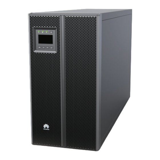
UPS5000-A-30 kVA, 40 kVA and 80 kVA User Manual 2 Overview 2.3 Product Description 2.3.1 Appearance Figure 2-8 UPS5000-A-30 kVA/40 kVA (1) Monitor display (2) Front panel (3) Support base (4) Chassis unit (MDU) Issue 13 (2022-01-19) Copyright © Huawei Technologies Co., Ltd. -
Page 31: Product Structure
UPS5000-A-30 kVA, 40 kVA and 80 kVA User Manual 2 Overview Figure 2-9 UPS5000-A-80 kVA (1) Front panel 1 (2) MDU (3) Front panel 2 (4) Leveling foot (5) Castor (6) Chassis 2.3.2 Product Structure 2.3.2.1 30 kVA/40 kVA UPS... - Page 32 (5) MDU reset button (6) Dual in-line (7) MDU port (8) Cold-start button package (DIP) switch Figure 2-11 UPS5000-A-30 kVA/40 kVA product structure (rear view and enlarged view of certain parts) (1) Ventilation panel (2) Dry contacts (3) Battery (4) Ambient...
- Page 33 UPS5000-A-30 kVA, 40 kVA and 80 kVA User Manual 2 Overview (9) UPS mains input (10) UPS bypass input (11) Battery wiring (12) UPS output terminals (under the terminals (under the terminals (under the terminals (under the cover) cover) cover)
-
Page 34: 80Kva Ups
UPS5000-A-30 kVA, 40 kVA and 80 kVA User Manual 2 Overview DIP1 DIP2 DIP3 LCD Operation Function Remarks Switch Status 3 Hold down the Restores the After restoring the preset Up and Down user name user name and password, buttons at the and password. - Page 35 UPS5000-A-30 kVA, 40 kVA and 80 kVA User Manual 2 Overview Figure 2-12 UPS5000-A-80 kVA product structure (front view) (1) Bypass unit indicators (2) MDU port (3) Bypass unit ready switch (4) MDU reset button (5) DIP switch (6) Power unit indicators...
-
Page 36: Control Port
(7) Slot for dry contact (8) PDU card (optional) NO TE ● UPS5000-A-80 kVA functional components have the same functions as UPS5000-A-30 kVA/40 kVA functional components. For details, see section 2.3.2.1 30 kVA/40 kVA UPS. ● Connect the BMU by using a 04080298 transfer cable, which is delivered with the BMU. - Page 37 UPS5000-A-30 kVA, 40 kVA and 80 kVA User Manual 2 Overview Table 2-2 Functions of the parallel port and BSC port Silk Screen Description PARALLEL The PARALLEL port transmits parallel signals. To connect multiple UPSs in parallel, use parallel cables to connect the parallel ports on the UPSs.
- Page 38 UPS5000-A-30 kVA, 40 kVA and 80 kVA User Manual 2 Overview Silk Screen Description Status BCB_OL Detects the battery circuit Status: breaker (BCB) box. ● Grounded: BCB box connected ● Floated: BCB box not connected The initial status is Grounded.
- Page 39 UPS5000-A-30 kVA, 40 kVA and 80 kVA User Manual 2 Overview Silk Screen Description Status SWITCH STATUS_BP Monitors the bypass input Status: circuit breaker on the ● Open: circuit breaker input PDC. ● Closed: circuit breaker The initial status is Closed.
- Page 40 UPS5000-A-30 kVA, 40 kVA and 80 kVA User Manual 2 Overview Figure 2-14 COM1 pins Table 2-5 COM1 pin definition Description RS485- RS485+ 12V_PORT Figure 2-15 RS485 pins Table 2-6 RS485 pin definition Description RS485_T+ RS485_T- Issue 13 (2022-01-19) Copyright © Huawei Technologies Co., Ltd.
-
Page 41: Typical Configurations
UPS5000-A-30 kVA, 40 kVA and 80 kVA User Manual 2 Overview Description RS485_R+ RS485_R- NO TE If cables are prepared onsite, follow the three methods below: ● Connect pin 1 and pin 2. Pin 1 connects to RS485+ and pin 2 connects to RS485–. -
Page 42: Single Ups
UPS5000-A-30 kVA, 40 kVA and 80 kVA User Manual 2 Overview 2.4.1 Single UPS The UPS5000-A is a high frequency tower-mounted UPS. It uses a unit-level design to handle power functionality, and provides an embedded maintenance bypass switch to ensure maintenance with power on. -
Page 43: Optional Components
UPS5000-A-30 kVA, 40 kVA and 80 kVA User Manual 2 Overview Figure 2-17 Conceptual diagram of a dual-bus system 2.5 Optional Components The UPS5000-A provides a variety of optional components to address various customer requirements. Table 2-8 Optional components Componen... - Page 44 UPS5000-A-30 kVA, 40 kVA and 80 kVA User Manual 2 Overview Componen Model Function Reference Document PDU8000-(0630, 1250, 2000) DCV8-BGA001 Battery bus ● PDU8000-063 Converges the BBB Box User Manual bar (BBB) 0DCV8- energy of BGA001 multiple battery strings. ● PDU8000-125...
- Page 45 UPS5000-A-30 kVA, 40 kVA and 80 kVA User Manual 2 Overview Componen Model Function Reference Document BSC cable 10 m, 15 m Transmits bus synchronizatio n signals in a dual-bus system. NO TE ● Antiseismic kits can be equipped only on the UPS5000-A-80 kVA.
-
Page 46: Installation
UPS5000-A-30 kVA, 40 kVA and 80 kVA User Manual 3 Installation Installation 3.1 Installation Preparations 3.1.1 Site Issue 13 (2022-01-19) Copyright © Huawei Technologies Co., Ltd. - Page 47 UPS5000-A-30 kVA, 40 kVA and 80 kVA User Manual 3 Installation Dimensions Figure 3-1 UPS5000-A-30 kVA/40 kVA installation dimensions (unit: mm) Issue 13 (2022-01-19) Copyright © Huawei Technologies Co., Ltd.
- Page 48 UPS5000-A-30 kVA, 40 kVA and 80 kVA User Manual 3 Installation Figure 3-2 UPS5000-A-80 kVA installation dimensions (unit: mm) Installation Environment ● Do not install the UPS in high temperature, low temperature, and damp areas. For details about environmental specifications.
-
Page 49: Tools And Instruments
Keep a clearance of at least 300 mm at the rear of the cabinet. If you need to perform operations at the rear of the cabinet, keep a clearance of at least 800 Figure 3-3 takes the UPS5000-A-30 kVA/40 kVA as an example to show the installation clearance. Figure 3-3 Installation clearances (unit: mm) 3.1.2 Tools and Instruments... - Page 50 UPS5000-A-30 kVA, 40 kVA and 80 kVA User Manual 3 Installation Tools and Meters Hammer drill and Hand-held Alloy hole saw Heat gun drill bit Φ16 electric drill Diagonal pliers Crimping tools Wire stripper Electric hydraulic pliers Clamp meter Multimeter...
-
Page 51: Power Cables
UPS5000-A-30 kVA, 40 kVA and 80 kVA User Manual 3 Installation Tools and Meters Phillips Insulated torque Heat shrink Insulated screwdriver wrench tubing adjustable wrench (M3/M4/M5/M6/ (M6/M8/M12/ M16) NO TE Table 3-1 lists only the common tools for installation and cable connection. For more dedicated tools required, see the corresponding component manuals. - Page 52 UPS5000-A-30 kVA, 40 kVA and 80 kVA User Manual 3 Installation Item 30 kVA 40 kVA 80 kVA Bypass input Bypass input current (A) Recommended 4 x 10 4 x 16 4 x 35 cross-sectional area Output Output current (A)
- Page 53 UPS5000-A-30 kVA, 40 kVA and 80 kVA User Manual 3 Installation NO TE When the mains input and bypass input share a power source, configure input power cables as mains input power cables. The cables listed in Table 3-2 are used only when the following requirements are met: ●...
- Page 54 UPS5000-A-30 kVA, 40 kVA and 80 kVA User Manual 3 Installation Model Connector Connection Mode Bolt Bolt Hole Torque Specifications Diameter 30 kVA-40 Output Crimped OT 6.5 mm 4.5 N·m connectors terminal 80 kVA Crimped DT 9 mm 13 N·m...
- Page 55 UPS5000-A-30 kVA, 40 kVA and 80 kVA User Manual 3 Installation Figure 3-5 DT terminal for the UPS5000-A Table 3-5 DT terminal specifications for the UPS5000-A Nominal Bolt ΦH d(mm) D(mm) W(mm L(mm) conduct diam (mm) or cross- eter Nomin...
- Page 56 UPS5000-A-30 kVA, 40 kVA and 80 kVA User Manual 3 Installation NO TICE The UPS can generate large leakage currents. A circuit breaker that provides leakage current protection is not recommended. Table 3-7 Recommended input front-end and output back-end circuit breakers...
-
Page 57: Unpacking And Checking
UPS5000-A-30 kVA, 40 kVA and 80 kVA User Manual 3 Installation 3.1.4 Unpacking and Checking NO TICE ● Only trained personnel are allowed to move the UPS. Use a pallet truck to transport the UPS box secured to a wooden support to the installation position. -
Page 58: Kva Ups
UPS5000-A-30 kVA, 40 kVA and 80 kVA User Manual 3 Installation Figure 3-7 Removing packing materials Step 5 Remove the foam and moisture-proof bag, and take out the UPS. Step 6 Check that the UPS is intact. Visually inspect the UPS appearance for shipping damage. If it is damaged, notify the carrier immediately. - Page 59 UPS5000-A-30 kVA, 40 kVA and 80 kVA User Manual 3 Installation Figure 3-8 Removing binding tape Step 4 Remove the packing materials and foam, as shown in Figure 3-9. Figure 3-9 Removing packing materials Step 5 Remove the moisture-proof bag.
- Page 60 UPS5000-A-30 kVA, 40 kVA and 80 kVA User Manual 3 Installation Step 6 Check that the UPS is intact. Visually inspect the UPS appearance for shipping damage. If any damage is founded, notify the carrier immediately. Check that the fittings comply with the packing list. If some fittings are missing or do not comply with the packing list, record the information and contact your local Huawei office immediately.
-
Page 61: Installing A Single Ups
UPS5000-A-30 kVA, 40 kVA and 80 kVA User Manual 3 Installation Step 8 Remove the L-shaped bracket that secures the chassis to the pallet, as shown in Figure 3-11. Figure 3-11 Removing the L-shaped bracket NO TE Store the removed L-shaped bracket, which will be used to secure the UPS. - Page 62 UPS5000-A-30 kVA, 40 kVA and 80 kVA User Manual 3 Installation Figure 3-12 Assembling support bases Step 2 Pull the back-end handle out of the UPS, as shown in Figure 3-13. Figure 3-13 Pulling the back-end handle Loosen the back-end handle screws anticlockwise.
- Page 63 UPS5000-A-30 kVA, 40 kVA and 80 kVA User Manual 3 Installation Figure 3-14 Placing the UPS on support bases (unit: mm) Step 4 Push the back-end handle into the groove, as shown in Figure 3-15. For details, see the instructions on the chassis.
- Page 64 UPS5000-A-30 kVA, 40 kVA and 80 kVA User Manual 3 Installation Figure 3-16 Installing the front panel Insert the bottom half of the panel into the UPS. Push the top half of the panel until it is securely fastened in place.
- Page 65 UPS5000-A-30 kVA, 40 kVA and 80 kVA User Manual 3 Installation Rack-mounting the UPS Step 1 Remove the left and right side panels, handles, and MDU from the UPS chassis, as shown in Figure 3-18. Before you remove the MDU, remove the cables that are connected to the chassis.
- Page 66 UPS5000-A-30 kVA, 40 kVA and 80 kVA User Manual 3 Installation Figure 3-19 Removing the power unit and bypass unit Step 3 Install guide rails (2 U) on the cabinet. Align the lower edge of a guide rail with the lower edge of a U scale, and...
- Page 67 UPS5000-A-30 kVA, 40 kVA and 80 kVA User Manual 3 Installation Figure 3-20 Engaging the mounting brackets (rear view) (1) Scale (2) Mounting bracket (3) Lower edge of a U scale NO TICE Ensure that the lower edge of the guide rail is aligned with the lower edge of a U scale.
- Page 68 UPS5000-A-30 kVA, 40 kVA and 80 kVA User Manual 3 Installation Figure 3-22 Installing floating nuts NO TE Install floating nuts by using a flat-head screwdriver. Secure the back end of the guide rail with panel screws, as shown in Figure 3-23.
- Page 69 UPS5000-A-30 kVA, 40 kVA and 80 kVA User Manual 3 Installation Figure 3-24 The position of the subrack Step 5 Replace the left and right mounting brackets for the power unit, as shown in Figure 3-25. Figure 3-25 Replacing a mounting bracket...
- Page 70 1) clockwise 90 degrees, install it along with the support, and connect cables, as shown in Figure 3-27. Figure 3-27 Installing the MDU Step 8 Install the front panel and rotate the Huawei logo on it clockwise 90 degrees, as shown in Figure 3-28. Issue 13 (2022-01-19)
-
Page 71: Installing The Ups5000-A-80 Kva
UPS5000-A-30 kVA, 40 kVA and 80 kVA User Manual 3 Installation Figure 3-28 Installing the front panel Step 9 (Recommended) Install a lock for the maintenance bypass switch, as shown in Figure 3-17. ----End 3.2.2 Installing the UPS5000-A-80 kVA Installing a UPS by Using Leveling Feet... - Page 72 UPS5000-A-30 kVA, 40 kVA and 80 kVA User Manual 3 Installation Step 2 Check the cabinet levelness using a level. If the cabinet is not leveled, adjust the leveling feet. Step 3 Reinstall the upper and lower front panels. Step 4 (Recommended) Install a lock for the maintenance bypass switch to prevent...
- Page 73 UPS5000-A-30 kVA, 40 kVA and 80 kVA User Manual 3 Installation NO TE Pay attention to the front and back edge lines of the cabinet, preventing incorrect location. Step 2 Use a hammer drill to drill holes for installing the expansion bolts and then install the four expansion bolts in the holes.
- Page 74 UPS5000-A-30 kVA, 40 kVA and 80 kVA User Manual 3 Installation Partially tighten the expansion bolt and vertically insert it into the hole. Knock the expansion bolt using a rubber mallet until the expansion sleeve is fully inserted into the hole.
- Page 75 UPS5000-A-30 kVA, 40 kVA and 80 kVA User Manual 3 Installation Step 1 Install guide rails at the bottom of the rack. The guide rail is 2 U high. The methods for installing guide rails on the left and right sides are the same.
- Page 76 UPS5000-A-30 kVA, 40 kVA and 80 kVA User Manual 3 Installation Figure 3-36 Securing a guide rail (front view) Step 2 Install one reinforced beam on the front and at the rear of the rack, as shown in Figure 3-37. Then tighten the panel screws.
- Page 77 UPS5000-A-30 kVA, 40 kVA and 80 kVA User Manual 3 Installation Figure 3-38 Scale plate Install floating nuts, as shown in Figure 3-22. Figure 3-39 shows the installation positions of floating nuts. Issue 13 (2022-01-19) Copyright © Huawei Technologies Co., Ltd.
- Page 78 UPS5000-A-30 kVA, 40 kVA and 80 kVA User Manual 3 Installation Figure 3-39 Installation positions of floating nuts Step 4 Remove the UPS front panels, MDU (with its support), power units, and bypass unit, as shown in Figure 3-40. Before you move the power unit and bypass unit,...
- Page 79 UPS5000-A-30 kVA, 40 kVA and 80 kVA User Manual 3 Installation Remove UPS front panel 1. Remove UPS front panel 2. Remove the MDU. Remove the power units and bypass unit. Step 5 Install mounting brackets on the chassis, two on the left and two on the right, as...
- Page 80 UPS5000-A-30 kVA, 40 kVA and 80 kVA User Manual 3 Installation Figure 3-42 Placing the chassis into the rack Step 7 Adjust the four leveling feet using an adjustable wrench until the bottom of the chassis is level with the Edge of cabinet line on the scale plate, as shown in Figure 3-43.
- Page 81 UPS5000-A-30 kVA, 40 kVA and 80 kVA User Manual 3 Installation Figure 3-43 Adjusting the leveling feet (1) Bottom of the chassis (2) Edge of cabinet line on the scale plate Step 8 Check the cabinet levelness using a level. If the cabinet is not leveled, adjust the leveling feet.
-
Page 82: Optional) Installing Antiseismic Kits
UPS5000-A-30 kVA, 40 kVA and 80 kVA User Manual 3 Installation Figure 3-44 Securing the chassis to the rack Step 10 Reinstall the power units, bypass unit, MDU (with its support), and UPS font panels. NO TICE After you insert the power unit and bypass unit, rotate the ready switches to... -
Page 83: Optional) Installing A Battery Monitoring Unit
UPS5000-A-30 kVA, 40 kVA and 80 kVA User Manual 3 Installation Figure 3-45 Securing antiseismic kits to the cabinet Step 6 Adjust the cabinet position so that the expansion bolt holes are aligned with the four holes at the bottom of the cabinet. - Page 84 UPS5000-A-30 kVA, 40 kVA and 80 kVA User Manual 3 Installation Figure 3-46 Connecting the UPS and BMU (without ambient temperature and humidity sensor) Issue 13 (2022-01-19) Copyright © Huawei Technologies Co., Ltd.
-
Page 85: Installing Batteries
UPS5000-A-30 kVA, 40 kVA and 80 kVA User Manual 3 Installation Figure 3-47 Connecting the UPS and BMU (with ambient temperature and humidity sensor) 3.2.5 Installing Batteries Context NO TICE ● Before installing batteries, read through the battery safety precautions, obtain the delivered battery installation guide, and install batteries as instructed. -
Page 86: Ups Cable Connection Reference
UPS5000-A-30 kVA, 40 kVA and 80 kVA User Manual 3 Installation NO TICE After you install the BCB box, adjust the end of discharge (EOD) threshold based on backup time, which prevents overcurrent disconnection. The default values are as follows: ●... -
Page 87: Routing Cables
UPS5000-A-30 kVA, 40 kVA and 80 kVA User Manual 3 Installation NO TE Choose an appropriate cabling route based on the actual situation. The figure is for reference only. Step 4 Connect the cable with a crimped terminal to the corresponding copper bar. -
Page 88: Connecting Ground Cables
UPS5000-A-30 kVA, 40 kVA and 80 kVA User Manual 3 Installation Figure 3-50 Removing small covers from the bottom of the cabinet Figure 3-51 shows the power cables routed from the bottom of the cabinet. Figure 3-51 Routing power cables from the bottom of the cabinet... - Page 89 UPS5000-A-30 kVA, 40 kVA and 80 kVA User Manual 3 Installation CA UTION If you do not ground the UPS as required, electromagnetic interference, electric shocks, or fire disasters may occur. NO TICE ● Before cable connections, ensure that all UPS input switches are OFF. Paste warning labels to prevent operation on the switches.
-
Page 90: Connecting Ac Input Power Cables
Step 1 If the mains input and bypass input share a power source, connect AC input power cables to mains input terminals N, and 1L1, 1L2, 1L3 on the UPS. Figure 3-54 Connecting AC input power cables to the UPS5000-A-30 kVA/40 kVA (1) Input N... - Page 91 UPS5000-A-30 kVA, 40 kVA and 80 kVA User Manual 3 Installation Figure 3-55 Connecting AC input power cables to the UPS5000-A-80 kVA (1) Input N (2) Input 1L1 (3) Input 1L2 (4) Input 1L3 NO TE ● Mains and bypass input of the delivered UPSs by default share one power source. The neutral terminals of the mains and the bypass are interconnected internally.
- Page 92 UPS5000-A-30 kVA, 40 kVA and 80 kVA User Manual 3 Installation Figure 3-56 Removing copper bars from the UPS5000-A-30 kVA/40 kVA NO TE Install the copper bars from within outwards based on the ascending order of their numbers. Figure 3-57 Removing copper bars from the UPS5000-A-80 kVA Step 2 Connect mains input cables to mains input terminals N, and 1L1, 1L2, 1L3 on the UPS cabinet.
- Page 93 UPS5000-A-30 kVA, 40 kVA and 80 kVA User Manual 3 Installation Figure 3-58 Connecting AC input power cables to the UPS5000-A-30 kVA/40 kVA (1) Bypass input N (2) Bypass input 2L1 (3) Bypass input 2L2 (4) Bypass input 2L3 (5) Mains input N...
-
Page 94: Connecting Ac Output Power Cables
Connect AC output power cables to output terminals N, U, V, and W on the UPS cabinet, as shown in Figure 3-60 Figure 3-61. Figure 3-60 Connecting AC output power cables to the UPS5000-A-30 kVA/40 kVA (1) Output N (2) Output U (3) Output V (4) Output W Issue 13 (2022-01-19) Copyright ©... -
Page 95: Connecting Battery Cables
UPS5000-A-30 kVA, 40 kVA and 80 kVA User Manual 3 Installation Figure 3-61 Connecting AC output power cables to the UPS5000-A-80 kVA (1) Output N (2) Output U (3) Output V (4) Output W 3.2.7.5 Connecting Battery Cables D ANGER The battery voltage may result in serious injury. - Page 96 UPS5000-A-30 kVA, 40 kVA and 80 kVA User Manual 3 Installation Figure 3-62 Connecting battery cables to the UPS5000-A-30 kVA/40 kVA (1) Battery input + (2) Battery input N (3) Battery input – Figure 3-63 Connecting battery cables to the UPS5000-A-80 kVA...
-
Page 97: Remote Epo
Figure 3-64 Neutral wire 3.2.8 Remote EPO NO TICE ● Huawei does not provide the EPO switch or cable. Prepare them by yourself. The recommended cable is 22 AWG. ● Equip the EPO switch with a protective cover to prevent misoperations, and cover the cable with protective tubing. -
Page 98: Connecting Communications Cables
UPS5000-A-30 kVA, 40 kVA and 80 kVA User Manual 3 Installation 3.2.9 Connecting Communications Cables Procedure Step 1 Connect the external network management device to the RS485 port of the monitoring interface card. Step 2 Connect the network port on a PC to the FE port of the monitoring interface card. - Page 99 UPS5000-A-30 kVA, 40 kVA and 80 kVA User Manual 3 Installation Figure 3-67 Cable connections for a UPS5000-A-30 kVA/40 kVA 1+1 parallel system (1) Mains input power (2) Bypass input power (3) Battery cable (4) Output power cable cable cable...
- Page 100 UPS5000-A-30 kVA, 40 kVA and 80 kVA User Manual 3 Installation NO TICE The specifications of power cables on each UPS should be the same to achieve current equalization in bypass mode. The power cables include bypass input power cables and UPS output power cables.
- Page 101 UPS5000-A-30 kVA, 40 kVA and 80 kVA User Manual 3 Installation Figure 3-70 Cable connections for a UPS5000-A-30 kVA/40 kVA dual-bus system (1) Mains input power (2) Bypass input power (3) Battery cable (4) Output power cable cable cable Issue 13 (2022-01-19)
-
Page 102: Connecting Signal Cables
UPS5000-A-30 kVA, 40 kVA and 80 kVA User Manual 3 Installation Figure 3-71 Cable connections for a UPS5000-A-80 kVA dual-bus system (1) Mains input power (2) Bypass input power (3) Battery cable (4) Output power cable cable cable ----End 3.3.2 Connecting Signal Cables... - Page 103 Figure 3-72 Connecting signal cables in an N+X parallel system Figure 3-73 shows how to connect signal cables to four UPSs in parallel. Figure 3-73 Connecting signal cables in a UPS5000-A-30 kVA/40 kVA N+X parallel system ● Dual-bus system, Connect cables to BSC ports on the master and slave UPS systems.
-
Page 104: Installation Verification
UPS5000-A-30 kVA, 40 kVA and 80 kVA User Manual 3 Installation Figure 3-74 Connecting signal cables in a UPS5000-A-30 kVA/40 kVA dual- bus system Connecting Other Signal Cables Connect the signal cables for each single UPS in a parallel system. - Page 105 UPS5000-A-30 kVA, 40 kVA and 80 kVA User Manual 3 Installation Item Acceptance Criteria Marks for tightened screws Tightened screws are marked. Serial port connection Signal cables are connected properly and (security protection securely. mechanism supported) Marks for tightened screws Both ends of a cable are labeled.
- Page 106 UPS5000-A-30 kVA, 40 kVA and 80 kVA User Manual 3 Installation Item Acceptance Criteria Operating environment The inside and outside of the cabinet, and other operating components, are free from conductive dust. ● 30 kVA/40 kVA UPS – Ensure that there is no foreign...
- Page 107 UPS5000-A-30 kVA, 40 kVA and 80 kVA User Manual 3 Installation Figure 3-75 30 kVA/40 kVA UPS (1) Wiring terminals (2) Wiring terminal box Figure 3-76 80 kVA UPS (1) Wiring terminals (2) UPS bottom Issue 13 (2022-01-19) Copyright © Huawei Technologies Co., Ltd.
- Page 108 UPS5000-A-30 kVA, 40 kVA and 80 kVA User Manual 3 Installation Figure 3-77 Fill the holes with sealing putty (1) Paper protective film (2) Sealing putty Issue 13 (2022-01-19) Copyright © Huawei Technologies Co., Ltd.
-
Page 109: Lcd And Webui
UPS5000-A-30 kVA, 40 kVA and 80 kVA User Manual 4 LCD and WebUI LCD and WebUI 4.1 MDU The MDU is located on the front panel of the UPS. The MDU allows you to control the UPS operation, set parameters, and view running status and alarms. - Page 110 UPS5000-A-30 kVA, 40 kVA and 80 kVA User Manual 4 LCD and WebUI Indicators Table 4-1 Indicator description Indicator Color Status Meaning Mains indicator Green The UPS is in normal mode. The UPS is not in normal mode. Battery indicator Yellow The UPS is in battery mode.
-
Page 111: Lcd
UPS5000-A-30 kVA, 40 kVA and 80 kVA User Manual 4 LCD and WebUI Button Meaning Description ▲ Press ▲ or ▼ to scroll upward or downward. Set parameters by using the list or step ▼ Down increase or decrease. Startup/Enter/Mute On the default screen, hold down more than 5s. -
Page 112: Overview
UPS5000-A-30 kVA, 40 kVA and 80 kVA User Manual 4 LCD and WebUI 4.2.1 Overview Symbol Meaning Table 4-3 Symbol conventions Symbol Meaning Press A. Press A and then B. NO TE The symbol conventions apply to all chapters in this document. - Page 113 UPS5000-A-30 kVA, 40 kVA and 80 kVA User Manual 4 LCD and WebUI Table 4-4 Mains Input Item Description Van, Vbn, and Vcn Mains input phase voltages Ia, Ib, and Ic Mains input phase currents Frequency Mains input frequency Vab, Vbc, and Vca...
- Page 114 UPS5000-A-30 kVA, 40 kVA and 80 kVA User Manual 4 LCD and WebUI Table 4-7 UPS Output Item Description Van, Vbn, and Vcn UPS output phase voltage Ia, Ib, and Ic UPS output phase current Power factor_A, Power Proportion of passive power to apparent power for...
-
Page 115: Alarms
UPS5000-A-30 kVA, 40 kVA and 80 kVA User Manual 4 LCD and WebUI Table 4-10 Environment Monitoring Item Description Ambient temp. Temperature measured by the ambient temperature and humidity sensor. An ambient temperature and humidity sensor is required. If there is no such sensor, the data uploaded by the bypass unit is displayed. - Page 116 UPS5000-A-30 kVA, 40 kVA and 80 kVA User Manual 4 LCD and WebUI Figure 4-5 Sort Alarms screen ● Generate (latest first) Active alarms are displayed by occurrence time. The latest alarms are listed first. ● Severity (highest first) Active alarms are displayed by severity. The most critical alarms are listed first.
-
Page 117: Settings Screen
UPS5000-A-30 kVA, 40 kVA and 80 kVA User Manual 4 LCD and WebUI 4.2.4 Settings Screen On the Main Menu screen, select Settings, and press . On the login screen displayed, enter the password (preset password: 000001), and press . The Settings screen is displayed. - Page 118 UPS5000-A-30 kVA, 40 kVA and 80 kVA User Manual 4 LCD and WebUI Communication Settings Figure 4-8 Comm Settings screen Figure 4-9 IP settings IP address allocation ● Manual: After the MDU connects to the PC over a network cable, check that their IP addresses are two different values on the same network segment.
- Page 119 UPS5000-A-30 kVA, 40 kVA and 80 kVA User Manual 4 LCD and WebUI Figure 4-10 RS485 communication settings Item Description Default Value Value Range Comm. This serial port address is 1–254 address allocated by the user. Baud rate Select a baud rate to match...
- Page 120 UPS5000-A-30 kVA, 40 kVA and 80 kVA User Manual 4 LCD and WebUI Item Description Default Value Value Range Quantity Number of cascaded ambient 0–4 temperature and humidity sensors Figure 4-12 Battery temperature sensor Item Description Default Value Value Range Start address 16–28...
- Page 121 UPS5000-A-30 kVA, 40 kVA and 80 kVA User Manual 4 LCD and WebUI System Settings NO TICE ● Single/Parallel, Outp volt lev., and Outp. freq. must be set according to the system configuration. Otherwise, alarms may be generated or serious faults may occur.
- Page 122 UPS5000-A-30 kVA, 40 kVA and 80 kVA User Manual 4 LCD and WebUI Item Description Default Value Value Range BSC mode ● Set this parameter to Non-BSC Non-BSC, Standard BSC mode for Standard BSC a dual-bus system. ● After setting this...
- Page 123 UPS5000-A-30 kVA, 40 kVA and 80 kVA User Manual 4 LCD and WebUI Figure 4-15 Input Settings screen Item Description Default Value Value Range Inp. Input adaptability mode 1: It Mode 2 Mode 1, Mode adaptabil. is applicable to the normal...
- Page 124 UPS5000-A-30 kVA, 40 kVA and 80 kVA User Manual 4 LCD and WebUI Item Description Default Value Value Range Outp. freq. Specifies the system output 50 Hz 50 Hz, 60 Hz frequency level. Output The specific voltage range The default 380 V: 209.0–...
- Page 125 UPS5000-A-30 kVA, 40 kVA and 80 kVA User Manual 4 LCD and WebUI Item Description Default Value Value Range Max. voltage When the difference between ● When the voltage level is the bypass voltage and the 380 V, the value range is...
- Page 126 UPS5000-A-30 kVA, 40 kVA and 80 kVA User Manual 4 LCD and WebUI Figure 4-18 Battery Settings Screen ● Basic Parameters Figure 4-19 Basic Parameters screen Item Description Default Value Range Value Single batt. Specifies the voltage of 12 V 2, 6, 12 volt.
- Page 127 UPS5000-A-30 kVA, 40 kVA and 80 kVA User Manual 4 LCD and WebUI Item Description Default Value Range Value Maint. Specifies the interval for 0–365 period reminding users of battery maintenance. Cur. limit The charging current limit 0.1C10 0.05C10 to...
- Page 128 UPS5000-A-30 kVA, 40 kVA and 80 kVA User Manual 4 LCD and WebUI Item Description Default Value Range Value Cell float Indicates the battery float 2.25 V/cell 2.23 V/cell– volt. charging voltage. The 2.30 V/cell parameter is configurable in any mode.
- Page 129 UPS5000-A-30 kVA, 40 kVA and 80 kVA User Manual 4 LCD and WebUI Figure 4-23 Shallow Discharge Test screen Item Description Default Value Range Value Scheduled When certain conditions Disabled Disabled, test are met, the charger shuts Enabled down, the UPS transfers...
- Page 130 UPS5000-A-30 kVA, 40 kVA and 80 kVA User Manual 4 LCD and WebUI – Warning thresh. parameter If the warning function is enabled, a warning is generated when the backup time reaches the specified value. ● Remaining cap. Figure 4-25 Remaining cap. screen –...
-
Page 131: Control
UPS5000-A-30 kVA, 40 kVA and 80 kVA User Manual 4 LCD and WebUI Item Description Enable or disable PDC maintenance circuit breaker status detection. BP/SYSMT If the BP/SYSMT switch is set to Enable, the port has dry contact signal access. Using the port depends on the status of the BP/SYSMT switch. - Page 132 UPS5000-A-30 kVA, 40 kVA and 80 kVA User Manual 4 LCD and WebUI Shutting Down the Inverter You can shut down the inverter manually by pressing Shutdown. Maintaining Batteries Figure 4-28 Maintain Batteries screen Item Description Update Installation Date You can update the battery installation time to the current system time.
-
Page 133: About Screen
UPS5000-A-30 kVA, 40 kVA and 80 kVA User Manual 4 LCD and WebUI 4.2.6 About Screen Figure 4-29 shows the About screen. Figure 4-29 About screen On the About screen, you can view the model, manufacturer, monitoring version, and power version. -
Page 134: Monitoring Page
UPS5000-A-30 kVA, 40 kVA and 80 kVA User Manual 4 LCD and WebUI Table 4-12 User description Default User Preset User Rights Password admin (system Changeme Performs all operations on the LCD and WebUI, administrator) including system running information browsing, system information exporting,... -
Page 135: Parameter Settings
UPS5000-A-30 kVA, 40 kVA and 80 kVA User Manual 4 LCD and WebUI Figure 4-30 Monitoring page NO TE If NA is displayed for load ratio, the value is invalid or outside the range. Table 4-13 Monitoring page details Number... - Page 136 UPS5000-A-30 kVA, 40 kVA and 80 kVA User Manual 4 LCD and WebUI System Settings Item Description Default Value Value Range High ambient An alarm is generated when 40–60 temperature the ambient temperature alarm reaches or exceeds the threshold (°C) threshold specified by this parameter.
- Page 137 UPS5000-A-30 kVA, 40 kVA and 80 kVA User Manual 4 LCD and WebUI Item Description Default Value Value Range Collect real- If this parameter is set to Disable Disable, time site Enable, one waveform can Enable waveform be stored manually.
- Page 138 UPS5000-A-30 kVA, 40 kVA and 80 kVA User Manual 4 LCD and WebUI Item Description Default Value Value Range Output The interruption for the UPS 0 ms, 40 ms, interruption to transfer from normal 60 ms, 80 ms, transfer time mode to bypass mode is 1–2...
- Page 139 UPS5000-A-30 kVA, 40 kVA and 80 kVA User Manual 4 LCD and WebUI Item Description Default Value Value Range Specifies whether to Enable Disable, overvoltage automatically clear the alarm Enable recovery and restart the rack when the rectifier or inverter shuts down due to a bus overvoltage alarm.
- Page 140 UPS5000-A-30 kVA, 40 kVA and 80 kVA User Manual 4 LCD and WebUI Bypass Setting Item Description Default Value Value Range BPM mode Specifies whether to start Enable Disable, upon BPM bypass mode when Enable overtemp. overtemperature occurs. Lightload Enable or disable the light...
- Page 141 UPS5000-A-30 kVA, 40 kVA and 80 kVA User Manual 4 LCD and WebUI Item Description Default Value Value Range Float volt. If this parameter is set to Enable, the Enable Disable, temp. float voltage is calibrated based on the Enable comp.
- Page 142 UPS5000-A-30 kVA, 40 kVA and 80 kVA User Manual 4 LCD and WebUI Item Description Default Value Value Range Forced When batteries are continuously under 12–24 equalized float charging or hibernation, enable charging forced equalized charging. When the protection forced equalized charging time reaches...
-
Page 143: Communications Settings
UPS5000-A-30 kVA, 40 kVA and 80 kVA User Manual 4 LCD and WebUI Item Description Default Value Value Range The calculation formula is (Charge/ Single batt. 10–30 Discharge voltage – Average voltage)/ dis. voltage Average voltage x 100%. deviation alarm thres. -
Page 144: Query Page
UPS5000-A-30 kVA, 40 kVA and 80 kVA User Manual 4 LCD and WebUI Figure 4-33 Control page 4.3.3 Query Page 4.3.3.1 Historical Alarms Page On the homepage, click the Query tab to open the Historical Alarms page for querying historical alarms based on severity, generation time, and clear time. -
Page 145: Config. Page
UPS5000-A-30 kVA, 40 kVA and 80 kVA User Manual 4 LCD and WebUI 4.3.4 Config. Page 4.3.4.1 User Management On the home page, choose Config. > User Mgmt. Figure 4-36 User management NO TE ● On the User Mgmt. page, you can add, modify, delete, lock, or unlock users and change user passwords. - Page 146 UPS5000-A-30 kVA, 40 kVA and 80 kVA User Manual 4 LCD and WebUI Figure 4-37 Site configuration ● The NTP parameters are used to set the NTP server address, port number, and synchronization interval. ● The default SNMP version is SNMPv3, and the preset MD5/SHA password is Changeme1, and the preset DES/AES password is Changeme2.
-
Page 147: Rccmd
UPS5000-A-30 kVA, 40 kVA and 80 kVA User Manual 4 LCD and WebUI is used to configure a server for receiving alarm emails from the monitoring system. ● Set Email and Alarm Severity and simulate an alarm. Check that the alarm email can be received. - Page 148 UPS5000-A-30 kVA, 40 kVA and 80 kVA User Manual 4 LCD and WebUI Figure 4-39 RCCMD function enabled SSL Encrypted Transmission NO TICE The SSL encrypted transmission set on the page of the UPS5000 monitor display module (MDU) must be the same as the setting on the RCCMD client.
- Page 149 UPS5000-A-30 kVA, 40 kVA and 80 kVA User Manual 4 LCD and WebUI Figure 4-40 SSL encrypted transmission enabled by default Figure 4-41 SSL encrypted transmission disabled Event Configuration The MDU supports 17 alarm events, and a maximum of 50 jobs can be added for...
- Page 150 UPS5000-A-30 kVA, 40 kVA and 80 kVA User Manual 4 LCD and WebUI NO TE Number of jobs = Number of RCCMD Shutdown jobs + Number of RCCMD Message jobs + Number of RCCMD Execute jobs + Number of RCCMD TRAP jobs.
- Page 151 UPS5000-A-30 kVA, 40 kVA and 80 kVA User Manual 4 LCD and WebUI Table 4-15 Buttons after one event is expanded Name Description Button for modifying A dialog box for modifying a job is displayed after you click this button.
- Page 152 UPS5000-A-30 kVA, 40 kVA and 80 kVA User Manual 4 LCD and WebUI Figure 4-45 RCCMD message ● RCCMD Execute: Specify the RCCMD client IP address, port, and command to be executed. For example, enter SHUTDOWN, and the RCCMD client will shut down the computer after receiving the command.
- Page 153 UPS5000-A-30 kVA, 40 kVA and 80 kVA User Manual 4 LCD and WebUI Figure 4-47 RCCMD TRAP Table 4-16 RCCMD TRAP signal Signal Name Description Unit in the UPS #MODEL Device name #OUTPOWER Active power #OUTVOLT Output voltage #OUTCURR Output current...
- Page 154 UPS5000-A-30 kVA, 40 kVA and 80 kVA User Manual 4 LCD and WebUI Signal Name Description Unit in the UPS #CNT_PF Power supply failure times #CNT_BL Low battery voltage times #INPHASES Input phases #OUTPHASES Output phases When you add a job, five sending methods are available. The latter three methods can take effect only when the event condition is still true after the specified seconds.
-
Page 155: Managing The Ups By Using The Nms Complying With Rfc1628 Standard
UPS5000-A-30 kVA, 40 kVA and 80 kVA User Manual 4 LCD and WebUI Figure 4-48 RCCMD certificate management NO TE If the RCCMD certificate key has been encrypted, enable and enter the key password. 4.3.4.4 Managing the UPS by Using the NMS Complying with RFC1628... -
Page 156: Protecting The Server By Using The Rccmd Software
UPS5000-A-30 kVA, 40 kVA and 80 kVA User Manual 4 LCD and WebUI Managing the UPS by Using the NMS ● Applying for Access Rights To manage the UPS by using the UNMS II of Generex over the MDU, apply to the system administrator of the MDU for access rights and add the NMS information to the NMS access list of the MDU. -
Page 157: Rccmd Event Shutdown And Message Sending
UPS5000-A-30 kVA, 40 kVA and 80 kVA User Manual 4 LCD and WebUI 4.3.5.2 RCCMD Event Shutdown and Message Sending Procedure Step 1 On the RCCMD client, choose Connections, add the server IP address, and set the encryption mode to encryption. -
Page 158: Ups Alive Check Function
UPS5000-A-30 kVA, 40 kVA and 80 kVA User Manual 4 LCD and WebUI Step 6 On the RCCMD client, you can view messages through the View Event Log at the upper left corner. ----End 4.3.5.3 UPS Alive Check Function Context... - Page 159 UPS5000-A-30 kVA, 40 kVA and 80 kVA User Manual 4 LCD and WebUI Figure 4-52 Heartbeat detecting mode on the RCCMD client You can also manually detect heartbeat by clicking Run alive check now..Figure 4-53 Detecting heartbeat manually Issue 13 (2022-01-19)
- Page 160 UPS5000-A-30 kVA, 40 kVA and 80 kVA User Manual 4 LCD and WebUI Figure 4-54 Detecting heartbeat manually and successfully ----End Issue 13 (2022-01-19) Copyright © Huawei Technologies Co., Ltd.
-
Page 161: Operations
Procedure Step 1 Close the upstream bypass and mains input switches. After the UPS is powered on, initialization begins. The MDU displays the Huawei logo and an initialization progress bar. Step 2 After the LCD starts properly, perform the following operations: ●... - Page 162 UPS (when no battery string is shared). High or low charging power shortens the battery lifespan, or even promptly damages batteries. To determine the battery capacity, contact Huawei technical support. Figure 5-1 Settings wizard Step 3 After the quick settings, if no alarm is displayed on the LCD, go to the next step. If any abnormal alarm is displayed, clear the abnormal alarm.
- Page 163 UPS5000-A-30 kVA, 40 kVA and 80 kVA User Manual 5 Operations Step 4 View the system running diagram on the LCD to check whether the parallel system has transferred to bypass mode. Step 5 Start the inverter. ● Start the inverter on the LCD.
- Page 164 UPS5000-A-30 kVA, 40 kVA and 80 kVA User Manual 5 Operations Figure 5-3 WebUI login On the home page, choose Monitoring > Control. Click Inv. ON. In the displayed dialog box, click OK to start the inverter. Figure 5-4 Starting the inverter...
-
Page 165: Shutting Down And Powering Off The Ups
UPS5000-A-30 kVA, 40 kVA and 80 kVA User Manual 5 Operations Ph. B output volt., and Ph. C output volt. under Actual Value and click Submit at the end of each row to commission the voltages. NO TE Commission the voltages on other power uints one by one. -
Page 166: Starting The Ups In Battery Mode
UPS5000-A-30 kVA, 40 kVA and 80 kVA User Manual 5 Operations ● Shut down the inverter on the WebUI. On the homepage, choose Monitoring > Control. Click Inv. OFF. In the displayed dialog box, click OK to shut down the inverter, as shown in Figure 5-7. -
Page 167: Transferring To Bypass Mode
Step 4 Press and hold down the BATT START button on the bypass unit for at least 2 seconds. The system automatically enters the battery cold start status. The LCD displays the Huawei logo and an initialization progress bar. Step 5 After LCD initialization, start the inverter on the LCD. -
Page 168: Testing Batteries
UPS5000-A-30 kVA, 40 kVA and 80 kVA User Manual 5 Operations Step 2 Select a value (±5%, ±6%, ±7%, ±8%, ±9%, or ±10%) from the ECO volt. range drop-down list box, as shown in Figure 5-8. Click to select ECO volt. range, press ▲... -
Page 169: Shallow Discharge Test
UPS5000-A-30 kVA, 40 kVA and 80 kVA User Manual 5 Operations Procedure Step 1 Log in to the WebUI. Step 2 On the Monitoring > Control > System Commands and Tests page, click Start next to Forced equalized charging to start a forced equalized charging test. - Page 170 UPS5000-A-30 kVA, 40 kVA and 80 kVA User Manual 5 Operations Step 2 On the home screen of the WEBUI, choose Monitoring > Param. Settings > Battery Setting, and set Sched. shallow dis. test to Enable. Step 3 Set Sched. shallow dis. test time, Sched. shallow dis. test interval and Shallow dis.
-
Page 171: Capacity Test
UPS5000-A-30 kVA, 40 kVA and 80 kVA User Manual 5 Operations 5.6.3 Capacity Test Context NO TICE Before conducting a capacity test, check whether the requirements of a capacity test are met. If the requirements are met, the button for starting a capacity test is available. -
Page 172: Test Data Download
UPS5000-A-30 kVA, 40 kVA and 80 kVA User Manual 5 Operations NO TE Click Stop next to Capacity test in any of the following cases: ● The battery discharge voltage reaches the end of discharge (EOD) voltage plus 0.01 V. - Page 173 Rotate the maintenance bypass switch to ON. The system hence transfers to maintenance bypass mode, as shown in Figure 5-14 Figure 5-15. Figure 5-14 Turning on the maintenance bypass switch on the UPS5000-A-30 kVA/40 kVA Issue 13 (2022-01-19) Copyright © Huawei Technologies Co., Ltd.
-
Page 174: Transferring From Maintenance Bypass Mode To Normal Mode
UPS5000-A-30 kVA, 40 kVA and 80 kVA User Manual 5 Operations Figure 5-15 Turning on the maintenance bypass switch on the UPS5000-A-80 kVA The UPS transfers to maintenance bypass mode. The Maint. Breaker closed alarm is displayed on the LCD and WebUI, as shown in... - Page 175 5-19. The Maint. breaker closed alarm disappears on the LCD and WebUI. View the system running diagram on the LCD or WebUI to check that the UPS has transferred to bypass mode. Figure 5-18 Turning off the maintenance bypass switch on the UPS5000-A-30 kVA/40 kVA Issue 13 (2022-01-19)
-
Page 176: Performing Epo
UPS5000-A-30 kVA, 40 kVA and 80 kVA User Manual 5 Operations Figure 5-19 Turning off the maintenance bypass switch on the UPS5000-A-80 kVA Step 2 Start the inverter. ----End 5.9 Performing EPO Context NO TICE ● On the WebUI, EPO can be performed only when Monitoring > Param. -
Page 177: Clearing The Epo State
UPS5000-A-30 kVA, 40 kVA and 80 kVA User Manual 5 Operations Figure 5-20 EPO alarm on the LCD Figure 5-21 EPO alarm on the WebUI ----End 5.10 Clearing the EPO State Procedure Step 1 Turn off the external EPO switch that connects to the dry contact. Ensure that the EPO switch is not in the EPO state. - Page 178 UPS5000-A-30 kVA, 40 kVA and 80 kVA User Manual 5 Operations ● WebUI On the WebUI, choose Monitoring > Control and click Clear Fault to clear the EPO alarm, as shown in Figure 5-24. Figure 5-24 Clearing the alarm on the WebUI Step 3 Check that the EPO alarm has disappeared from the alarm list.
-
Page 179: Routine Maintenance
Customers are not allowed to maintain components behind protective covers that can be removed only using tools. If the components are to be maintained, contact Huawei technical support. ● Only maintenance engineers can maintain power units and bypass units. -
Page 180: Monthly Maintenance
UPS5000-A-30 kVA, 40 kVA and 80 kVA User Manual 6 Routine Maintenance 6.1.1 Monthly Maintenance Table 6-1 Monthly maintenance Check Item Expected Result Troubleshooting Operating ● Ambient temperature: 0– ● If the humidity or environment 40°C temperature is abnormal, check the air conditioner ●... -
Page 181: Annual Maintenance
UPS5000-A-30 kVA, 40 kVA and 80 kVA User Manual 6 Routine Maintenance Check Item Expected Result Troubleshooting Parameter The configuration of the Reset the parameters. configuration output voltage grade, frequency, number of batteries, and battery capacity meets requirements. Status record... -
Page 182: Battery Maintenance
UPS5000-A-30 kVA, 40 kVA and 80 kVA User Manual 6 Routine Maintenance Table 6-4 Service life parameters for replaceable components and recommended replacement intervals Key Component Design Service Life Recommended Replacement Interval Power unit 15 years 10 years Bypass unit... -
Page 183: Monthly Maintenance
UPS5000-A-30 kVA, 40 kVA and 80 kVA User Manual 6 Routine Maintenance 6.2.2 Monthly Maintenance Table 6-5 Monthly maintenance Item Expected Result Troubleshooting Battery No battery management Identify the cause of an alarm management alarm is generated. based on the alarm alarm information. -
Page 184: Quarterly Maintenance
UPS5000-A-30 kVA, 40 kVA and 80 kVA User Manual 6 Routine Maintenance 6.2.3 Quarterly Maintenance Table 6-6 Quarterly maintenance Item Expected Result Troubleshooting Battery temperature The difference between 1. Install the temperature sensor measurement the temperature sensor in the correct... -
Page 185: Annual Maintenance
UPS5000-A-30 kVA, 40 kVA and 80 kVA User Manual 6 Routine Maintenance Item Expected Result Troubleshooting Shallow discharge test Conduct a shallow 1. If the batteries cannot (recommended) discharge test when the discharge normally, UPS is backed up to verify... -
Page 186: Troubleshooting
EOD voltage and 11.3 V/cell. For details about how to rectify common faults, see Table 7-1. If any unmentioned faults occur, see the alarm list chapter, or contact Huawei technical support. Issue 13 (2022-01-19) Copyright © Huawei Technologies Co., Ltd. - Page 187 UPS5000-A-30 kVA, 40 kVA and 80 kVA User Manual 7 Troubleshooting Table 7-1 Solutions to common faults Case Symptom Possible Cause Measure The rectifier is not The mains voltage exceeds Check whether the mains rectifier working, and the bus the upper threshold 280 V...
- Page 188 UPS5000-A-30 kVA, 40 kVA and 80 kVA User Manual 7 Troubleshooting NO TE For details about component replacement and maintenance involved in Troubleshooting and Alarm List, consult Huawei maintenance engineers. Issue 13 (2022-01-19) Copyright © Huawei Technologies Co., Ltd.
-
Page 189: Technical Specifications
UPS5000-A-30 kVA, 40 kVA and 80 kVA User Manual 8 Technical Specifications Technical Specifications 8.1 Physical Specifications Item 30 kVA 40 kVA 80 kVA Cabling mode Cables are routed from the bottom. Protection level IP20 Communication Optional card slot, RS485 port, and FE port; SNMP and... -
Page 190: Safety Regulations And Emc
UPS5000-A-30 kVA, 40 kVA and 80 kVA User Manual 8 Technical Specifications Item 30 kVA 40 kVA 80 kVA Storage temperature –40°C to +70°C Humidity 0–95% RH (non-condensing) Altitude 0–1000 m When the altitude is above 1000 m (maximum 4000 m), see IEC62040-3 to check how the load power is derated. -
Page 191: Bypass Input Electrical Specifications
UPS5000-A-30 kVA, 40 kVA and 80 kVA User Manual 8 Technical Specifications Item 30 kVA 40 kVA 80 kVA Input voltage 80–280 V AC (phase voltage) ● At 30–40°C: The UPS works at full load when the voltage is 187–280 V AC and is derated to 40% load when the voltage is 187–80 V AC. -
Page 192: Output Electrical Specifications
UPS5000-A-30 kVA, 40 kVA and 80 kVA User Manual 8 Technical Specifications Item 30 kVA 40 kVA 80 kVA Battery string No battery string is shared by default. Battery string sharing sharing is supported in a parallel system. Charge voltage ●... -
Page 193: System Electrical Specifications
UPS5000-A-30 kVA, 40 kVA and 80 kVA User Manual 8 Technical Specifications 8.9 System Electrical Specifications Item 30 kVA 40 kVA 80 kVA Parallel system Parallel signals use redundancy design. reliability Parallel system Supported Issue 13 (2022-01-19) Copyright © Huawei Technologies Co., Ltd. -
Page 194: A Menu Hierarchy
UPS5000-A-30 kVA, 40 kVA and 80 kVA User Manual A Menu Hierarchy Menu Hierarchy A.1 LCD Menus Level-1 Menu Level-2 Menu Level-3 Menu Main Menu Status Mains Input Bypass Input Battery Status UPS Output Local-UPS Load Parallel-System Load Environment Monitoring... -
Page 195: Menus On The Webui
UPS5000-A-30 kVA, 40 kVA and 80 kVA User Manual A Menu Hierarchy Level-1 Menu Level-2 Menu Level-3 Menu Bypass Settings Battery Settings Dry Contact Set Settings Wizard Restore Default Settings Control Inv. ON Inv. OFF Parallel Inv. ON (available in parallel UPS mode) Parallel Inv. - Page 196 UPS5000-A-30 kVA, 40 kVA and 80 kVA User Manual A Menu Hierarchy Level-1 Menu Level-2 Menu Level-3 Menu Battery Settings Dry Contacts Comm. Config. IP Settings RS485 Settings ModbusTCP Settings Amb T/H Sensor Batt Temp Sensor WiFi Settings Control System Commands and...
- Page 197 UPS5000-A-30 kVA, 40 kVA and 80 kVA User Manual A Menu Hierarchy Level-1 Menu Level-2 Menu Level-3 Menu ModbusTCP CA Certificate Management ModbusTCP Authentication eUPS Certificate Management RCCMD RCCMD SSL Encrypted Transmission Event Configuration RCCMD Certificate Management Maint. Calib Module Commissioning Var.
-
Page 198: B Alarm List
UPS5000-A-30 kVA, 40 kVA and 80 kVA User Manual B Alarm List Alarm List Alarm ID Alarm Severity Cause Solution (Alarm Name ID-Cause 0001-1 Mains Minor ● Cable 1. Check whether cables to mains are voltage connections disconnected, loose, or incorrectly abnormal connected. - Page 199 UPS5000-A-30 kVA, 40 kVA and 80 kVA User Manual B Alarm List Alarm ID Alarm Severity Cause Solution (Alarm Name ID-Cause 0005-1 Mains Minor Cable 1. Secure or connect the neutral wire to neutral connections the cabinet if it is loose or absent are incorrect.
- Page 200 UPS5000-A-30 kVA, 40 kVA and 80 kVA User Manual B Alarm List Alarm ID Alarm Severity Cause Solution (Alarm Name ID-Cause 0020-1 Battery Critical Batteries are 1. Check whether battery polarities are connected not properly correctly installed by using a reversely installed.
- Page 201 UPS5000-A-30 kVA, 40 kVA and 80 kVA User Manual B Alarm List Alarm ID Alarm Severity Cause Solution (Alarm Name ID-Cause 0026-1 Low battery Minor ● Battery 1. If the low battery voltage alarm is voltage discharge generated in battery mode, check results in whether the mains voltage recovers.
- Page 202 UPS5000-A-30 kVA, 40 kVA and 80 kVA User Manual B Alarm List Alarm ID Alarm Severity Cause Solution (Alarm Name ID-Cause 0032-1 Battery Critical ● The battery 1. Check the battery voltage. overvoltage voltage is 2. Check that the configured number of...
- Page 203 UPS5000-A-30 kVA, 40 kVA and 80 kVA User Manual B Alarm List Alarm ID Alarm Severity Cause Solution (Alarm Name ID-Cause 0043-1 Critical ● The fan for Replace the faulty power unit. abnormal the power unit is abnormal. ● The fan...
- Page 204 UPS5000-A-30 kVA, 40 kVA and 80 kVA User Manual B Alarm List Alarm ID Alarm Severity Cause Solution (Alarm Name ID-Cause 0564-1 Overload Critical ● The load is 1. Check that there is no overload. timeout excessive. 2. Check that the unit power is not ●...
- Page 205 UPS5000-A-30 kVA, 40 kVA and 80 kVA User Manual B Alarm List Alarm ID Alarm Severity Cause Solution (Alarm Name ID-Cause 0570-4 BPM unit Critical ● The bypass 1. Check the bypass fan and air abnormal fan is not channel. If the fan is faulty, replace...
- Page 206 UPS5000-A-30 kVA, 40 kVA and 80 kVA User Manual B Alarm List Alarm ID Alarm Severity Cause Solution (Alarm Name ID-Cause 0583-6 ● The intra- rack INVBYP cable is broken. ● The parallel CAN bus is broken. 0584-2 Inter-rack Minor The inter-rack Replace the parallel cable.
- Page 207 UPS5000-A-30 kVA, 40 kVA and 80 kVA User Manual B Alarm List Alarm ID Alarm Severity Cause Solution (Alarm Name ID-Cause 0090-2 Replace the dry contact board MUE06A. communicatio n with the dry contact board MUE06A fails. 0356 Battery Minor The UPS is The running status is displayed.
- Page 208 UPS5000-A-30 kVA, 40 kVA and 80 kVA User Manual B Alarm List Alarm ID Alarm Severity Cause Solution (Alarm Name ID-Cause 0096-1 ECO volt. Minor ● The ECO 1. Check the bypass input voltage and Abnormal bypass frequency. voltage or 2.
- Page 209 UPS5000-A-30 kVA, 40 kVA and 80 kVA User Manual B Alarm List Alarm ID Alarm Severity Cause Solution (Alarm Name ID-Cause 0150-1 Inverter Minor ● The bypass 1. Check that the bypass output asynchronou frequency frequency does not change fast.
-
Page 210: C Acronyms And Abbreviations
UPS5000-A-30 kVA, 40 kVA and 80 kVA User Manual C Acronyms and Abbreviations Acronyms and Abbreviations Alternating Current American Wire Gauge Battery Circuit Breaker Bus Sync Controller Controller Area Network Conformite Europeenne Direct Current D.G. Diesel Generator Dual In-Line Package... - Page 211 UPS5000-A-30 kVA, 40 kVA and 80 kVA User Manual C Acronyms and Abbreviations Fast Ethernet Internet Data Center International Electrotechnical Comission Internet Protocol Liquid Crystal Display Monitor Display Unit Printed Circuit Board Power Distribution Cabinet Protective Earthing RS485 Recommend Standard 485...
- Page 212 UPS5000-A-30 kVA, 40 kVA and 80 kVA User Manual C Acronyms and Abbreviations VRLA Valve Regulated Lead Acid WebUI Web User Interface Issue 13 (2022-01-19) Copyright © Huawei Technologies Co., Ltd.
Need help?
Do you have a question about the UPS5000-A-30 and is the answer not in the manual?
Questions and answers