Table of Contents
Advertisement
Quick Links
UPS5000-A-(30 kVA–120 kVA)
Quick Guide
Issue: 13
Part Number: 31010NWR
Date: 2019-06-28
1
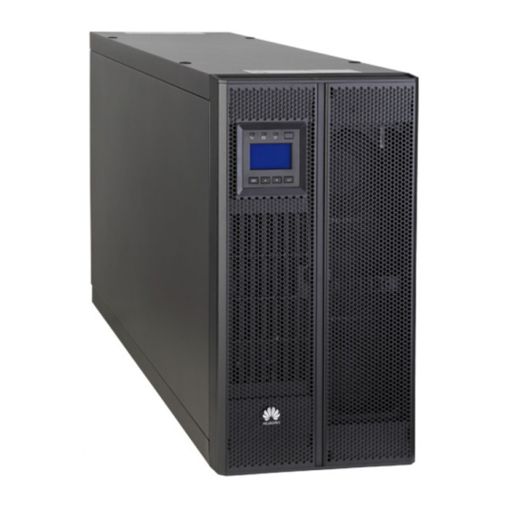
Overview
Model
UPS5000-A-30KTTL
UPS5000-A-40KTTL
MDU
Front panel
NOTE
The right figure shows the UPS with the front panel and MDU removed.
Model
UPS5000-A-60KTTL
UPS5000-A-80KTTL
UPS5000-A-120KTTL
Capacity
Weight
30 kVA,
70 kg
40 kVA
Capacity
60 kVA, 80 kVA
120 kVA
Copyright © Huawei Technologies Co., Ltd. 2019. All rights reserved.
Dimensions (H x W x D)
500 mm x 264 mm x 800 mm (Tower-mounted)
264 mm x 500 mm x 800 mm (Rack-mounted)
Bypass unit
Dimensions (H x W x D)
Weight
160 kg
1020 mm x 440 mm x 850 mm
200 kg
1
Power unit
Advertisement
Table of Contents

Related Manuals for Huawei UPS5000-A-30KTTL


Summary of Contents for Huawei UPS5000-A-30KTTL
- Page 1 UPS5000-A-(30 kVA–120 kVA) Quick Guide Issue: 13 Part Number: 31010NWR Date: 2019-06-28 Copyright © Huawei Technologies Co., Ltd. 2019. All rights reserved. Overview Dimensions (H x W x D) Model Capacity Weight UPS5000-A-30KTTL 30 kVA, 500 mm x 264 mm x 800 mm (Tower-mounted)
-
Page 2: Installing The Ups
2. Use insulated tools during installation. 3. Only engineers certified by Huawei or its agents are allowed to install, commission, and maintain the UPS. Otherwise, personal injury or equipment damage may occur, and the UPS faults caused are beyond the warranty scope of Huawei. - Page 3 3. Push the rear handle back and reinstall the front panel. Scenario 2: Rack-mounted Installation 1. Remove the left and right side panels, the 2. Rotate the ready switches to the unlocked handles, and the MDU of the UPS. state, and remove the power and bypass units. 3.
- Page 4 5. Insert the subrack into the rack and secure it. Insert the power and bypass units into the subrack, and secure the units by using screws. 7. Install the front panel, and rotate the Huawei logo on the front panel 90 degrees clockwise.
- Page 5 60 kVA/80 kVA/120 kVA UPS Scenario 1: Floor Installation Secured Installation 1. Determine the mounting holes based on the 2. Adjust the anchor bolts and ensure that the marking-off template, drill holes, and install anchor bolts touch the floor. Then level the expansion sleeves.
- Page 6 Non-Secured Installation 1. Lower the four leveling feet at the bottom of the cabinet by using a wrench until all the four castors at the bottom hang in the air and the leveling feet bear the whole cabinet weight. 2. Check whether the bottom of the cabinet is horizontal by using a level. If the cabinet is not leveled, adjust the leveling feet.
- Page 7 2. Install floating nuts on both sides at the front of 3. Remove the front cover and power units. the rack. 4. Install mounting ears, and move the chassis into the rack. Floating nuts 5. Adjust the anchor bolts until the bottom of the chassis is aligned with the scale line on the scale plate, and level the UPS.
-
Page 8: Installing Cables
6. Secure the UPS mounting ears to the rack and install the power units in the UPS chassis. Rotate the ready switches on the power units to locked state. Installing Cables UPS Cable Connection Reference • Prepare cables away from the cabinets to prevent scraps from falling inside. Cable scraps may ignite and cause personal injury or device damage. - Page 9 Connecting Cables 30 kVA/40 kVA UPS 1. (Skip this step if the mains and bypass inputs share a power source.) Remove the copper bars between the mains and bypass inputs. 2. Connect the ground cable, power cable, and signal cable. Signal cable Output power cable Battery cable...
- Page 10 The wire routed from the middle point between positive and negative battery strings is the neutral wire. Take a battery string consisting of 40 batteries for example. The battery neutral wire is routed from the middle point between positive and negative battery strings, each consisting of 20 batteries.
- Page 11 4. Connect the ground cable, power cables, and signal cable. Signal cable The number of cables in the figure is for reference only. If the mains input and bypass input share a power source, you do not need to connect bypass input cables.
-
Page 12: Verifying The Installation
Verifying the Installation 1. Check that there is no foreign matter at the top and bottom of the cabinet, copper bars, switches, and the rear of units. 2. After verifying the installation, reinstall all the covers. 3. (Remove the paper protective film from the sealing putty.) After routing cables and verifying cable connections, seal the gap between cables and the cabinet using sealing putty. - Page 13 Powering On the UPS Close the upstream bypass and mains input switches. After the UPS is powered on, initialization begins. The MDU displays the Huawei logo and an initialization progress bar. Setting Key Parameters 1. Set parameters on the Settings Wizard screen. During setting, the Bypass mode and No battery alarms do not need handling if they are triggered.
-
Page 14: Shutting Down The Ups
4. Check that the UPS has transferred to normal mode and that the Bypass mode alarm has disappeared. Use a multimeter to check that the valid three-phase output voltage is 220 V AC, 230 V AC, or 240 V AC and the frequency is 50 Hz or 60 Hz. 5. - Page 15 Scan here for technical support (carrier): Huawei App Store Scan here for more documents: Support-E Support WeChat You can also log in to Huawei technical support website: http://support.huawei.com/enterprise http://support.huawei.com Huawei Technologies Co., Ltd. Huawei Industrial Base, Bantian, Longgang Shenzhen 518129 People's Republic of China...
Need help?
Do you have a question about the UPS5000-A-30KTTL and is the answer not in the manual?
Questions and answers