
Related Manuals for Huawei UPS5000-A-30KTTL


Summary of Contents for Huawei UPS5000-A-30KTTL
- Page 1 UPS5000-A-(30 kVA-120 kVA) User Manual Issue Date 2024-02-21 HUAWEI DIGITAL POWER TECHNOLOGIES CO., LTD.
- Page 2 Notice The purchased products, services and features are stipulated by the contract made between Huawei Digital Power Technologies Co., Ltd. and the customer. All or part of the products, services and features described in this document may not be within the purchase scope or the usage scope. Unless otherwise specified in the contract, all statements, information, and recommendations in this document are provided "AS IS"...
-
Page 3: About This Document
User Manual About This Document About This Document Purpose This document describes the UPS5000-A-30KTTL, UPS5000-A-40KTTL, UPS5000- A-60KTTL, UPS5000-A-80KTTL, UPS5000-A-60KTTL-H, UPS5000-A-120KTTL-H, and UPS5000-A-120KTTL (UPS for short) in terms of product introduction, installation, cable connections, power-on and commissioning, maintenance, troubleshooting, and FAQs. - Page 4 ● Optimized certain operation diagrams. ● Added the requirement for using shielded cables as communications cables. ● Added the notification that a service authorization code needs to be obtained upon the first startup. Issue 17 (2024-02-21) Copyright © Huawei Digital Power Technologies Co., Ltd.
- Page 5 ● Added internal switch specifications to section "Technical Specifications." 2015-06-26 Updated the software version. 2014-09-26 Added the feature of four UPS paralleling and battery monitor unit (BMU). 2014-07-16 Updated the safety information. Issue 17 (2024-02-21) Copyright © Huawei Digital Power Technologies Co., Ltd.
- Page 6 ● Updated chapter "Troubleshooting." 2013-11-18 Added figures of OT and DT terminals for the UPS5000-A and tables that list their specifications. 2013-11-05 This issue is the first official release. Issue 17 (2024-02-21) Copyright © Huawei Digital Power Technologies Co., Ltd.
-
Page 7: Table Of Contents
2.5.1 Power Unit................................... 38 2.5.2 Bypass Unit..................................39 2.5.3 Control Ports..................................40 2.5.4 MDU....................................... 47 2.6 Typical Configurations................................. 49 2.6.1 Single UPS.................................... 49 2.6.2 Parallel System................................... 50 2.6.3 Dual-Bus System................................50 Issue 17 (2024-02-21) Copyright © Huawei Digital Power Technologies Co., Ltd. - Page 8 5.1 Powering On and Starting the UPS..........................121 5.1.1 Power-On................................... 121 5.1.2 Initial Startup..................................122 5.1.3 Powering On Loads................................ 123 5.2 Setting the T/H Sensor..............................124 5.3 Setting BCB Parameters..............................126 Issue 17 (2024-02-21) Copyright © Huawei Digital Power Technologies Co., Ltd.
- Page 9 9.3 Transferring to Maintenance Bypass Mode....................... 160 9.4 Transferring from Maintenance Bypass Mode to Normal Mode............... 161 9.5 Performing EPO...................................162 9.6 Clearing the EPO State..............................163 A Acronyms and Abbreviations................... 164 Issue 17 (2024-02-21) Copyright © Huawei Digital Power Technologies Co., Ltd. viii...
-
Page 10: Safety Information
Equipment damage due to force majeure such as earthquakes, floods, volcanic eruptions, debris flows, lightning strikes, fires, wars, armed conflicts, typhoons, hurricanes, tornadoes, and extreme weather conditions ● Operation beyond the conditions specified in this document Issue 17 (2024-02-21) Copyright © Huawei Digital Power Technologies Co., Ltd. -
Page 11: Personal Safety
D ANGER During operations, use dedicated insulated tools to prevent electric shocks or short circuits. The insulation and voltage resistance must comply with local laws, regulations, standards, and specifications. Issue 17 (2024-02-21) Copyright © Huawei Digital Power Technologies Co., Ltd. - Page 12 – Trained personnel: personnel who are trained in technology and safety, have required experience, are aware of possible hazards on themselves in Issue 17 (2024-02-21) Copyright © Huawei Digital Power Technologies Co., Ltd.
-
Page 13: Equipment Safety
Issue 17 (2024-02-21) Copyright © Huawei Digital Power Technologies Co., Ltd. -
Page 14: Battery Safety
Do not expose batteries at high temperatures or around heat sources, such as scorching sunlight, fire sources, transformers, and heaters. Battery overheating may cause leakage, smoke, flammable gas release, thermal runaway, fire, or explosion. Issue 17 (2024-02-21) Copyright © Huawei Digital Power Technologies Co., Ltd. - Page 15 Ensure that no liquid enters the equipment to prevent faults or short circuits. Issue 17 (2024-02-21) Copyright © Huawei Digital Power Technologies Co., Ltd.
- Page 16 After batteries are discharged, charge them in time to avoid damage due to overdischarge. WARNING If the electrolyte leaks, absorb and neutralize the electrolyte immediately. Exercise caution when moving or handling a lead-acid battery with electrolyte leakage to avoid electrolyte hazards. Issue 17 (2024-02-21) Copyright © Huawei Digital Power Technologies Co., Ltd.
- Page 17 – Batteries are not transported, stored, or charged according to the instructions in the user manual. – Instructions from the Company are not followed during battery relocation or reinstallation. Issue 17 (2024-02-21) Copyright © Huawei Digital Power Technologies Co., Ltd.
- Page 18 ● Check whether the positive and negative battery terminals are grounded unexpectedly. If so, disconnect the battery terminals from the ground. Issue 17 (2024-02-21) Copyright © Huawei Digital Power Technologies Co., Ltd.
- Page 19 Intake: Seek immediate medical attention. Special requirements for lead-acid batteries: NO TICE When the battery temperature exceeds 60°C, check whether the electrolyte leaks. If the electrolyte leaks, take proper measures promptly. Issue 17 (2024-02-21) Copyright © Huawei Digital Power Technologies Co., Ltd.
-
Page 20: Electrical Safety
WARNING For the equipment that needs to be grounded, install the ground cable first when installing the equipment and remove the ground cable last when removing the equipment. Issue 17 (2024-02-21) Copyright © Huawei Digital Power Technologies Co., Ltd. - Page 21 (The marks must cross the edges of the bolts.) ● After the installation is complete, ensure that protective cases, insulation tubes, and other necessary items for all electrical components are in position to avoid electric shocks. Issue 17 (2024-02-21) Copyright © Huawei Digital Power Technologies Co., Ltd.
- Page 22 When selecting, installing, and routing cables, follow local safety regulations and rules. ● The flame spread rating of cables shall meet the UL 1581 VW-1 or IEC 60332-3-22 (ZB) or higher requirements. Issue 17 (2024-02-21) Copyright © Huawei Digital Power Technologies Co., Ltd.
- Page 23 When touching the equipment and handling boards, modules with exposed circuit boards, or application-specific integrated circuits (ASICs), observe ESD protection regulations and wear ESD clothing and ESD gloves or a well- grounded ESD wrist strap. Issue 17 (2024-02-21) Copyright © Huawei Digital Power Technologies Co., Ltd.
-
Page 24: Environmental Requirements
Ensure that no liquid enters the equipment to prevent faults or short circuits. Issue 17 (2024-02-21) Copyright © Huawei Digital Power Technologies Co., Ltd. - Page 25 All cable holes must be sealed. Seal the used cable holes with sealing putty. Seal the unused cable holes with the caps delivered with the equipment. The following figure shows the criteria for correct sealing with sealing putty. Issue 17 (2024-02-21) Copyright © Huawei Digital Power Technologies Co., Ltd.
-
Page 26: Mechanical Safety
Otherwise, tipping or falling cabinets may cause bodily injury and equipment damage. WARNING When pulling equipment out of a cabinet, be aware of unstable or heavy objects in the cabinet to prevent injury. Issue 17 (2024-02-21) Copyright © Huawei Digital Power Technologies Co., Ltd. - Page 27 Issue 17 (2024-02-21) Copyright © Huawei Digital Power Technologies Co., Ltd.
- Page 28 Personnel involving working at heights are not allowed to throw objects from the height to the ground, or vice versa. Objects shall be transported by slings, hanging baskets, aerial work platforms, or cranes. Issue 17 (2024-02-21) Copyright © Huawei Digital Power Technologies Co., Ltd.
- Page 29 If a single ladder is used, the recommended angle for the ladder against the floor is 75 degrees, as shown in the following figure. A square can be used to measure the angle. Issue 17 (2024-02-21) Copyright © Huawei Digital Power Technologies Co., Ltd.
- Page 30 Do not drag steel ropes and hoisting tools or bump hoisted objects against hard objects during hoisting. ● Ensure that the angle between two hoisting ropes is no more than 90 degrees, as shown in the following figure. Issue 17 (2024-02-21) Copyright © Huawei Digital Power Technologies Co., Ltd.
- Page 31 To avoid short circuits or other risks, do not drill holes into buried pipes or cables. ● When drilling holes, protect the equipment from shavings. After drilling, clean up any shavings. Issue 17 (2024-02-21) Copyright © Huawei Digital Power Technologies Co., Ltd.
-
Page 32: Product Overview
● UPS5000-A-30KTTL ● UPS5000-A-40KTTL ● UPS5000-A-60KTTL ● UPS5000-A-80KTTL ● UPS5000-A-60KTTL-H ● UPS5000-A-120KTTL-H ● UPS5000-A-120KTTL Figure 2-1 UPS model number Meaning Value Product category UPS family 5000 A series subcategory Issue 17 (2024-02-21) Copyright © Huawei Digital Power Technologies Co., Ltd. -
Page 33: Working Principle
2.3.1 Normal Mode The normal mode indicates that the UPS works normally: The rectifier converts the AC input voltage into the DC voltage, which is then raised to the bus voltage Issue 17 (2024-02-21) Copyright © Huawei Digital Power Technologies Co., Ltd. -
Page 34: Bypass Mode
The power supply in bypass mode is not protected by the UPS and therefore tends to be affected by the mains outage and abnormal AC voltage waveform or frequency. Figure 2-4 Bypass mode Issue 17 (2024-02-21) Copyright © Huawei Digital Power Technologies Co., Ltd. -
Page 35: Battery Mode
2.3.5 ECO Mode The economic control operation (ECO) mode is an energy-saving mode, which you can configure on the liquid crystal display (LCD) or web user interface (WebUI). In Issue 17 (2024-02-21) Copyright © Huawei Digital Power Technologies Co., Ltd. -
Page 36: Chassis Description
In either bypass mode or normal mode, the rectifier keeps working and charges batteries over a charger. The ECO mode guarantees high efficiency. Figure 2-7 ECO mode 2.4 Chassis Description Issue 17 (2024-02-21) Copyright © Huawei Digital Power Technologies Co., Ltd. -
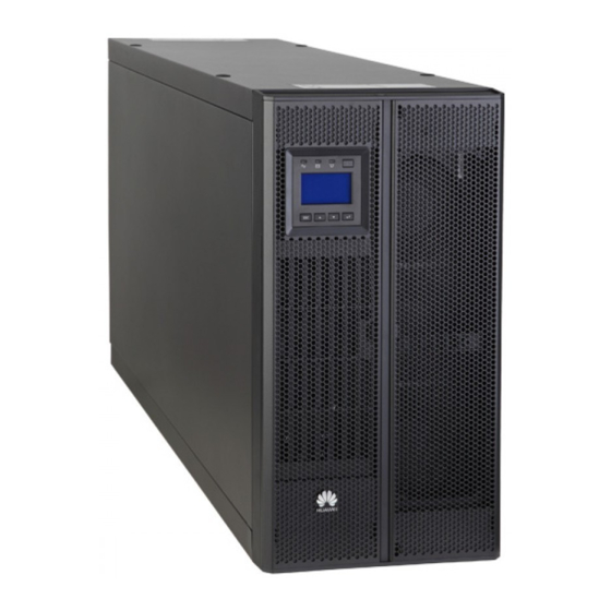
Page 37: Kva/40 Kva
(1) Monitoring display unit (MDU) (2) Front panel (3) Support base (4) Chassis Front View NO TE The right view shows the device with the front panel and MDU removed. Issue 17 (2024-02-21) Copyright © Huawei Digital Power Technologies Co., Ltd. - Page 38 (2) Maintenance bypass switch (3) UPS output terminals (under the cover) (4) Battery wiring terminals (5) UPS bypass input terminals (6) UPS mains input terminals (under the cover) (under the cover) (under the cover) Issue 17 (2024-02-21) Copyright © Huawei Digital Power Technologies Co., Ltd.
-
Page 39: Kva
(2) MDU (3) Front panel 2 (4) Leveling foot (5) Chassis (6) Castor Front View NO TE The right view shows the device with the front panel and MDU removed. Issue 17 (2024-02-21) Copyright © Huawei Digital Power Technologies Co., Ltd. - Page 40 (BOM number: 02290795) numbers: 02290376 and 02291237) 02311GNY) (1) Bypass unit 3 (BOM (2) Power unit (3) Maintenance bypass switch number: 02313XPE) (4) Bypass unit 4 (BOM number: 02310UCJ) Issue 17 (2024-02-21) Copyright © Huawei Digital Power Technologies Co., Ltd.
- Page 41 UPS5000-A-(30 kVA-120 kVA) User Manual 2 Product Overview Rear View Figure 2-13 Rear view (60 kVA) (1) Control ports (2) Power distribution unit (PDU) Issue 17 (2024-02-21) Copyright © Huawei Digital Power Technologies Co., Ltd.
-
Page 42: Kva
(2) MDU (3) Front panel 2 (4) Leveling foot (5) Chassis (6) Castor Front View NO TE The right view shows the device with the front panel and MDU removed. Issue 17 (2024-02-21) Copyright © Huawei Digital Power Technologies Co., Ltd. - Page 43 UPS5000-A-(30 kVA-120 kVA) User Manual 2 Product Overview Figure 2-15 Front view (80 kVA) (1) Bypass unit 4 (2) Power units (3) Maintenance bypass switch Issue 17 (2024-02-21) Copyright © Huawei Digital Power Technologies Co., Ltd.
- Page 44 UPS5000-A-(30 kVA-120 kVA) User Manual 2 Product Overview Rear View Figure 2-16 Rear view (80 kVA) (1) Control ports (2) PDU Issue 17 (2024-02-21) Copyright © Huawei Digital Power Technologies Co., Ltd.
-
Page 45: Kva
(2) MDU (3) Front panel 2 (4) Leveling foot (5) Chassis (6) Castor Front View NO TE The right view shows the device with the front panel and MDU removed. Issue 17 (2024-02-21) Copyright © Huawei Digital Power Technologies Co., Ltd. - Page 46 UPS5000-A-(30 kVA-120 kVA) User Manual 2 Product Overview Figure 2-18 Front view (120 kVA) (A) UPS5000-A-120KTTL-H (B) UPS5000-A-120KTTL (1) Bypass unit 4 (2) Power units (3) Maintenance bypass switch Issue 17 (2024-02-21) Copyright © Huawei Digital Power Technologies Co., Ltd.
-
Page 47: Component Description
2.5 Component Description 2.5.1 Power Unit NO TE The layout of the power unit varies depending on the chassis. The following figure uses the 30 kVA UPS as an example. Issue 17 (2024-02-21) Copyright © Huawei Digital Power Technologies Co., Ltd. -
Page 48: Bypass Unit
(1) Running indicator (2) Alarm indicator (3) Fault indicator (4) Ready switch (5) MDU reset button (6) DIP switches (7) USB port (reserved) (8) MDU port (9) Battery cold start button Issue 17 (2024-02-21) Copyright © Huawei Digital Power Technologies Co., Ltd. -
Page 49: Control Ports
CAN2 build-out resistor for rack parallel connection 2.5.3 Control Ports The UPS provides the communications slot, FE port, RS485 port, parallel port, BSC port, basic dry contacts, and other control signal ports. Issue 17 (2024-02-21) Copyright © Huawei Digital Power Technologies Co., Ltd. - Page 50 The BSC port is used in a multi-bus system to synchronize output frequencies and phases among UPS systems, ensuring that multiple buses can switch between each other. BSC cables are hot-swappable. Issue 17 (2024-02-21) Copyright © Huawei Digital Power Technologies Co., Ltd.
- Page 51 Port for signal alarm. no battery ground grounding fault The value can be changed to Closed: ● BTG port open: battery grounding fault ● BTG port closed: no battery grounding fault Issue 17 (2024-02-21) Copyright © Huawei Digital Power Technologies Co., Ltd.
- Page 52 Used to send a ground tripped BCB tripping drive signal. ● 12 V: BCB BCB_DRV Port for tripped controlling BCB trip. When the voltage is +12 V, the BCB trips. Issue 17 (2024-02-21) Copyright © Huawei Digital Power Technologies Co., Ltd.
- Page 53 OFF. The value can be changed to Closed: ● MT port closed: The PDC maintenance switch is ON. ● MT port open: The PDC maintenance switch is OFF. Issue 17 (2024-02-21) Copyright © Huawei Digital Power Technologies Co., Ltd.
- Page 54 When connecting the dry contact signal cable of an external device to a UPS dry contact, ensure that the silk screens of the dry contacts at both ends of the cable are consistent. Issue 17 (2024-02-21) Copyright © Huawei Digital Power Technologies Co., Ltd.
- Page 55 ● Connects to a third-party network communication management device over two wires. s port ● Supported protocol: Modbus-RTU Table 2-2 Pin definitions for the COM1 port Appearance COM1 Port RS485_R– RS485_R+ 12V_PORT Issue 17 (2024-02-21) Copyright © Huawei Digital Power Technologies Co., Ltd.
-
Page 56: Mdu
Figure 2-24 Appearance (1) LCD (2) Back/Shutdown button (3) Up button (4) Down button (5) Enter/Startup/Mute button (6) Fault indicator/INFO button (7) Bypass indicator (8) Battery indicator (9) Mains indicator Issue 17 (2024-02-21) Copyright © Huawei Digital Power Technologies Co., Ltd. - Page 57 When the buzzer buzzes, hold down the button for more than 2s and then release the button to mute the buzzer. The sound generated due to low battery reserve cannot be muted by this button. Issue 17 (2024-02-21) Copyright © Huawei Digital Power Technologies Co., Ltd.
-
Page 58: Typical Configurations
The UPS5000-A is a series of transformerless tower-mount UPSs. This series uses the unit-level design for its power part with an embedded maintenance bypass switch, enabling maintenance with power on. Issue 17 (2024-02-21) Copyright © Huawei Digital Power Technologies Co., Ltd. -
Page 59: Parallel System
An optional static transfer switch (STS) can be installed to start the bus synchronization controller (BSC). The UPS systems work in inverter mode or bypass mode. Issue 17 (2024-02-21) Copyright © Huawei Digital Power Technologies Co., Ltd. -
Page 60: Optional Components
● PDU8000-1250DCV8-BGA001 ● PDU8000-2000DCV8-BGA001 Antiseismic kit Reinforces the cabinet so that the cabinet can resist intensity 9 earthquakes. Dry contact card RMS-RELAY01A Provides output dry contacts. Issue 17 (2024-02-21) Copyright © Huawei Digital Power Technologies Co., Ltd. - Page 61 Connects UPSs in a parallel system. BSC cable 15 m Transmits bus synchronization signals in a dual-bus system. NO TE Antiseismic kits can be installed only for 60 kVA/80 kVA/120 kVA UPSs. Issue 17 (2024-02-21) Copyright © Huawei Digital Power Technologies Co., Ltd.
-
Page 62: Technical Specifications
60 kVA 80 kVA 120 kVA Maintenance 750 V AC/80 750 V AC/80 750 V AC/160 750 V AC/160 1000 V bypass switch A/3P A/3P A/3P A/3P AC/200 A/3P Issue 17 (2024-02-21) Copyright © Huawei Digital Power Technologies Co., Ltd. -
Page 63: Environmental Specifications
Conducted emission EN/IEC 62040-2 (CE) Radiated emission (RE) EN/IEC 62040-2 Harmonic current IEC 61000-3-12 Voltage fluctuation and IEC 61000-3-11 flicker Low-frequency signal IEC 61000-2-2 interference ESD immunity IEC 61000-4-2 Issue 17 (2024-02-21) Copyright © Huawei Digital Power Technologies Co., Ltd. -
Page 64: Mains Input Electrical Specifications
– 30–40°C: not derated at 187–280 V AC; derated to 40% load at 187–80 V AC – 0–30°C: not derated at 176–280 V AC; derated to 40% load at 176–80 V AC Issue 17 (2024-02-21) Copyright © Huawei Digital Power Technologies Co., Ltd. -
Page 65: Bypass Input Electrical Specifications
±6 Hz (adjustable, 0.5–6 Hz, ±2 Hz by default) Input system The mains input and bypass input can share a power source or use different power sources. Overvoltage category OVC II 3.7 Battery Specifications Issue 17 (2024-02-21) Copyright © Huawei Digital Power Technologies Co., Ltd. -
Page 66: Output Electrical Specifications
Frequency In normal mode, the mains frequency is synchronous with the bypass input frequency. In battery mode, the frequency is 50 Hz/60 Hz with a tolerance of ±0.05%. Issue 17 (2024-02-21) Copyright © Huawei Digital Power Technologies Co., Ltd. -
Page 67: System Electrical Specifications
– Load > 150% or a short circuit occurs: run for 200 ms Inverter 151 A output short-circuit capability 3.9 System Electrical Specifications Item Specifications Parallel system Redundancy design for parallel signals reliability Issue 17 (2024-02-21) Copyright © Huawei Digital Power Technologies Co., Ltd. - Page 68 Item Specifications ECO function Supported No-load loss ● UPS5000-A-30KTTL (BOM numbers: 02291114 and 02291235), UPS5000-A-40KTTL (BOM numbers: 02291115 and 02291236), and UPS5000-A-60KTTL-H: 1.5 kW ● UPS5000-A-120KTTL-H: 2 kW ● UPS5000-A-30KTTL (BOM numbers: 02290371 and 02311GNW), UPS5000-A-40KTTL (BOM numbers: 02290372 and 02311GNX), UPS5000-A-80KTTL, and UPS5000-A-120KTTL: <...
-
Page 69: Installation And Cable Connection
Reserve a clearance of at least 800 mm if you need to perform operations at the rear of the cabinet. The figure uses a 30 kVA/40 kVA UPS as an example. Issue 17 (2024-02-21) Copyright © Huawei Digital Power Technologies Co., Ltd. -
Page 70: Tools
The onsite operation personnel can select tools based on the site requirements. Personal Protective Equipment Safety helmet Goggles Protective shoes Reflective vest ESD gloves Insulated gloves Protective gloves Safety harness Issue 17 (2024-02-21) Copyright © Huawei Digital Power Technologies Co., Ltd. - Page 71 Insulated torque Hex key insulated torque torque socket wrench screwdriver screwdriver Including (M2.5) (M4/M5/M6) extended sockets (M8/M10/M12/ M16) Adjustable torque Hammer drill Hammer drill bit Claw hammer wrench (Φ16 mm) Issue 17 (2024-02-21) Copyright © Huawei Digital Power Technologies Co., Ltd.
- Page 72 Cable Installation Tools Cable cutter Wire stripper Diagonal pliers RJ45 crimping tool Electro-hydraulic Cord end terminal Heat gun Scissors pliers crimping tool Measurement Instruments Height gauge Laser locator Electroprobe Thermometer Issue 17 (2024-02-21) Copyright © Huawei Digital Power Technologies Co., Ltd.
- Page 73 Level Laptop Level gauge Multimeter Network tester Phase sequence Dielectric strength Megohmmeter meter tester Machinery Small cutter Cable reel Engineering Auxiliary Materials Label Cable tie Cotton cloth Sandpaper Issue 17 (2024-02-21) Copyright © Huawei Digital Power Technologies Co., Ltd.
-
Page 74: Preparing Power Cables
RCD is not recommended. ● If multiple UPSs are to be connected in parallel, input and output power cables for each UPS should have the same length and specifications. Issue 17 (2024-02-21) Copyright © Huawei Digital Power Technologies Co., Ltd. - Page 75 4 x 70 nded cross- sectional area Output Output current (A) Recomme 4 x 10 4 x 16 4 x 25 4 x 35 4 x 70 nded cross- sectional area Issue 17 (2024-02-21) Copyright © Huawei Digital Power Technologies Co., Ltd.
- Page 76 3 x 150 nded cross- sectional area Ground Recomme 1 x 10 1 x 16 1 x 16 1 x 25 1 x 50 cable nded cross- sectional area Issue 17 (2024-02-21) Copyright © Huawei Digital Power Technologies Co., Ltd.
- Page 77 1.5–1.7 times. CA UTION When you connect power cables, comply with the tightening torque listed in the following table to ensure secure connections and prevent safety risks. Issue 17 (2024-02-21) Copyright © Huawei Digital Power Technologies Co., Ltd.
- Page 78 120 kVA Crimped DT terminal 11 mm 27 N·m 30–40 kVA Crimped OT terminal 6.5 mm 4.5 N·m 60–120 Crimped DT terminal 9 mm 13 N·m Figure 4-2 OT terminal Issue 17 (2024-02-21) Copyright © Huawei Digital Power Technologies Co., Ltd.
- Page 79 (mm) Nomina Devi Nomi Deviat Referenc Nomin Devi or Size r (mm) l Value ation e Value ation Value Value ±0.30 0–0.12 ±1.50 0–0.16 ±0.40 10.5 10.5 ±0.50 0–0.24 Issue 17 (2024-02-21) Copyright © Huawei Digital Power Technologies Co., Ltd.
- Page 80 T1N160 TMD R125 3P FFC ABB (recommended when the short-circuit current where 120 kVA T3N250 TMD R200 3P FF the circuit breaker is located is less than 36 kA) Issue 17 (2024-02-21) Copyright © Huawei Digital Power Technologies Co., Ltd.
-
Page 81: Transportation, Unpacking, And Checking
Step 1 Verify that the UPS packing case is not damaged. If any damage is found, report it to the carrier immediately. Step 2 Use a forklift to transport the UPS to the installation position. Step 3 Cut off and remove the binding straps. Issue 17 (2024-02-21) Copyright © Huawei Digital Power Technologies Co., Ltd. - Page 82 Visually inspect the UPS appearance for shipping damage. If any damage is found, notify the carrier immediately. Check that the fittings comply with the packing list. If there is any discrepancy, keep a record and contact the supplier immediately. Issue 17 (2024-02-21) Copyright © Huawei Digital Power Technologies Co., Ltd.
-
Page 83: Kva/80 Kva/120 Kva Ups
Step 3 Hold the sliding plate steady. Cut and remove the binding straps. Put down the sliding plate gently. Figure 4-6 Removing binding straps Step 4 Remove the packing materials and foam. Issue 17 (2024-02-21) Copyright © Huawei Digital Power Technologies Co., Ltd. - Page 84 Remove the screws that secure the lower front panel. Remove the ground cable between the lower front panel and the chassis, and remove the lower front panel. Issue 17 (2024-02-21) Copyright © Huawei Digital Power Technologies Co., Ltd.
- Page 85 Step 8 Remove the L-shaped brackets that secure the chassis and pallet. Figure 4-9 Removing the L-shaped brackets NO TE Store the removed L-shaped brackets, which will be used to secure the UPS. Issue 17 (2024-02-21) Copyright © Huawei Digital Power Technologies Co., Ltd.
-
Page 86: Single Ups Installation
Step 2 Pull out the rear handle from the device. Loosen the screws on the back-end handle anticlockwise. Pull the handle out of the groove until the positioning kit is exposed. Issue 17 (2024-02-21) Copyright © Huawei Digital Power Technologies Co., Ltd. - Page 87 Each group of devices require two support bases, and the distance between support bases must be greater than 480 mm. Figure 4-12 Placing the UPS on the support bases (unit: mm) Issue 17 (2024-02-21) Copyright © Huawei Digital Power Technologies Co., Ltd.
- Page 88 Figure 4-14 Installing the front panel Step 6 To prevent misoperations, you are advised to install a lock (diameter of the effective lock cylinder: 5–6.3 mm) for the maintenance bypass switch. Issue 17 (2024-02-21) Copyright © Huawei Digital Power Technologies Co., Ltd.
- Page 89 Step 2 Flip the ready switches on the power unit and bypass unit to (not ready). Remove the screws from the mounting ears of the bypass unit, and remove the power unit and bypass unit. Issue 17 (2024-02-21) Copyright © Huawei Digital Power Technologies Co., Ltd.
- Page 90 NO TICE Ensure that the lower edge of the guide rail is aligned with the lower edge of a U scale. Issue 17 (2024-02-21) Copyright © Huawei Digital Power Technologies Co., Ltd.
- Page 91 Secure the back end of the guide rail using panel screws. Do not secure the front end of the guide rail. Install the other guide rail in the same method. Issue 17 (2024-02-21) Copyright © Huawei Digital Power Technologies Co., Ltd.
- Page 92 Step 4 Insert the chassis into the rack and secure the front end of the guide rail using panel screws. Figure 4-22 Position of the subrack Step 5 Replace the mounting ears on the left and right sides of the power unit. Issue 17 (2024-02-21) Copyright © Huawei Digital Power Technologies Co., Ltd.
- Page 93 Step 6 Reinstall and secure the power unit and bypass unit, and flip all ready switches to (ready). Figure 4-24 Reinstalling the power unit and bypass unit Step 7 Rotate the removed MDU 90 degrees clockwise, install it with the support, and connect cables. Issue 17 (2024-02-21) Copyright © Huawei Digital Power Technologies Co., Ltd.
- Page 94 Step 8 Install the front panel, and rotate the logo on the front panel 90 degrees clockwise. Figure 4-26 Installing the front panel Step 9 (Recommended) Install a lock for the maintenance bypass switch, as shown in Figure 4-15. ----End Issue 17 (2024-02-21) Copyright © Huawei Digital Power Technologies Co., Ltd.
-
Page 95: Cable Routing Requirements
Step 4 Connect the cable with a crimped terminal to the corresponding copper bar. Step 5 Bind the cable to the nearby beam. Step 6 Clear sundries inside the cabinet. ----End Issue 17 (2024-02-21) Copyright © Huawei Digital Power Technologies Co., Ltd. -
Page 96: Installing Cables
The number and colors of cables in the following figures are for reference only. Procedure Step 1 Remove the terminal block cover. Figure 4-29 Removing the cover Step 2 Install ground cables. Issue 17 (2024-02-21) Copyright © Huawei Digital Power Technologies Co., Ltd. - Page 97 ● : protective ground label Step 3 Install UPS output power cables. Figure 4-31 Connecting output power cables Step 4 Install AC input power cables. ● One power source Issue 17 (2024-02-21) Copyright © Huawei Digital Power Technologies Co., Ltd.
- Page 98 Figure 4-32 Installing AC input power cables ● Two power sources Remove the copper bars connecting mains and bypass inputs. Figure 4-33 Removing copper bars Install AC input power cables. Issue 17 (2024-02-21) Copyright © Huawei Digital Power Technologies Co., Ltd.
- Page 99 Take a battery string consisting of 40 batteries for example. The battery neutral wire is routed from the middle of positive and negative battery strings, each consisting of 20 batteries. Issue 17 (2024-02-21) Copyright © Huawei Digital Power Technologies Co., Ltd.
-
Page 100: Installing A Remote Epo Switch
NO TE RS485 cables and FE cables must be shielded cables. Figure 4-37 Cable route (1) Communications cable route ----End 4.2.1.4 Installing a Remote EPO Switch Issue 17 (2024-02-21) Copyright © Huawei Digital Power Technologies Co., Ltd. -
Page 101: Single Ups Installation (60 Kva/80 Kva/120 Kva)
Step 1 Lower the four leveling feet at the bottom of the cabinet using a wrench until all the four castors at the bottom hang in the air and the leveling feet bear the whole cabinet weight. Issue 17 (2024-02-21) Copyright © Huawei Digital Power Technologies Co., Ltd. - Page 102 5–10 mm) for the maintenance bypass switch. Figure 4-40 Lock for the maintenance bypass switch ----End Tower-mounted Installation (Secured Installation) Step 1 Determine the position for installing the UPS and mark mounting holes. Issue 17 (2024-02-21) Copyright © Huawei Digital Power Technologies Co., Ltd.
- Page 103 Knock the expansion bolt into the hole until the expansion sleeve completely fits into the hole. The expansion sleeve must be completely buried under the ground to facilitate subsequent installation. Issue 17 (2024-02-21) Copyright © Huawei Digital Power Technologies Co., Ltd.
- Page 104 Secure the two L-shaped brackets to the floor. Figure 4-43 Installing L-shaped brackets Step 6 Reinstall the ground cable between the lower front panel and the chassis, and reinstall the lower front panel. Issue 17 (2024-02-21) Copyright © Huawei Digital Power Technologies Co., Ltd.
- Page 105 Level the bottom plane of a guide rail with the lower edge of U scale 01, and engage the mounting ears on both ends of the guide rail into the mounting holes of the mounting bar. Issue 17 (2024-02-21) Copyright © Huawei Digital Power Technologies Co., Ltd.
- Page 106 Step 2 Install a stiffening beam at the front and rear of the rack respectively. After the installation is complete, tighten the panel screws that secure the guide rails. Issue 17 (2024-02-21) Copyright © Huawei Digital Power Technologies Co., Ltd.
- Page 107 Level the Bottom line on the scale plate with the lower edge of U sale 01 on the rack. Install floating nuts onto the mounting holes for the mounting bar that corresponds to Hole location lines. Issue 17 (2024-02-21) Copyright © Huawei Digital Power Technologies Co., Ltd.
- Page 108 Step 4 Flip the ready switches on the power units to (not ready), and remove the power units. NO TICE Two persons are required to move a power unit. Keep the power unit horizontal during movement. Issue 17 (2024-02-21) Copyright © Huawei Digital Power Technologies Co., Ltd.
- Page 109 Step 6 Adjust the four leveling feet using an adjustable wrench until the bottom of the UPS is level with the Edge of cabinet line on the scale plate, and level the UPS chassis. Issue 17 (2024-02-21) Copyright © Huawei Digital Power Technologies Co., Ltd.
- Page 110 Step 10 Reinstall the upper front panel. Step 11 (Recommended) Install a lock for the maintenance bypass switch, as shown in Figure 4-40. ----End Issue 17 (2024-02-21) Copyright © Huawei Digital Power Technologies Co., Ltd.
-
Page 111: Installing Antiseismic Kits
Secure the front and rear antiseismic kits to the floor. Figure 4-53 Securing antiseismic kits Step 6 Reinstall the UPS front panel and PDU cover. ----End Issue 17 (2024-02-21) Copyright © Huawei Digital Power Technologies Co., Ltd. -
Page 112: Cable Routing Requirements
Step 4 Connect the cable with a crimped terminal to the corresponding copper bar. Step 5 Bind the cable to the nearby beam. Step 6 Clear sundries inside the cabinet. ----End Issue 17 (2024-02-21) Copyright © Huawei Digital Power Technologies Co., Ltd. -
Page 113: Installing Cables
UPS except for the size of some screws. The number and colors of cables in the following figures are for reference only. Procedure Step 1 Remove the PDU cover from the rear of the chassis. Issue 17 (2024-02-21) Copyright © Huawei Digital Power Technologies Co., Ltd. - Page 114 Step 2 Remove the small covers from the bottom of the chassis based on the number and positions of cables. Figure 4-57 Removing small covers Step 3 Install ground cables. Issue 17 (2024-02-21) Copyright © Huawei Digital Power Technologies Co., Ltd.
- Page 115 Figure 4-58 Installing ground cables NO TE ● : internal equipotential bonding label ● : protective ground label Step 4 Install UPS output power cables. Figure 4-59 Connecting output power cables Issue 17 (2024-02-21) Copyright © Huawei Digital Power Technologies Co., Ltd.
- Page 116 Figure 4-60 Installing AC input power cables ● Two power sources Remove the copper bars connecting mains and bypass inputs. Figure 4-61 Removing copper bars Install AC input power cables. Issue 17 (2024-02-21) Copyright © Huawei Digital Power Technologies Co., Ltd.
- Page 117 Take a battery string consisting of 40 batteries for example. The battery neutral wire is routed from the middle of positive and negative battery strings, each consisting of 20 batteries. Issue 17 (2024-02-21) Copyright © Huawei Digital Power Technologies Co., Ltd.
- Page 118 If the UPS needs to connect to an external network management device, connect the external network management device to the RS485 port on the monitoring interface card. NO TE RS485 cables and FE cables must be shielded cables. Issue 17 (2024-02-21) Copyright © Huawei Digital Power Technologies Co., Ltd.
-
Page 119: Installing A Remote Epo Switch
Connect the EPO switch to the dry contact on the UPS using a cable. The EPO port is normally open (NO) by default. When you turn on the EPO switch, EPO is triggered. Issue 17 (2024-02-21) Copyright © Huawei Digital Power Technologies Co., Ltd. -
Page 120: Installing T/H Sensors And Cables
Connect the RS485-OUT port on the T/H sensor to the RS485-IN port on another T/H sensor. Figure 4-67 Connecting cables (1) Cascaded with another T/H sensor NO TE The UPS can connect to a maximum of 12 cascaded T/H sensors. Issue 17 (2024-02-21) Copyright © Huawei Digital Power Technologies Co., Ltd. -
Page 121: Installing A Parallel System
Step 1 Ground each UPS in a parallel system separately, and connect power cables and battery cables. Step 2 Select a parallel mode and connect cables to the parallel system based on site requirements. Issue 17 (2024-02-21) Copyright © Huawei Digital Power Technologies Co., Ltd. - Page 122 ● Do not configure circuit breakers for the mains and bypass input N wires and output N wire. ● Connect power cables according to the silk screen on the terminals. Figure 4-68 Conceptual diagram of a 1+1 parallel system Issue 17 (2024-02-21) Copyright © Huawei Digital Power Technologies Co., Ltd.
- Page 123 Figure 4-70 Cable connections for a 1+1 parallel system (60 kVA/80 kVA/120 kVA) (1) Mains input power (2) Bypass input power (3) Battery cables (4) Output power cables cables cables Issue 17 (2024-02-21) Copyright © Huawei Digital Power Technologies Co., Ltd.
- Page 124 Figure 4-71 Conceptual diagram of a dual-bus system Figure 4-72 Cable connections for a dual-bus system (30 kVA/40 kVA) (1) Mains input power (2) Bypass input power (3) Battery cables (4) Output power cables cables cables Issue 17 (2024-02-21) Copyright © Huawei Digital Power Technologies Co., Ltd.
-
Page 125: Verifying The Installation
The system configurations, including system configuration and models and the number of units, comply the product delivery with the contract. Cable layout Cables are routed properly and meet engineering requirements. Issue 17 (2024-02-21) Copyright © Huawei Digital Power Technologies Co., Ltd. - Page 126 (2 V or 12 V). Issue 17 (2024-02-21) Copyright © Huawei Digital Power Technologies Co., Ltd.
- Page 127 Do not remove the transparent film. ● If the sealing putty covers the aluminum foil film, do not cut the sealing putty. ● After verifying the installation, reinstall all the covers. Issue 17 (2024-02-21) Copyright © Huawei Digital Power Technologies Co., Ltd.
- Page 128 4 Installation and Cable Connection Figure 4-74 30 kVA/40 kVA UPS (1) Wiring terminals (2) Wiring terminal box Figure 4-75 60 kVA/80 kVA/120 kVA UPS (1) Wiring terminals (2) UPS bottom Issue 17 (2024-02-21) Copyright © Huawei Digital Power Technologies Co., Ltd.
- Page 129 4 Installation and Cable Connection Figure 4-76 Filling a gap with sealing putty (1) Paper protective film (2) Transparent film (3) Sealing putty (with the transparent film facing upward) Issue 17 (2024-02-21) Copyright © Huawei Digital Power Technologies Co., Ltd.
-
Page 130: Single Ups Commissioning
Step 1 If desiccant is available inside the cabinets, remove the desiccant. Step 2 Turn on the upstream bypass and mains input switches. After the UPS is powered on, initialization begins. The MDU displays the initialization progress bar. ----End Issue 17 (2024-02-21) Copyright © Huawei Digital Power Technologies Co., Ltd. -
Page 131: Initial Startup
● Set Output frequency correctly. Otherwise, loads may be affected and the UPS may not work properly. ● Set all battery parameters correctly based on site requirements. Battery parameter settings are critical to battery maintenance, battery lifespan, and UPS discharge time. Issue 17 (2024-02-21) Copyright © Huawei Digital Power Technologies Co., Ltd. -
Page 132: Powering On Loads
UPS works in bypass mode. ----End 5.1.3 Powering On Loads Context After the inverter starts, the UPS transfers to inverter mode, and the Bypass mode alarm on the MDU disappears. Issue 17 (2024-02-21) Copyright © Huawei Digital Power Technologies Co., Ltd. -
Page 133: Setting The T/H Sensor
DIP switches 1–6 are used to set the device address, DIP switch 7 is reserved, and DIP switch 8 is used to switch the temperature display mode. Figure 5-3 DIP switch (02310NBS) Issue 17 (2024-02-21) Copyright © Huawei Digital Power Technologies Co., Ltd. - Page 134 When an ambient T/H sensor is used as a battery temperature sensor, set the DIP switch to a value in the range of 16 to 28 to monitor the battery temperature. Table 5-2 DIP switch address mapping (battery temperature sensor) RS485 Address Issue 17 (2024-02-21) Copyright © Huawei Digital Power Technologies Co., Ltd.
-
Page 135: Setting Bcb Parameters
Figure 5-4 BCB connection settings ----End 5.4 Setting ECO Mode Context ● The UPS is set to non-ECO mode by default. Set the UPS to ECO mode as required. Issue 17 (2024-02-21) Copyright © Huawei Digital Power Technologies Co., Ltd. - Page 136 If the inverter has not started, the inverter cannot supply power immediately when the bypass becomes abnormal and the UPS may power off. ----End Issue 17 (2024-02-21) Copyright © Huawei Digital Power Technologies Co., Ltd.
-
Page 137: Starting The Inverter
----End Issue 17 (2024-02-21) Copyright © Huawei Digital Power Technologies Co., Ltd. -
Page 138: Shutting Down And Powering Off The Ups
Step 4 Turn off the battery string switch. If there are multiple battery strings, turn off the general switch between battery strings and the UPS and then the switch for each battery string. Issue 17 (2024-02-21) Copyright © Huawei Digital Power Technologies Co., Ltd. - Page 139 UPS5000-A-(30 kVA-120 kVA) User Manual 5 Single UPS Commissioning Step 5 Turn off the upstream mains and bypass input power distribution switches. ----End Issue 17 (2024-02-21) Copyright © Huawei Digital Power Technologies Co., Ltd.
-
Page 140: Parallel System Commissioning
0570-002 BPM unit abnormal. In this case, you need to power off the rack to clear the alarm. Issue 17 (2024-02-21) Copyright © Huawei Digital Power Technologies Co., Ltd. - Page 141 UPSs, or press the general EPO switch. If a single UPS is not powered off after commissioning, verify on the monitoring screen that EPO has been activated successfully. Issue 17 (2024-02-21) Copyright © Huawei Digital Power Technologies Co., Ltd.
- Page 142 Turn on the general bypass and mains input switches. If the input power is normal, the rectifier starts automatically. The MDU starts and displays the progress bar. Wait until the MDU starts properly. Issue 17 (2024-02-21) Copyright © Huawei Digital Power Technologies Co., Ltd.
- Page 143 If the Inconsistent parallel param. alarm is generated, choose System Info > Settings on the LCD and tap Parameter Sync to synchronize parameters between UPSs in the parallel system. Issue 17 (2024-02-21) Copyright © Huawei Digital Power Technologies Co., Ltd.
- Page 144 Step 12 Turn on the external output power switch for each UPS. Check that no alarm is generated for any UPS, and then turn on the external output power switch for each UPS. Issue 17 (2024-02-21) Copyright © Huawei Digital Power Technologies Co., Ltd.
-
Page 145: Shutting Down And Powering Off A Parallel System
● Perform only step 2 if you only need to shut down the UPS inverters to switch the system to bypass mode without powering off loads. ● If you need to power off the entire UPS system, perform all the preceding steps. ----End Issue 17 (2024-02-21) Copyright © Huawei Digital Power Technologies Co., Ltd. -
Page 146: Performing Epo
BSC systems) during startup, and change the settings under the guidance of maintenance engineers when needed. Set the master and slave BSC systems to master and slave modes respectively. Procedure Step 1 Connect BSC cables. Issue 17 (2024-02-21) Copyright © Huawei Digital Power Technologies Co., Ltd. - Page 147 On the LCD, choose System Info > Settings > System Settings and set BSC master/slave mode to BSC slave system Step 5 Check that the RMS phase voltage difference between UPS systems is less than 5 ----End Issue 17 (2024-02-21) Copyright © Huawei Digital Power Technologies Co., Ltd.
-
Page 148: Maintenance
Do not use wet cloth to clean exposed copper bars or other conductive parts. D ANGER Do not use water or any solvent to clean the equipment. D ANGER Do not remove the safety valve or fill anything into batteries. Issue 17 (2024-02-21) Copyright © Huawei Digital Power Technologies Co., Ltd. - Page 149 ● When moving batteries, do not place batteries upside down. Handle them gently, and pay attention to personal safety. ● Keep the battery switch off when installing or replacing batteries. Issue 17 (2024-02-21) Copyright © Huawei Digital Power Technologies Co., Ltd.
-
Page 150: Ups Maintenance
Ambient Actual temperature: ______ ● Check method: Monthly temperature °C (0–40°C) Measure using a hygrothermograph. ● Troubleshooting: Check that the air conditioner runs properly. Issue 17 (2024-02-21) Copyright © Huawei Digital Power Technologies Co., Ltd. - Page 151 Air outlet The air outlet is not ● Check method: visual Quarterly blocked. inspection ● Troubleshooting: Rectify the fault based on the acceptance criteria. Issue 17 (2024-02-21) Copyright © Huawei Digital Power Technologies Co., Ltd.
- Page 152 Signal cable ● The cables and ● Check method: visual Yearly insulation layer are inspection intact. ● Troubleshooting: ● Signal cable terminals Replace the cables. are securely connected. Issue 17 (2024-02-21) Copyright © Huawei Digital Power Technologies Co., Ltd.
- Page 153 The three-phase load rate ● Check method: Visual Quarterly and output power factor inspection. Check the are recorded. system status on the LCD. ● Troubleshooting: Equalize the three- phase loads. Issue 17 (2024-02-21) Copyright © Huawei Digital Power Technologies Co., Ltd.
-
Page 154: Lead-Acid Battery Maintenance
Ambient Actual humidity: ______% ● Check method: Monthly humidity RH (5%–95% RH, non- Measure using a condensing) hygrothermograph. ● Troubleshooting: Check that the air conditioner runs properly. Issue 17 (2024-02-21) Copyright © Huawei Digital Power Technologies Co., Ltd. - Page 155 ● Check method: visual Yearly of the battery reliably connected to the inspection rack or cabinet ground bar in the ● Troubleshooting: equipment room, and the Tighten the screws. screws are tightened. Issue 17 (2024-02-21) Copyright © Huawei Digital Power Technologies Co., Ltd.
- Page 156 The torque meets the requirements of the battery manufacturer. After checking that the battery screws meet the requirements, mark the screws for later check. Issue 17 (2024-02-21) Copyright © Huawei Digital Power Technologies Co., Ltd.
- Page 157 ● Troubleshooting: of the battery Correct the parameter manufacturer. settings or rectify ● The battery operating battery operating temperature is lower temperature than the ambient abnormality. temperature plus 20°C. Issue 17 (2024-02-21) Copyright © Huawei Digital Power Technologies Co., Ltd.
- Page 158 UPS. If the difference between the battery string voltage displayed on the UPS LCD and the measured value is greater than 1%, contact technical support. Issue 17 (2024-02-21) Copyright © Huawei Digital Power Technologies Co., Ltd.
-
Page 159: Testing Batteries
UPS LCD. check the alarm information on the UPS LCD. ● Troubleshooting: View the alarm information on the LCD of the UPS and handle the alarm. 7.3 Testing Batteries Issue 17 (2024-02-21) Copyright © Huawei Digital Power Technologies Co., Ltd. -
Page 160: Forced Equalized Charging Test
● The forced equalized charging test duration reaches the forced equalized charging protection time (12–24 h, 18 h by default). ● The UPS generates a battery overtemperature, overvoltage, or overcurrent alarm. ● An alarm is generated. ----End Issue 17 (2024-02-21) Copyright © Huawei Digital Power Technologies Co., Ltd. -
Page 161: Shallow Discharge Test
● WebUI On the WebUI, choose Monitoring > UPS System > Running Control. Click Start next to Shallow discharge test to start a shallow discharge test. Issue 17 (2024-02-21) Copyright © Huawei Digital Power Technologies Co., Ltd. -
Page 162: Capacity Test
● WebUI On the WebUI, choose Monitoring > UPS System > Running Control. Click Start next to Capacity test to start a capacity test. Issue 17 (2024-02-21) Copyright © Huawei Digital Power Technologies Co., Ltd. -
Page 163: Test Data Download
On the WebUI, choose Query > Battery Test Records, choose logs that need to be queried from the Log drop-down list, and click Query. Figure 7-1 Battery Test Records Select the queried logs and click Export. Issue 17 (2024-02-21) Copyright © Huawei Digital Power Technologies Co., Ltd. -
Page 164: Troubleshooting
● Restore the mains power supply to start the rectifier. Turn on the battery switch and charge batteries until each battery has a voltage greater than the EOD voltage and 11.3 V/cell. Issue 17 (2024-02-21) Copyright © Huawei Digital Power Technologies Co., Ltd. - Page 165 UPS output backfeed exists. 2. If only one power unit is faulty, replace the power unit. 3. If the fault cannot be located, contact Huawei technical support. Issue 17 (2024-02-21) Copyright © Huawei Digital Power Technologies Co., Ltd.
- Page 166 3. If the fault cannot be located, contact Huawei technical support. The charger fails. Replace the power unit. The charger Replace the power experiences unit. overcurrent. Issue 17 (2024-02-21) Copyright © Huawei Digital Power Technologies Co., Ltd.
- Page 167 The bypass unit Bypass experiences abnormal overtemperature. NO TE For details about how to replace UPS components, contact technical support. Issue 17 (2024-02-21) Copyright © Huawei Digital Power Technologies Co., Ltd.
-
Page 168: Faq
Before you shut down the inverter, ensure that the bypass is normal. If the bypass is abnormal, after you shut down the inverter, the UPS supplies no power, and the loads are powered off. Issue 17 (2024-02-21) Copyright © Huawei Digital Power Technologies Co., Ltd. -
Page 169: Transferring To Maintenance Bypass Mode
If the maintenance bypass switch is locked, unlock it first. Rotate the maintenance bypass switch to the ON position. The system transfers to maintenance bypass mode. Figure 9-1 Turning on the maintenance bypass switch (30 kVA/40 kVA) Issue 17 (2024-02-21) Copyright © Huawei Digital Power Technologies Co., Ltd. -
Page 170: Transferring From Maintenance Bypass Mode To Normal Mode
Step 1 Turn off the maintenance bypass switch. Turn the maintenance bypass switch from the ON position to the OFF position. Lock the maintenance bypass switch if a lock is available. Issue 17 (2024-02-21) Copyright © Huawei Digital Power Technologies Co., Ltd. -
Page 171: Performing Epo
Step 3 Start the UPS inverter. ----End 9.5 Performing EPO Context Choose Monitoring > UPS System > Running Parameter > System Settings on the WebUI and set EPO detection to Enable. Issue 17 (2024-02-21) Copyright © Huawei Digital Power Technologies Co., Ltd. -
Page 172: Clearing The Epo State
EPO alarm has been cleared. ● WebUI On the WebUI, choose Home > Active Alarm to check that the EPO alarm has been cleared. Step 4 Start the inverter. ----End Issue 17 (2024-02-21) Copyright © Huawei Digital Power Technologies Co., Ltd. -
Page 173: A Acronyms And Abbreviations
Acronyms and Abbreviations AC transfer switch American Wire Gauge bus synchronization controller BCB-BOX battery circuit breaker box BBB-BOX battery bus bar box Conformite Europeenne digital signal processing economic control operation Issue 17 (2024-02-21) Copyright © Huawei Digital Power Technologies Co., Ltd. - Page 174 International Electrotechnical Commission liquid crystal display monitor display unit personal computer protective earthing power distribution unit RS485 Recommended Standard static transfer switch SNMP Simple Network Management Protocol Issue 17 (2024-02-21) Copyright © Huawei Digital Power Technologies Co., Ltd.
- Page 175 User Manual A Acronyms and Abbreviations THDi total harmonic distortion of input current THDv total harmonic distortion of output voltage uninterruptible power system Universal Serial Bus VRLA valve-regulated lead acid Issue 17 (2024-02-21) Copyright © Huawei Digital Power Technologies Co., Ltd.
Need help?
Do you have a question about the UPS5000-A-30KTTL and is the answer not in the manual?
Questions and answers