Huawei UPS5000-A User Manual
Hide thumbs
Also See for UPS5000-A:
- User manual (183 pages) ,
- Quick manual (11 pages) ,
- User manual (162 pages)

Related Manuals for Huawei UPS5000-A


Summary of Contents for Huawei UPS5000-A
- Page 1 UPS5000-A-(400 kVA-600 kVA) User Manual (60 kVA, PF=0.9) Issue Date 2022-01-27 HUAWEI TECHNOLOGIES CO., LTD.
- Page 2 Notice The purchased products, services and features are stipulated by the contract made between Huawei and the customer. All or part of the products, services and features described in this document may not be within the purchase scope or the usage scope. Unless otherwise specified in the contract, all statements, information, and recommendations in this document are provided "AS IS"...
-
Page 3: About This Document
User Manual (60 kVA, PF=0.9) About This Document About This Document Purpose This document describes the UPS5000-A-(400 kVA–600 kVA) in terms of its features, performance specifications, working principles, appearance, structure, installation, and operation and maintenance (O&M). Intended Audience This document is intended for: ●... - Page 4 Updated the recommended power cables. Issue 03 (2019-02-27) Improved descriptions about the USB port. Issue 02 (2018-11-29) Updated some monitoring display unit (MDU) screenshots. Issue 01 (2018-07-10) This issue is the first official release. Issue 06 (2022-01-27) Copyright © Huawei Technologies Co., Ltd.
-
Page 5: Table Of Contents
2.4.1 Introduction..................................24 2.4.2 ECM......................................25 2.4.3 Dry contact card................................26 2.5 Monitoring Interface Card..............................29 2.6 MDU......................................33 2.7 Typical Configurations................................. 36 2.7.1 Single UPS.................................... 37 2.7.2 Parallel System................................... 37 Issue 06 (2022-01-27) Copyright © Huawei Technologies Co., Ltd. - Page 6 4.1.5 (Optional) Setting Parameters for the BCB Box..................... 91 4.2 Shutting Down and Powering Off the UPS........................92 4.3 Cold-Starting the UPS Using Batteries.......................... 93 4.4 Transferring to Bypass Mode............................94 4.5 Setting ECO Mode................................94 Issue 06 (2022-01-27) Copyright © Huawei Technologies Co., Ltd.
- Page 7 5.2.2 Monthly Maintenance..............................107 5.2.3 Quarterly Maintenance..............................109 5.2.4 Annual Maintenance..............................110 6 Troubleshooting........................111 7 Technical Specifications..................... 114 A (Optional) TN-C System Application................119 B User Interface........................121 C Alarm List..........................122 D Acronyms and Abbreviations................... 123 Issue 06 (2022-01-27) Copyright © Huawei Technologies Co., Ltd.
-
Page 8: Safety Information
● Failure to follow the operation instructions and safety precautions on the product and in this document ● Equipment damage due to force majeure, such as earthquakes, fire, and storms Issue 06 (2022-01-27) Copyright © Huawei Technologies Co., Ltd. - Page 9 ● Keep irrelevant people away from the equipment. Only operators are allowed to access the equipment. ● Use insulated tools or tools with insulated handles, as shown in the following figure. Issue 06 (2022-01-27) Copyright © Huawei Technologies Co., Ltd.
- Page 10 Do not change the structure or installation sequence of equipment without permission. ● Do not touch a running fan with your fingers, components, screws, tools, or boards before the fan is powered off or stops running. Issue 06 (2022-01-27) Copyright © Huawei Technologies Co., Ltd.
-
Page 11: Personnel Requirements
Do not operate the equipment in the absence of a properly installed ground conductor. ● Ensure that the equipment is connected permanently to the protective ground. Before operating the equipment, check its electrical connection to ensure that it is securely grounded. Issue 06 (2022-01-27) Copyright © Huawei Technologies Co., Ltd. - Page 12 0°C. Handle cables with caution, especially at a low temperature. – Cables stored at subzero temperatures must be stored at room temperature for at least 24 hours before they are laid out. Issue 06 (2022-01-27) Copyright © Huawei Technologies Co., Ltd.
-
Page 13: Installation Environment Requirements
Install the equipment in an area far away from liquids. Do not install it under areas prone to condensation, such as under water pipes and air exhaust vents, or areas prone to water leakage, such as air conditioner vents, ventilation Issue 06 (2022-01-27) Copyright © Huawei Technologies Co., Ltd. - Page 14 Any violations must be promptly pointed out by the site manager or safety supervisor and the involved personnel should be prompted for correction. Personnel who fail to stop violations will be forbidden from working. Issue 06 (2022-01-27) Copyright © Huawei Technologies Co., Ltd.
-
Page 15: Mechanical Safety
Ensure that the wider end of the ladder is at the bottom, or protective measures have been taken at the bottom to prevent the ladder from sliding. Issue 06 (2022-01-27) Copyright © Huawei Technologies Co., Ltd. - Page 16 When pulling the equipment out of a cabinet, be aware of unstable or heavy objects on the cabinet to prevent injury. ● Be cautious to avoid injury when moving heavy objects. Issue 06 (2022-01-27) Copyright © Huawei Technologies Co., Ltd.
-
Page 17: Device Running Safety
The UPS operating environment must meet the requirements for the climate indicator, mechanically active substance indicator, and chemically active substance indicator in ETSI EN 300 019-1 class 3.6. Issue 06 (2022-01-27) Copyright © Huawei Technologies Co., Ltd. - Page 18 UPS is connected to a backfeed protection card. Disconnect the backfeed protection card from the UPS before operating the UPS. Do not use the UPS in the following places: Issue 06 (2022-01-27) Copyright © Huawei Technologies Co., Ltd.
-
Page 19: Battery Safety
● Dispose of waste batteries in accordance with local laws and regulations. Do not dispose of batteries as household waste. If a battery is disposed of improperly, it may explode. Issue 06 (2022-01-27) Copyright © Huawei Technologies Co., Ltd. - Page 20 ● To prevent fire or corrosion, ensure that flammable gas (such as hydrogen) is properly exhausted for lead-acid batteries. Lead-acid batteries in use emit flammable gas. Ensure that batteries are kept in a well-ventilated area and take preventive measures against fire. Issue 06 (2022-01-27) Copyright © Huawei Technologies Co., Ltd.
- Page 21 Use batteries within the allowed temperature range. Otherwise, the battery performance and safety will be compromised. ● Do not throw a lithium battery in fire. ● When maintenance is complete, return the waste lithium battery to the maintenance office. Issue 06 (2022-01-27) Copyright © Huawei Technologies Co., Ltd.
-
Page 22: Others
UPS output voltage level or frequency. Doing so may affect the power supply to equipment. ● Exercise caution when setting battery parameters. Incorrect settings will affect the power supply and battery lifespan. Issue 06 (2022-01-27) Copyright © Huawei Technologies Co., Ltd. -
Page 23: Overview
● 500K: The output capacity is 500 kVA. ● 600K: The output capacity is 600 kVA. Configuration FTS: full configuration type 2.2 Working Principle NO TE ● indicates an input mode. ● indicates the direction of energy flow. Issue 06 (2022-01-27) Copyright © Huawei Technologies Co., Ltd. -
Page 24: Conceptual Diagram
AC voltage output. The double-conversion process ensures the precision and quality of the output voltage, protecting loads from interferences such as input harmonics, burrs, and voltage transients. Issue 06 (2022-01-27) Copyright © Huawei Technologies Co., Ltd. -
Page 25: Bypass Mode
If the AC input voltage of the rectifier becomes abnormal, the UPS transfers to battery mode. The power unit obtains DC power from batteries, which is converted into AC output over the inverter. Issue 06 (2022-01-27) Copyright © Huawei Technologies Co., Ltd. -
Page 26: Maintenance Bypass Mode
ECO voltage range, the UPS transfers from bypass mode to inverter mode. In either bypass mode or normal mode, the rectifier keeps working and charges batteries over a charger. The ECO mode guarantees high efficiency. Issue 06 (2022-01-27) Copyright © Huawei Technologies Co., Ltd. -
Page 27: Product Introduction
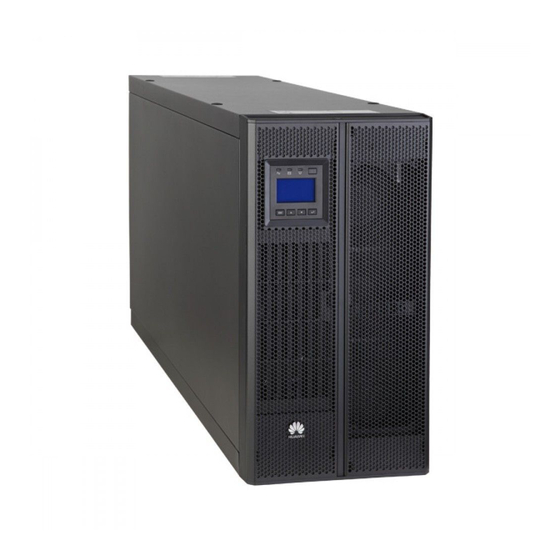
Figure 2-7 UPS conceptual diagram in ECO mode 2.3 Product Introduction 2.3.1 Appearance Figure 2-8 400 kVA/500 kVA UPS (1) Power cabinet (2) Anchor baffle plate (3) MDU (4) Bypass cabinet Issue 06 (2022-01-27) Copyright © Huawei Technologies Co., Ltd. - Page 28 UPS5000-A-(400 kVA-600 kVA) User Manual (60 kVA, PF=0.9) 2 Overview Figure 2-9 600 kVA UPS (1) Power cabinet (2) Anchor baffle plate (3) MDU (4) Bypass cabinet Issue 06 (2022-01-27) Copyright © Huawei Technologies Co., Ltd.
-
Page 29: Structure
Figure 2-10 Product structure (400 kVA UPS) (1) Power units (2) Control unit (3) Mains input switch (4) Output switch (5) Power distribution unit (6) Maintenance bypass switch (PDU) cover (7) Bypass input switch (8) Bypass unit Issue 06 (2022-01-27) Copyright © Huawei Technologies Co., Ltd. - Page 30 Figure 2-11 Product structure (500 kVA UPS) (1) Power units (2) Control unit (3) Mains input switch (4) Output switch (5) PDU cover (6) Maintenance bypass switch (7) Bypass input switch (8) Bypass unit Issue 06 (2022-01-27) Copyright © Huawei Technologies Co., Ltd.
-
Page 31: Control Unit
(ECMs), a dry contact card, and a monitoring interface card. The four cards are hot swappable. One subrack is reserved above the dry contact card. A backfeed protection card or dry contact extended card can be inserted into this subrack. Issue 06 (2022-01-27) Copyright © Huawei Technologies Co., Ltd. -
Page 32: Ecm
The BSC port is used in a dual-bus system to balance output frequencies and phases between UPS systems, ensuring that two buses can switch with each other. BSC cables are hot-swappable. Issue 06 (2022-01-27) Copyright © Huawei Technologies Co., Ltd. -
Page 33: Dry Contact Card
Figure 2-15 Dry contact card Table 2-4 Ports on the dry contact card Silk Screen Description Status Initial Status Port for detecting ● Connected: battery Disconnected battery grounding grounding fault faults Issue 06 (2022-01-27) Copyright © Huawei Technologies Co., Ltd. - Page 34 ● Disconnected: circuit breaker OFF SWITCH Port for signal STATUS_0V ground SWITCH Port for monitoring ● Disconnected: Disconnected STATUS_MT the maintenance circuit breaker ON circuit breaker ● Connected: circuit breaker OFF Issue 06 (2022-01-27) Copyright © Huawei Technologies Co., Ltd.
- Page 35 The dry contact card allows the UPS to detect and manage the switch status of the battery system (including the external battery switch) and implement remote EPO. Specifications ● Hot-swappable ● 0.5 U high Issue 06 (2022-01-27) Copyright © Huawei Technologies Co., Ltd.
-
Page 36: Monitoring Interface Card
Table 2-5 Ports on the monitoring interface card Port Silk Description Screen DO_1 ● DO_1, DO_2, DO_3, and DO_4 indicate alarm outputs. The default values are Critical alarm, Minor alarm, Bypass mode, and Battery mode, respectively. DO_2 Issue 06 (2022-01-27) Copyright © Huawei Technologies Co., Ltd. - Page 37 ● Signal cables must be double-insulated twisted cables. If the cable length is 25–50 m, the cross-sectional area must be 0.5–1.5 mm ● RS485 cables and FE cables must be shielded cables. Figure 2-17 Figure 2-18 are recommended wiring methods for DO ports. Issue 06 (2022-01-27) Copyright © Huawei Technologies Co., Ltd.
- Page 38 UPS5000-A-(400 kVA-600 kVA) User Manual (60 kVA, PF=0.9) 2 Overview Figure 2-17 Wiring method 1 Figure 2-18 Wiring method 2 Figure 2-19 COM1 pins Table 2-6 COM1 pin definition Description RS485– RS485+ 12V_PORT Issue 06 (2022-01-27) Copyright © Huawei Technologies Co., Ltd.
- Page 39 UPS5000-A-(400 kVA-600 kVA) User Manual (60 kVA, PF=0.9) 2 Overview Figure 2-20 COM2 pins Table 2-7 COM2 pin definition Description RS485+ RS485– RS485+ RS485– CANH0 CANL0 Figure 2-21 RS485 pins Issue 06 (2022-01-27) Copyright © Huawei Technologies Co., Ltd.
-
Page 40: Mdu
RS485+. Twist cables to pin 2 and pin 5 into one cable and then connect it to RS485–. 2.6 MDU There are two types of MDUs. Appearance Figure 2-22 MDU (with flat LCD) Issue 06 (2022-01-27) Copyright © Huawei Technologies Co., Ltd. - Page 41 The UPS is running properly or a warning has been generated. The MDU is powered off. NO TE The indicator on the MDU panel is yellow when the bypass supplies power in non-ECO mode. Figure 2-24 MDU ports Issue 06 (2022-01-27) Copyright © Huawei Technologies Co., Ltd.
- Page 42 Figure 2-25 Ports on the old MDU Table 2-11 Port description for the old MDU Port Name Description MUS05A (DB26) Connects to the MDU and monitoring interface card. Issue 06 (2022-01-27) Copyright © Huawei Technologies Co., Ltd.
-
Page 43: Typical Configurations
Application Scenario Single UPS Supplies power to common loads. Parallel system Supplies power to small- and medium-sized equipment rooms or important loads. It features high reliability and strong transient overload resistance capability. Issue 06 (2022-01-27) Copyright © Huawei Technologies Co., Ltd. -
Page 44: Single Ups
LCD or WebUI. 2.7.1 Single UPS The UPS5000-A is a series of transformerless tower-mounted UPSs. This series uses the unit-level design for its power part with an embedded maintenance bypass switch, enabling maintenance with power on. -
Page 45: Dual-Bus System
Converges the energy of 2000) DCV8-BGA001 V8-BGA001 multiple battery strings. Battery Bus Bar Box User ● PDU8000-2000DC Manual V8-BGA001 IP21 Prevents water from component dropping into the cabinet, protecting the cabinet to IP21. Issue 06 (2022-01-27) Copyright © Huawei Technologies Co., Ltd. - Page 46 ● If an IP21 component is configured, top cable routing is not supported. ● The ECM expansion subrack does not support onsite installation. If you require this optional component, specify it when you purchase the device and the component will be preinstalled. Issue 06 (2022-01-27) Copyright © Huawei Technologies Co., Ltd.
-
Page 47: Installation
UPS5000-A-(400 kVA-600 kVA) User Manual (60 kVA, PF=0.9) 3 Installation Installation 3.1 Installation Preparations 3.1.1 Site Planning 3.1.1.1 UPS Dimensions Figure 3-1 Dimensions (400 kVA/500 kVA, unit: mm) Issue 06 (2022-01-27) Copyright © Huawei Technologies Co., Ltd. -
Page 48: Installation Environment
Reserve a clearance of at least 500 mm from the rear of the cabinets for ventilation. If the UPS will be operated from the rear, reserve a clearance of at least 800 mm for operations. Issue 06 (2022-01-27) Copyright © Huawei Technologies Co., Ltd. -
Page 49: Tools And Instruments
Use insulated tools to avoid electric shocks. Table 3-1 lists the tools and instruments required for the installation. Table 3-1 Tools and instruments Tools and Instruments Electric forklift Manual pallet Step ladder Rubber mallet truck Issue 06 (2022-01-27) Copyright © Huawei Technologies Co., Ltd. - Page 50 Multimeter Cable tie Level Insulation tape Cotton cloth Label Electrician's knife Electrostatic Protective gloves Insulated gloves Insulated discharge (ESD) protective shoes gloves Torque Cable cutter Brush Flat-head screwdriver screwdriver (2–5 mm) Issue 06 (2022-01-27) Copyright © Huawei Technologies Co., Ltd.
-
Page 51: Preparing Power Cables
600 kVA Mains Input current (A) input Recommended 2 x (4 x 185) 3 x (4 x 185) 3 x (4 x 240) cross-sectional area (mm Bypass Input current (A) input Issue 06 (2022-01-27) Copyright © Huawei Technologies Co., Ltd. - Page 52 The maximum battery discharge current refers to the current when forty 12 V batteries in standard configuration, that is, two hundred and forty 2 V battery cells (1.67 V/cell), stop discharging. Issue 06 (2022-01-27) Copyright © Huawei Technologies Co., Ltd.
- Page 53 N·m Bypass Crimped DT 18 mm input terminal N·m Battery Crimped DT 18 mm input terminal N·m Output Crimped DT 18 mm terminal N·m Crimped DT 35 mm 47 N·m terminal Issue 06 (2022-01-27) Copyright © Huawei Technologies Co., Ltd.
- Page 54 ● If multiple loads are connected, specifications for branch circuit breakers must not exceed the recommended specifications. ● Select proper circuit breakers to protect loads and cables, and cascade them properly to achieve specific protection. Issue 06 (2022-01-27) Copyright © Huawei Technologies Co., Ltd.
-
Page 55: Unpacking
Step 3 After confirming that the UPS is intact, remove the bolts that secure the UPS to the pallet and remove the UPS from the pallet. Figure 3-4 Removing the pallet from the UPS ----End 3.2 Installing a Single UPS Issue 06 (2022-01-27) Copyright © Huawei Technologies Co., Ltd. -
Page 56: Installing A Ups Cabinet
● A: mounting holes on the channel steel ● B: mounting holes on the floor Figure 3-5 Mounting hole dimensions for the 400 kVA UPS and 500 kVA UPS (unit: mm) Issue 06 (2022-01-27) Copyright © Huawei Technologies Co., Ltd. - Page 57 Step 3 Use a pallet truck to move the cabinet to the installation position. Step 4 Use M12x60 expansion bolts to secure the cabinet to the expansion bolt mounting holes on the floor. Issue 06 (2022-01-27) Copyright © Huawei Technologies Co., Ltd.
- Page 58 3 Installation Figure 3-8 Tightening expansion bolts Step 5 Install the front, rear, left, and right anchor baffle plates. Figure 3-9 Installing the front, rear, left, and right anchor baffle plates ----End Issue 06 (2022-01-27) Copyright © Huawei Technologies Co., Ltd.
-
Page 59: Installation On Channel Steel
● A: mounting holes on the channel steel ● B: mounting holes on the floor Figure 3-10 Mounting hole dimensions for the 400 kVA UPS and 500 kVA UPS (unit: mm) Issue 06 (2022-01-27) Copyright © Huawei Technologies Co., Ltd. -
Page 60: Installing Batteries
● Install the batteries from the lower layer to the upper layer to prevent falling over due to imbalance. Procedure Step 1 Install the battery rack and batteries. For details, see the battery installation guide delivered with batteries. ----End 3.2.3 Installing Optional Components Issue 06 (2022-01-27) Copyright © Huawei Technologies Co., Ltd. -
Page 61: Installing An Ip21 Component
Figure 3-13 Installing an IP21 component ----End 3.2.3.2 Connecting an Ambient T/H Sensor Procedure Step 1 Connect the RJ11 port on the ambient T/H sensor to the COM1 port on the monitoring interface card. Issue 06 (2022-01-27) Copyright © Huawei Technologies Co., Ltd. -
Page 62: Installing A Battery Grounding Failure Detector
NO TE The ambient T/H sensor can be used as a battery temperature sensor. ----End 3.2.3.3 Installing a Battery Grounding Failure Detector Procedure Step 1 Install a battery grounding failure detector. Issue 06 (2022-01-27) Copyright © Huawei Technologies Co., Ltd. -
Page 63: Ups Cable Connection Reference
● Prepare terminals onsite. The length of the copper wire should be the same as that of the part of the terminal that covers the conductor. Procedure Step 1 Route a cable into the cabinet and bind it to a nearby beam. Issue 06 (2022-01-27) Copyright © Huawei Technologies Co., Ltd. -
Page 64: Routing Cables
● Determine the cable cross-sectional area and quantity based on the section "Preparing Power Cables" and site requirements. The figures are for reference only. Issue 06 (2022-01-27) Copyright © Huawei Technologies Co., Ltd. - Page 65 User Manual (60 kVA, PF=0.9) 3 Installation Figure 3-17 PDU for 400 kVA UPS and 500 kVA UPS (1) Mains input (2) Battery input (3) Output terminal (4) Bypass input terminal terminals terminal Issue 06 (2022-01-27) Copyright © Huawei Technologies Co., Ltd.
- Page 66 (3) Output terminal (4) Bypass input terminal terminals terminal Procedure Step 1 Open the front door of the bypass cabinet and remove the front covers of the PDU from the bypass cabinet. Issue 06 (2022-01-27) Copyright © Huawei Technologies Co., Ltd.
- Page 67 Figure 3-20 Removing the top cable covers Step 3 Remove the rear covers from the bypass cabinet. NO TE You are advised to remove the side panels from the bypass cabinet before connecting cables. Issue 06 (2022-01-27) Copyright © Huawei Technologies Co., Ltd.
- Page 68 The protective covers need to be reinstalled after the connecting copper bars are removed. Figure 3-21 Removing the copper bar protective covers at the rear Issue 06 (2022-01-27) Copyright © Huawei Technologies Co., Ltd.
- Page 69 ● Before connecting cables, ensure that all UPS input switches are turned off. Attach warning labels to avoid misoperations on switches. ● Connect input power cables to the UPS and then to customer equipment. Issue 06 (2022-01-27) Copyright © Huawei Technologies Co., Ltd.
- Page 70 UPS5000-A-(400 kVA-600 kVA) User Manual (60 kVA, PF=0.9) 3 Installation Figure 3-23 Grounding Step 6 Connect mains input power cables. Figure 3-24 Connecting mains input power cables Step 7 Connect output power cables. Issue 06 (2022-01-27) Copyright © Huawei Technologies Co., Ltd.
- Page 71 Figure 3-25 Connecting AC output power cables Step 8 Connect bypass input power cables. (Perform this step only when the mains input and bypass input use different power sources.) Issue 06 (2022-01-27) Copyright © Huawei Technologies Co., Ltd.
- Page 72 ● The battery voltage may be fatal. Observe safety precautions when connecting cables. ● Ensure that cables are correctly connected between battery strings and the battery switch, and between the battery switch and the UPS. Avoid reverse connections. Issue 06 (2022-01-27) Copyright © Huawei Technologies Co., Ltd.
- Page 73 20 batteries. Figure 3-28 Neutral wire Step 10 Route signal cables. Bind cables to the nearby cabinet. Figure 3-29 shows a signal cable routed from the top of the cabinet. Issue 06 (2022-01-27) Copyright © Huawei Technologies Co., Ltd.
- Page 74 The number and color of the signal cable shown in the figure are for reference only. ----End Follow-up Procedure After connecting cables, check that a certain clearance is reserved between the internal switch extension pole and power cables to avoid friction. Issue 06 (2022-01-27) Copyright © Huawei Technologies Co., Ltd.
-
Page 75: Bottom Cable Routing
Step 2 Remove the cable covers from the bottom of the cabinet, drill holes in the covers, attach grommet strips to the hole edges to protect cables, and reinstall the cable covers. NO TE The hole size and quantity are for reference only. Issue 06 (2022-01-27) Copyright © Huawei Technologies Co., Ltd. - Page 76 Step 5 Connect a ground cable to the UPS. CA UTION If you do not ground the UPS as required, electromagnetic interference, electric shocks, or fire may occur. Issue 06 (2022-01-27) Copyright © Huawei Technologies Co., Ltd.
- Page 77 ● Connect input power cables to the UPS and then to customer equipment. Figure 3-31 Grounding Step 6 Connect bypass input power cables. (Perform this step only when the mains input and bypass input use different power sources.) Issue 06 (2022-01-27) Copyright © Huawei Technologies Co., Ltd.
- Page 78 Step 7 Connect output power cables. CA UTION After you connect output power cables, if loads are not ready to be powered, insulate the end of the system output power cables. Issue 06 (2022-01-27) Copyright © Huawei Technologies Co., Ltd.
- Page 79 UPS5000-A-(400 kVA-600 kVA) User Manual (60 kVA, PF=0.9) 3 Installation Figure 3-33 Connecting output power cables Step 8 Connect mains input power cables. Issue 06 (2022-01-27) Copyright © Huawei Technologies Co., Ltd.
- Page 80 ● The battery voltage may be fatal. Observe safety precautions when connecting cables. ● Ensure that cables are correctly connected between battery strings and the battery switch, and between the battery switch and the UPS. Avoid reverse connections. Issue 06 (2022-01-27) Copyright © Huawei Technologies Co., Ltd.
- Page 81 Take a battery string consisting of 40 batteries for example. The battery neutral wire is routed from the middle of positive and negative battery strings, each consisting of 20 batteries. Figure 3-36 Neutral wire Issue 06 (2022-01-27) Copyright © Huawei Technologies Co., Ltd.
- Page 82 The number and color of the signal cable shown in the figure are for reference only. ----End Follow-up Procedure After connecting cables, check that a certain clearance is reserved between the internal switch extension pole and power cables to avoid friction. Issue 06 (2022-01-27) Copyright © Huawei Technologies Co., Ltd.
-
Page 83: Connecting A Remote Epo Switch
● When the NO status is required, ensure that the jumper is connected between EPO_NC and EPO_12V. In this way, the EPO is triggered when you turn on the EPO switch. Issue 06 (2022-01-27) Copyright © Huawei Technologies Co., Ltd. -
Page 84: Installing A Parallel System
The typical scenario is used as an example. Figure 3-40 Conceptual diagram of a 1+1 parallel system NO TICE Connect power cables according to the silk screen on the terminals. Issue 06 (2022-01-27) Copyright © Huawei Technologies Co., Ltd. - Page 85 A dual-bus system is used as an example. NO TICE The length and specifications of power cables on each UPS should be the same to achieve current equalization in bypass mode. Issue 06 (2022-01-27) Copyright © Huawei Technologies Co., Ltd.
- Page 86 UPS5000-A-(400 kVA-600 kVA) User Manual (60 kVA, PF=0.9) 3 Installation Figure 3-42 Conceptual diagram of a dual-bus parallel system Issue 06 (2022-01-27) Copyright © Huawei Technologies Co., Ltd.
-
Page 87: Connecting Signal Cables
Connecting Signal Cables to a Parallel System Connect the parallel ports on the UPSs over parallel cables to create a loop. ● Figure 3-44 Figure 3-45 show the wiring principle for an N+X parallel system. Issue 06 (2022-01-27) Copyright © Huawei Technologies Co., Ltd. - Page 88 Figure 3-45 Signal cable connections of an N+X parallel system ● Connect BSC cables between the master and slave systems of the dual-bus system. Figure 3-46 shows how to connect cables for a dual-bus system. Issue 06 (2022-01-27) Copyright © Huawei Technologies Co., Ltd.
-
Page 89: Verifying The Installation And Filling The Sealing Putty
3.4 Verifying the Installation and Filling the Sealing Putty NO TICE You need to carefully check items 08 and 09 listed in the following table. Otherwise, the UPS may be damaged. Issue 06 (2022-01-27) Copyright © Huawei Technologies Co., Ltd. - Page 90 4. There is no foreign matter on the bottom plate of the cabinet. 5. There is no foreign matter behind the cabinet. Issue 06 (2022-01-27) Copyright © Huawei Technologies Co., Ltd.
- Page 91 Figure 3-47 Positions to be checked for foreign matters (1) Switches (2) Mains input wiring copper (3) Battery input wiring copper bars (4) Output wiring copper bar (5) Bypass input wiring copper (6) Cabinet rear Issue 06 (2022-01-27) Copyright © Huawei Technologies Co., Ltd.
- Page 92 Figure 3-48 Filling sealing putty (1) Paper protective film (2) Transparent film (3) Sealing putty (with the transparent film facing upward) Figure 3-49 Dust cover (1) Do not remove the dust cover before power-on. Issue 06 (2022-01-27) Copyright © Huawei Technologies Co., Ltd.
-
Page 93: Operations
Step 2 Turn on the UPS bypass input switch, mains input switch, and output switch. After the UPS is powered on, initialization begins. The MDU displays the initialization progress bar. ----End 4.1.2 Initial Startup Issue 06 (2022-01-27) Copyright © Huawei Technologies Co., Ltd. -
Page 94: Obtaining Startup Password
The system displays the Bypass mode and No battery alarms, which do not need to be handled. ----End 4.1.2.2 Settings Wizard Procedure Step 1 Set the language, time and date, network parameters, system parameters, and battery parameters on the Settings Wizard screen. Issue 06 (2022-01-27) Copyright © Huawei Technologies Co., Ltd. - Page 95 ● After you set network parameters, connect the UPS to the network over a network cable, which allows you to remotely manage the UPS. If you do not need remote management, retain the default network parameter settings. Issue 06 (2022-01-27) Copyright © Huawei Technologies Co., Ltd.
-
Page 96: Starting The Inverter
Step 3 In the displayed dialog box, tap Yes to start the inverter. ----End Starting the UPS on the WebUI Step 1 Open a browser (for example: Internet Explorer 11) and choose Tools > Internet Options. Issue 06 (2022-01-27) Copyright © Huawei Technologies Co., Ltd. - Page 97 Step 4 Enter the correct user name and password and click Login. Step 5 On the WebUI, choose Monitoring > Control, click Inv. ON, and confirm the operation to start the inverter. Figure 4-3 Starting the inverter Issue 06 (2022-01-27) Copyright © Huawei Technologies Co., Ltd.
-
Page 98: Powering On Loads
A BCB box is installed. Procedure Step 1 On the System Info > Settings > Dry Contact Set screen, set MUE05A connection to Enable, and set BCB connection [OL] and Battery breaker [STA] to Enable. Issue 06 (2022-01-27) Copyright © Huawei Technologies Co., Ltd. -
Page 99: Shutting Down And Powering Off The Ups
On the LCD On the main screen, tap Common Functions. Tap Inv. OFF. NO TE To shut down the inverter on the Maintenance screen, tap System Info > Maintenance. Figure 4-5 Normal bypass Issue 06 (2022-01-27) Copyright © Huawei Technologies Co., Ltd. -
Page 100: Cold-Starting The Ups Using Batteries
Step 2 Turn off the mains and bypass upstream input switches, and turn on the battery circuit breaker. If there are multiple battery strings, turn on the circuit breaker for each battery string and then the general circuit breaker between the battery strings and the UPS. Issue 06 (2022-01-27) Copyright © Huawei Technologies Co., Ltd. -
Page 101: Transferring To Bypass Mode
ECO mode when the bypass input is unstable or is sensitive to load changes. ● ECO mode is not recommended when the load is less than 10%. ● Before setting ECO mode, ensure that the bypass is working properly. Issue 06 (2022-01-27) Copyright © Huawei Technologies Co., Ltd. -
Page 102: Battery Test
If the bypass is abnormal, the inverter supplies power immediately. If the inverter is not started, the UPS may be disconnected. Figure 4-8 System status in ECO mode ----End 4.6 Battery Test Issue 06 (2022-01-27) Copyright © Huawei Technologies Co., Ltd. -
Page 103: Forced Equalized Charging Test
● The forced equalized charging test duration reaches the forced equalized charging protection time (12–24 h, 18 h by default). ● The UPS generates a battery overtemperature, overvoltage, or overcurrent alarm. ● A fault alarm is generated. ----End Issue 06 (2022-01-27) Copyright © Huawei Technologies Co., Ltd. -
Page 104: Shallow Discharge Test
Step 1 On the home screen of the LCD, choose System Info > Maintenance > Battery Maint. Step 2 Tap Start next to Shallow Dis. Test to start a shallow discharge test. Figure 4-10 Starting a shallow discharge test Issue 06 (2022-01-27) Copyright © Huawei Technologies Co., Ltd. -
Page 105: Capacity Test
Step 1 On the home screen of the LCD, choose System Info > Maintenance > Battery Maint. Step 2 Tap Start on the right of Capacity Test to start a capacity test. Figure 4-11 Starting a capacity test Issue 06 (2022-01-27) Copyright © Huawei Technologies Co., Ltd. -
Page 106: Test Data Download
Figure 4-13 Logs Choose logs that have been queried from the Log drop-down list box, and click Export. 4.7 Transferring to Maintenance Bypass Mode Prerequisites The maintenance bypass unit has been installed. Issue 06 (2022-01-27) Copyright © Huawei Technologies Co., Ltd. -
Page 107: Transferring From Maintenance Bypass Mode To Inverter Mode
Procedure Step 1 Turn the maintenance bypass switch from ON to OFF. NO TE The Maint. breaker closed alarm disappears from the MDU. Step 2 Start the inverter. ----End Issue 06 (2022-01-27) Copyright © Huawei Technologies Co., Ltd. -
Page 108: Performing Epo
Clear Faults. The EPO alarm is cleared. Step 3 View active alarms and check that the EPO alarm is cleared. If the system bypass input is normal, the UPS transfers to bypass mode. Issue 06 (2022-01-27) Copyright © Huawei Technologies Co., Ltd. -
Page 109: Exporting Data
Click Export Historical Data and save the displayed webpage. Old Web Choose Query > Historical Alarms, set Severity, Generated, and Cleared, and click Query to query the historical alarm information. Figure 4-16 Querying historical alarms Issue 06 (2022-01-27) Copyright © Huawei Technologies Co., Ltd. - Page 110 NO TE You do not need to query logs. You only need to choose Query > Logs, click Export, and save the log file. Click Export and save the displayed webpage. Issue 06 (2022-01-27) Copyright © Huawei Technologies Co., Ltd.
-
Page 111: Routine Maintenance
● Only maintenance engineers are allowed to maintain the power unit and bypass unit. ● Maintain UPSs regularly based on the following requirements. Otherwise, the UPSs may fail to operate properly and the service life may be shortened. Issue 06 (2022-01-27) Copyright © Huawei Technologies Co., Ltd. -
Page 112: Monthly Maintenance
Wipe the cabinet surface using Remove the dust, especially a white paper and the paper from the air filter on the front does not turn black. door, or replace the air filter. Issue 06 (2022-01-27) Copyright © Huawei Technologies Co., Ltd. -
Page 113: Annual Maintenance
The circuit breakers and ● Replace the circuit of cables and circuit cables meet load breakers. breakers requirements. ● Replace the cables. The actual cable through-current capacity is greater than the circuit breaker specifications. Issue 06 (2022-01-27) Copyright © Huawei Technologies Co., Ltd. -
Page 114: Battery Maintenance
5.2.2 Monthly Maintenance Table 5-4 Monthly maintenance Item Expected Result Troubleshooting Battery No battery management Identify the cause of an alarm management alarm is generated. based on the alarm alarm information. Issue 06 (2022-01-27) Copyright © Huawei Technologies Co., Ltd. - Page 115 2. Check whether the equalized charging voltage and float charging voltage are correctly set for the UPS. 3. If the fault persists, contact technical support. Issue 06 (2022-01-27) Copyright © Huawei Technologies Co., Ltd.
-
Page 116: Quarterly Maintenance
UPS is backed up to verify locate the fault (for that the batteries can abnormal alarms, see discharge normally. the alarm list). 2. If the fault persists, contact technical support. Issue 06 (2022-01-27) Copyright © Huawei Technologies Co., Ltd. -
Page 117: Annual Maintenance
(A torque wrench is used for checking the torque. After checking that the battery screws meet the requirements, mark the screws for later check.) Issue 06 (2022-01-27) Copyright © Huawei Technologies Co., Ltd. -
Page 118: Troubleshooting
EOD voltage and 11.3 V/cell. For details about how to rectify common faults, see Table 6-1. If any unmentioned faults occur, see the alarm list or contact technical support. Issue 06 (2022-01-27) Copyright © Huawei Technologies Co., Ltd. - Page 119 The buzzer buzzes, The bypass thyristor Replace the bypass bypass is and the fault is damaged. unit. abnormal indicator is on. The bypass unit Reduce the load, or experiences improve ventilation. overtemperature. Issue 06 (2022-01-27) Copyright © Huawei Technologies Co., Ltd.
- Page 120 UPS5000-A-(400 kVA-600 kVA) User Manual (60 kVA, PF=0.9) 6 Troubleshooting NO TE For details about component replacement and maintenance mentioned in Troubleshooting and Alarm List, consult maintenance engineers. Issue 06 (2022-01-27) Copyright © Huawei Technologies Co., Ltd.
-
Page 121: Technical Specifications
A-500K-FTS AC/800 A/3P 1000 A/3P AC/800 A/3P AC/800 A/3P UPS5000- 1000 V AC/ 1000 V AC/ 1000 V AC/ 1000 V AC/ A-600K-FTS 1000 A/3P 1250 A/3P 1000 A/3P 1000 A/3P Issue 06 (2022-01-27) Copyright © Huawei Technologies Co., Ltd. - Page 122 EN 61000-4-6 EN/IEC 62040-2 IEC 61000-4-6 Radiated susceptibility EN 61000-4-3 EN/IEC 62040-2 IEC 61000-4-3 Electrical fast transient EN/IEC 62040-2 IEC 61000-4-4 Surge EN/IEC 62040-2 IEC 61000-4-5 Power magnetic susceptibility IEC 61000-4-8 Issue 06 (2022-01-27) Copyright © Huawei Technologies Co., Ltd.
- Page 123 ● THDi < 5% (full non-linear load) Table 7-6 Bypass input specifications Item Specifications Input Three-phase, four-wire, and PE system Rated input 380 V AC/400 V AC/415 V AC (line voltage) voltage Rated 50/60 Hz frequency Issue 06 (2022-01-27) Copyright © Huawei Technologies Co., Ltd.
- Page 124 Output Three-phase four-wire, and PE system Voltage 380 V AC/400 V AC/415 V AC±1% (line voltage) THDv ● THDv ≤ 1% (100% linear load) ● THDv ≤ 4% (100% non-linear load) Issue 06 (2022-01-27) Copyright © Huawei Technologies Co., Ltd.
- Page 125 Specifications Voltage Input voltage, bypass voltage, output voltage, bus voltage, and display charge voltage: 1% precision Frequency Input, bypass, and output frequency: 1% display precision ECO in a Supported parallel system Issue 06 (2022-01-27) Copyright © Huawei Technologies Co., Ltd.
-
Page 126: A (Optional) Tn-C System Application
● The following cable connection is for reference only. Figure A-1 Short-circuiting the input N and PE Table A-1 Recommended cross-sectional areas for cables Model Current (A) Recommended Cross- Sectional Area (mm 400 kVA Issue 06 (2022-01-27) Copyright © Huawei Technologies Co., Ltd. - Page 127 UPS5000-A-(400 kVA-600 kVA) User Manual (60 kVA, PF=0.9) A (Optional) TN-C System Application Model Current (A) Recommended Cross- Sectional Area (mm 500 kVA 600 kVA Issue 06 (2022-01-27) Copyright © Huawei Technologies Co., Ltd.
-
Page 128: B User Interface
UPS5000-A-(400 kVA-600 kVA) User Manual (60 kVA, PF=0.9) B User Interface User Interface NO TE For details, see the UPS5000-A Monitoring Unit User Manual . Issue 06 (2022-01-27) Copyright © Huawei Technologies Co., Ltd. -
Page 129: C Alarm List
UPS5000-A-(400 kVA-600 kVA) User Manual (60 kVA, PF=0.9) C Alarm List Alarm List NO TE For details about alarms, see the UPS5000 & SmartLi Alarm Reference . Issue 06 (2022-01-27) Copyright © Huawei Technologies Co., Ltd. -
Page 130: D Acronyms And Abbreviations
D Acronyms and Abbreviations Acronyms and Abbreviations AC transfer switch American Wire Gauge bus synchronization controller BCB-BOX battery circuit breaker box BBB-BOX battery bus bar box Conformite Europeenne digital signal processing economic control operation Issue 06 (2022-01-27) Copyright © Huawei Technologies Co., Ltd. - Page 131 International Electrotechnical Commission liquid crystal display monitor display unit personal computer protective earthing power distribution unit RS485 Recommended Standard static transfer switch SNMP Simple Network Management Protocol Issue 06 (2022-01-27) Copyright © Huawei Technologies Co., Ltd.
- Page 132 User Manual (60 kVA, PF=0.9) D Acronyms and Abbreviations THDi total harmonic distortion of input current THDv total harmonic distortion of output voltage uninterruptible power system Universal Serial Bus VRLA valve-regulated lead acid Issue 06 (2022-01-27) Copyright © Huawei Technologies Co., Ltd.
Need help?
Do you have a question about the UPS5000-A and is the answer not in the manual?
Questions and answers