
Related Manuals for Huawei UPS5000-A-30 kVA


Summary of Contents for Huawei UPS5000-A-30 kVA
- Page 1 UPS5000-A-30 kVA & 40 kVA & 80 kVA User Manual Issue Date 2018-12-10 HUAWEI TECHNOLOGIES CO., LTD.
- Page 2 Notice The purchased products, services and features are stipulated by the contract made between Huawei and the customer. All or part of the products, services and features described in this document may not be within the purchase scope or the usage scope. Unless otherwise specified in the contract, all statements, information, and recommendations in this document are provided "AS IS"...
-
Page 3: About This Document
About This Document About This Document Purpose This document describes the high-frequency tower-mounted UPS5000-A-30 kVA & 40 kVA & 80 kVA in terms of features, appearance, structure, working principle, technical specifications, installation, operation, and maintenance. UPS is short for uninterruptible power system. - Page 4 UPS5000-A-30 kVA & 40 kVA & 80 kVA User Manual About This Document Symbol Description Indicates a potentially hazardous situation which, if not avoided, could result in equipment damage, data loss, performance deterioration, or unanticipated results. NOTICE is used to address practices not related to personal injury.
- Page 5 UPS5000-A-30 kVA & 40 kVA & 80 kVA User Manual About This Document Updated the section 6 "Routine Maintenance". Added the specifications of the internal circuit breaker in the section 8 "Technical Specifications". Issue 06 (2015-06-26) This issue is the sixth official release, which incorporates the following changes: Updated the Monitoring screen image.
-
Page 6: Table Of Contents
UPS5000-A-30 kVA & 40 kVA & 80 kVA User Manual Contents Contents About This Document ........................ii 1 Safety Precautions ......................... 1 1.1 General Safety ................................1 1.2 Electrical Safety ................................3 1.3 Operating Environment..............................6 1.4 Battery Safety ................................6 1.5 Mechanical Safety ................................ - Page 7 UPS5000-A-30 kVA & 40 kVA & 80 kVA User Manual Contents 3.1.1 Site ................................... 32 3.1.2 Tools and Instruments .............................. 35 3.1.3 Power Cables ................................37 3.1.4 Unpacking and Checking ............................42 3.1.4.1 30 kVA/40 kVA UPS ............................. 43 3.1.4.2 80 kVA UPS ................................44 3.2 Installing a Single UPS ...............................
- Page 8 UPS5000-A-30 kVA & 40 kVA & 80 kVA User Manual Contents 4.3.3.1 Historical Alarms Page ............................133 4.3.3.2 Logs Page ................................133 4.3.4 Config. Page ................................134 4.3.4.1 User Management ............................... 134 4.3.4.2 Site Config................................134 4.3.4.3 RCCMD ................................136 4.3.4.4 Managing the UPS by Using the NMS Complying with RFC1628 Standard .............
- Page 9 UPS5000-A-30 kVA & 40 kVA & 80 kVA User Manual Contents 8.3 Environmental Specifications ........................... 178 8.4 Safety Regulations and EMC ............................ 179 8.5 Mains Input Electrical Specifications ........................179 8.6 Bypass Input Electrical Specifications ........................180 8.7 Battery Specifications ............................... 180 8.8 Output Electrical Specifications ..........................
-
Page 10: Safety Precautions
Follow the precautions and special safety instructions provided by Huawei when operating Huawei products. Huawei will not be liable for any consequences that are caused due to violations regarding general safety regulations and equipment design, production, and usage safety standards. - Page 11 Personal Requirements Only Huawei engineers or engineers certified by Huawei are allowed to perform UPS commissioning and maintenance. Otherwise, human injury or equipment damage may occur, and any resulting UPS faults will be beyond warranty scope.
-
Page 12: Electrical Safety
UPS5000-A-30 kVA & 40 kVA & 80 kVA User Manual 1 Safety Precautions In the case of fire, leave the building or the equipment room immediately, and turn on the fire alarm bell or make an emergency call. Never enter the building on fire in any case. - Page 13 UPS5000-A-30 kVA & 40 kVA & 80 kVA User Manual 1 Safety Precautions When operating the AC power supply facility, ensure compliance with local laws and regulations. Before connecting cables to the UPS, ensure that the input power and mains power distribution switches and output power distribution switch are turned off.
- Page 14 UPS5000-A-30 kVA & 40 kVA & 80 kVA User Manual 1 Safety Precautions static bypass circuits. If device installation and maintenance personnel do not need to use backfeed protection, paste labels on the external bypass input circuit breakers informing that the circuit is connected to the UPS.
-
Page 15: Operating Environment
UPS5000-A-30 kVA & 40 kVA & 80 kVA User Manual 1 Safety Precautions 1.3 Operating Environment The UPS is used for commercial and industrial purposes only. It cannot be used as a power supply for life support devices. The TIER4 or TIER3 power supply architecture specified in TIA942, that is, dual power... - Page 16 1 Safety Precautions To ensure battery safety and efficient battery management, use the batteries delivered with the UPS. Huawei shall not be responsible for battery damage caused by using non-Huawei batteries for Huawei UPSs. Ensure lead-acid battery handling is in accordance with local regulations.
-
Page 17: Mechanical Safety
UPS5000-A-30 kVA & 40 kVA & 80 kVA User Manual 1 Safety Precautions Do not use unsealed lead-acid batteries. Lead-acid batteries emit flammable gas. Therefore, place and secure lead-acid batteries horizontally to prevent fire or corrosion. Store lead-acid batteries in a place with good ventilation, and take fire safety precautions. -
Page 18: Laying Out Cables
UPS5000-A-30 kVA & 40 kVA & 80 kVA User Manual 1 Safety Precautions Moving Heavy Objects Perform operations in accordance with all instructional symbols on the device. Take caution to avoid injury when moving heavy objects. When moving or lifting a device, hold the handle or bottom of the device. -
Page 19: Information About Foreign Objects Near Ups Equipment Installation
Huawei UPS uses the highest safety standard in equipment design to ensure that live parts are not in contact with the exterior and that no foreign object will enter the equipment during operation. - Page 20 UPS5000-A-30 kVA & 40 kVA & 80 kVA User Manual 1 Safety Precautions manager to ensure that no foreign object enters the UPS modules/units or relevant auxiliary equipment/components. Issue 11 (2018-12-10) Copyright © Huawei Technologies Co., Ltd.
-
Page 21: Overview
UPS5000-A-30 kVA & 40 kVA & 80 kVA User Manual 2 Overview Overview 2.1 Model Description This document describes the following UPS models: UPS5000-A-30KTTL UPS5000-A-40KTTL UPS5000-A-80KTTL Figure 2-1 Model number 2.2 Working Principles indicates an input mode. -
Page 22: Working Modes
UPS5000-A-30 kVA & 40 kVA & 80 kVA User Manual 2 Overview Figure 2-2 UPS conceptual diagram 2.2.2 Working Modes 2.2.2.1 Normal Mode When the UPS works in normal mode, the rectifier converts the AC input voltage into the DC voltage, which is then raised to the bus voltage by the power factor correction (PFC) circuit. -
Page 23: Bypass Mode
UPS5000-A-30 kVA & 40 kVA & 80 kVA User Manual 2 Overview 2.2.2.2 Bypass Mode If the inverter does not start or is manually shut down after the UPS is powered on, the bypass supplies power to loads. The UPS automatically transfers from normal mode to bypass mode if it detects power unit overtemperature, overload, or other faults that may cause the inverter to shut down. -
Page 24: Maintenance Bypass Mode
UPS5000-A-30 kVA & 40 kVA & 80 kVA User Manual 2 Overview Figure 2-5 UPS conceptual diagram in battery mode 2.2.2.4 Maintenance Bypass Mode The current flows through the maintenance bypass, instead of the power unit or bypass unit. UPS maintenance can be performed in this mode. - Page 25 UPS5000-A-30 kVA & 40 kVA & 80 kVA User Manual 2 Overview voltage range, the UPS transfers from bypass mode to normal mode. In bypass mode or normal mode, the rectifier keeps working and charges batteries using a charger. The ECO mode delivers a higher efficiency.
-
Page 26: Product Description
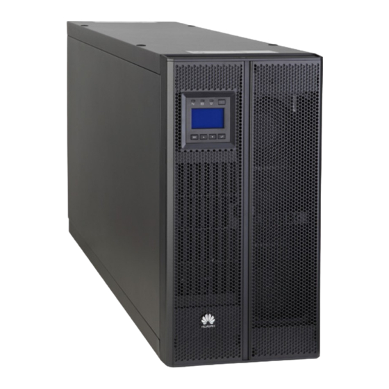
UPS5000-A-30 kVA & 40 kVA & 80 kVA User Manual 2 Overview 2.3 Product Description 2.3.1 Appearance Figure 2-8 UPS5000-A-30 kVA/40 kVA (1) Monitor display unit (MDU) (2) Front panel (3) Support base (4) Chassis Issue 11 (2018-12-10) Copyright © Huawei Technologies Co., Ltd. -
Page 27: Product Structure
UPS5000-A-30 kVA & 40 kVA & 80 kVA User Manual 2 Overview Figure 2-9 UPS5000-A-80 kVA (1) Front panel 1 (2) MDU (3) Front panel 2 (4) Leveling foot (5) Castor (6) Chassis 2.3.2 Product Structure 2.3.2.1 30 kVA/40 kVA UPS... - Page 28 (5) MDU reset (6) Dual in-line package (7) MDU port (8) Cold-start button button (DIP) switch Figure 2-11 UPS5000-A-30 kVA/40 kVA product structure (rear view and enlarged view of certain parts) (1) Ventilation (2) Dry contacts (3) Battery (4) Ambient temperature...
- Page 29 UPS5000-A-30 kVA & 40 kVA & 80 kVA User Manual 2 Overview (5) FE port (upper) (6) BSC port (7) Parallel ports (8) Slot for dry contact and RS485 port card (optional) (lower) (9) UPS mains (10) UPS bypass (11) Battery...
- Page 30 UPS5000-A-30 kVA & 40 kVA & 80 kVA User Manual 2 Overview DIP1 DIP2 DIP3 Function Remarks Swit Operation Statu Settings > Restores After clearing system factory parameters, battery Restore defaults. parameters, monitoring Default parameters, and logs Settings (operation logs, upgrade...
-
Page 31: 80Kva Ups
UPS5000-A-30 kVA & 40 kVA & 80 kVA User Manual 2 Overview 2.3.2.2 80kVA UPS Figure 2-12 UPS5000-A-80 kVA product structure (front view) (3) Bypass unit ready (1) Bypass unit indicators (2) MDU port switch (4) MDU reset button (5) DIP switch... -
Page 32: Control Port
(7) Slot for dry contact card (8) PDU port (optional) UPS5000-A-80 kVA functional components have the same functions as UPS5000-A-30 kVA/40 kVA functional components. For details, see section 2.3.2.1 30 kVA/40 kVA UPS. Connect the BMU by using a 04080298 transfer cable, which is delivered with the BMU. - Page 33 UPS5000-A-30 kVA & 40 kVA & 80 kVA User Manual 2 Overview Silk Screen Description PARALLEL The PARALLEL port transmits parallel signals. To connect multiple UPSs in parallel, use parallel cables to connect the parallel ports on the UPSs. N UPSs require N parallel cables so that two parallel cables are connected to each UPS, which improves parallel connection reliability.
- Page 34 UPS5000-A-30 kVA & 40 kVA & 80 kVA User Manual 2 Overview Silk Screen Description Status BCB_STA Monitors the battery circuit Status: breaker. Closed: battery circuit breaker ON Open: battery circuit breaker OFF The initial status is Open.
- Page 35 UPS5000-A-30 kVA & 40 kVA & 80 kVA User Manual 2 Overview Others Table 2-4 describes other control signal ports. Table 2-4 Signal ports Port Silk Screen Description Battery B_TEMP Connects to the indoor battery temperature sensor. temperature sensor port...
-
Page 36: Typical Configurations
UPS5000-A-30 kVA & 40 kVA & 80 kVA User Manual 2 Overview Figure 2-15 RS485 pins Table 2-6 RS485 pin definition Description RS485_T+ RS485_T- RS485_R+ RS485_R- If cables are prepared onsite, follow the three methods below: Connect pin 1 and pin 2. Pin 1 connects to RS485+ and pin 2 connects to RS485–. -
Page 37: Single Ups
UPS5000-A-30 kVA & 40 kVA & 80 kVA User Manual 2 Overview Configuration Application Scenario Single UPS Supplies power to common loads. Parallel system Supplies power to important loads in small- and medium-sized data centers. It features high availability and strong transient overload capability. -
Page 38: Dual-Bus System
UPS5000-A-30 kVA & 40 kVA & 80 kVA User Manual 2 Overview Figure 2-16 Conceptual diagram of an N+X parallel system 2.4.3 Dual-Bus System A dual-bus system consists of two independent UPS systems. Each of these UPS systems in turn consists of one or more UPSs connected in parallel. Of the two UPS systems, one is a master system, and the other is a slave system. -
Page 39: Optional Components
UPS5000-A-30 kVA & 40 kVA & 80 kVA User Manual 2 Overview Figure 2-17 Conceptual diagram of a dual-bus system 2.5 Optional Components The UPS5000-A provides a variety of optional components to address various customer requirements. Table 2-8 Optional components... - Page 40 UPS5000-A-30 kVA & 40 kVA & 80 kVA User Manual 2 Overview Component Model Function Reference Document Battery bus bar PDU8000-0630D Converges the PDU8000-(0630, (BBB) box CV8-BGA001 energy of multiple 1250, 2000) battery strings. DCV8-BGA001 BBB PDU8000-1250D Box User Manual CV8-BGA001 ...
-
Page 41: Installation
UPS5000-A-30 kVA & 40 kVA & 80 kVA User Manual 3 Installation Installation 3.1 Installation Preparations 3.1.1 Site Dimensions Figure 3-1 UPS5000-A-30 kVA/40 kVA installation dimensions (unit: mm) Issue 11 (2018-12-10) Copyright © Huawei Technologies Co., Ltd. - Page 42 UPS5000-A-30 kVA & 40 kVA & 80 kVA User Manual 3 Installation Issue 11 (2018-12-10) Copyright © Huawei Technologies Co., Ltd.
- Page 43 UPS5000-A-30 kVA & 40 kVA & 80 kVA User Manual 3 Installation Figure 3-2 UPS5000-A-80 kVA installation dimensions (unit: mm) Installation Environment Do not install the UPS in high temperature, low temperature, and damp areas. For details about environmental specifications.
-
Page 44: Tools And Instruments
Keep a clearance of at least 300 mm at the rear of the cabinet. If you need to perform operations at the rear of the cabinet, keep a clearance of at least 800 mm. Figure 3-3 takes the UPS5000-A-30 kVA/40 kVA as an example to show the installation clearance. Figure 3-3 Installation clearances (unit: mm) 3.1.2 Tools and Instruments... - Page 45 UPS5000-A-30 kVA & 40 kVA & 80 kVA User Manual 3 Installation Tools and Meters Hammer drill and Hand-held electric Alloy hole saw Heat gun drill bit Φ16 drill Diagonal pliers Crimping tools Wire stripper Electric hydraulic pliers Clamp meter...
-
Page 46: Power Cables
UPS5000-A-30 kVA & 40 kVA & 80 kVA User Manual 3 Installation Tools and Meters Insulated torque Insulated adjustable Phillips screwdriver Heat shrink tubing wrench wrench (M3/M4/M5/M6/M (M6/M8/M12/M16) Table 3-1 lists only the common tools for installation and cable connection. For more dedicated tools required, see the corresponding component manuals. - Page 47 UPS5000-A-30 kVA & 40 kVA & 80 kVA User Manual 3 Installation Item 30 kVA 40 kVA 80 kVA cross-sectional area (mm Output Output current (A) Recommended 4 x 10 4 x 16 4 x 35 cross-sectional area (mm N (Increase...
- Page 48 UPS5000-A-30 kVA & 40 kVA & 80 kVA User Manual 3 Installation The currents listed in Table 3-2 are measured at a rated voltage of 380 V; if the rated voltage is 400 V, multiply the currents by 0.95; if the rated voltage is 415 V, multiply the currents by 0.92.
- Page 49 UPS5000-A-30 kVA & 40 kVA & 80 kVA User Manual 3 Installation Figure 3-4 OT terminal for the UPS5000-A Table 3-4 OT terminal specifications for the UPS5000-A Nominal Dimensions (mm) conductor terminal cross-secti hole onal area diameter d2 (mm) 6.4± 0.2 12.0±...
- Page 50 UPS5000-A-30 kVA & 40 kVA & 80 kVA User Manual 3 Installation Table 3-5 DT terminal specifications for the UPS5000-A Nomin Bolt ΦH d(mm) D(mm) W(mm) L(mm) diamet (mm) Nomin Deviati Nomin Deviati Refere Nomin Deviat- conduc (mm) value value...
-
Page 51: Unpacking And Checking
UPS5000-A-30 kVA & 40 kVA & 80 kVA User Manual 3 Installation Component Specifications Manufacturer Capacity 40 kVA Mains input T1N160 TMD R100 FFC 3P circuit breaker Bypass input T1N160 TMD R100 FFC 3P circuit breaker 80 kVA Mains input... -
Page 52: Kva/40 Kva Ups
UPS5000-A-30 kVA & 40 kVA & 80 kVA User Manual 3 Installation Only trained personnel are allowed to move the UPS. Use a pallet truck to transport the UPS box secured to a wooden support to the installation position. -
Page 53: Kva Ups
Check that the fittings comply with the packing list. If some fittings are missing or do not comply with the packing list, record the information and contact your local Huawei office immediately. Step 7 Place the UPS in the installation position. - Page 54 UPS5000-A-30 kVA & 40 kVA & 80 kVA User Manual 3 Installation Figure 3-8 Removing binding tape Step 4 Remove the packing materials and foam, as shown in Figure 3-9. Issue 11 (2018-12-10) Copyright © Huawei Technologies Co., Ltd.
- Page 55 Check that the fittings comply with the packing list. If some fittings are missing or do not comply with the packing list, record the information and contact your local Huawei office immediately. Step 7 Remove the UPS front panel, as shown in Figure 3-10.
- Page 56 UPS5000-A-30 kVA & 40 kVA & 80 kVA User Manual 3 Installation Figure 3-10 Removing UPS front panels Press the button on both sides of UPS front panel 1. Remove UPS front panel 1. Remove the screws of UPS front panel 2.
-
Page 57: Installing A Single Ups
UPS5000-A-30 kVA & 40 kVA & 80 kVA User Manual 3 Installation Figure 3-11 Removing the L-shaped bracket Store the removed L-shaped bracket, which will be used to secure the UPS. Step 9 Push the cabinet along the sliding plate to the installation position. - Page 58 UPS5000-A-30 kVA & 40 kVA & 80 kVA User Manual 3 Installation Figure 3-12 Assembling support bases Step 2 Pull the back-end handle out of the UPS, as shown in Figure 3-13. Figure 3-13 Pulling the back-end handle Loosen the back-end handle screws anticlockwise.
- Page 59 UPS5000-A-30 kVA & 40 kVA & 80 kVA User Manual 3 Installation Figure 3-14 Placing the UPS on support bases (unit: mm) Step 4 Push the back-end handle into the groove, as shown in Figure 3-15. For details, see the instructions on the chassis.
- Page 60 UPS5000-A-30 kVA & 40 kVA & 80 kVA User Manual 3 Installation Tighten the screws clockwise to secure the handle. Step 5 Install the front panel, as shown in Figure 3-16. Figure 3-16 Installing the front panel Insert the bottom half of the panel into the UPS.
- Page 61 UPS5000-A-30 kVA & 40 kVA & 80 kVA User Manual 3 Installation ----End Rack-mounting the UPS Step 1 Remove the left and right side panels, handles, and MDU from the UPS chassis, as shown in Figure 3-18. Before you remove the MDU, remove the cables that are connected to the chassis.
- Page 62 UPS5000-A-30 kVA & 40 kVA & 80 kVA User Manual 3 Installation Figure 3-19 Removing the power unit and bypass unit Step 3 Install guide rails (2 U) on the cabinet. Align the lower edge of a guide rail with the lower edge of a U scale, and then engage...
- Page 63 UPS5000-A-30 kVA & 40 kVA & 80 kVA User Manual 3 Installation Figure 3-20 Engaging the mounting brackets (rear view) (1) Scale (2) Mounting bracket (3) Lower edge of a U scale Ensure that the lower edge of the guide rail is aligned with the lower edge of a U scale.
- Page 64 UPS5000-A-30 kVA & 40 kVA & 80 kVA User Manual 3 Installation Figure 3-22 Installing floating nuts Install floating nuts by using a flat-head screwdriver. Secure the back end of the guide rail with panel screws, as shown in Figure 3-23.
- Page 65 UPS5000-A-30 kVA & 40 kVA & 80 kVA User Manual 3 Installation Figure 3-24 The position of the subrack Step 5 Replace the left and right mounting brackets for the power unit, as shown in Figure 3-25. Figure 3-25 Replacing a mounting bracket...
- Page 66 UPS5000-A-30 kVA & 40 kVA & 80 kVA User Manual 3 Installation After you insert the power unit and bypass unit, rotate the ready switches to locked state Figure 3-26 Fixing the power unit and bypass unit Step 7 Rotate the MDU (removed in...
- Page 67 UPS5000-A-30 kVA & 40 kVA & 80 kVA User Manual 3 Installation Figure 3-27 Installing the MDU Step 8 Install the front panel and rotate the Huawei logo on it clockwise 90 degrees, as shown in Figure 3-28. Issue 11 (2018-12-10)
-
Page 68: Installing The Ups5000-A-80 Kva
UPS5000-A-30 kVA & 40 kVA & 80 kVA User Manual 3 Installation Figure 3-28 Installing the front panel Step 9 (Recommended) Install a lock for the maintenance bypass switch, as shown in Figure 3-17. ----End 3.2.2 Installing the UPS5000-A-80 kVA... - Page 69 UPS5000-A-30 kVA & 40 kVA & 80 kVA User Manual 3 Installation Figure 3-29 Lowering the leveling feet Step 2 Check the cabinet levelness using a level. If the cabinet is not leveled, adjust the leveling feet. Step 3 Reinstall the upper and lower front panels.
- Page 70 UPS5000-A-30 kVA & 40 kVA & 80 kVA User Manual 3 Installation Figure 3-31 Marking-off template (Unit: mm) (1) Edge of the (2) Mounting holes for (3) Mounting holes for L-shaped cabinet rear antiseismic kits brackets Pay attention to the front and back edge lines of the cabinet, preventing incorrect location.
- Page 71 UPS5000-A-30 kVA & 40 kVA & 80 kVA User Manual 3 Installation Knock the expansion bolts into the holes until the expansion sleeve completely fits into the hole. The expansion sleeve must be completely buried under the ground to facilitate subsequent installation.
- Page 72 UPS5000-A-30 kVA & 40 kVA & 80 kVA User Manual 3 Installation Figure 3-34 Installing the L-shaped brackets Step 6 Adjust the cabinet position so that the expansion bolt holes are aligned with the four holes at the bottom of the cabinet.
- Page 73 UPS5000-A-30 kVA & 40 kVA & 80 kVA User Manual 3 Installation Figure 3-35 Engaging mounting brackets (front view) (1) Scale (2) Mounting bracket (3) Lower edge of a U scale Use panel screws to secure the front and back ends of the guide rail, as shown in Figure 3-36.
- Page 74 UPS5000-A-30 kVA & 40 kVA & 80 kVA User Manual 3 Installation Step 2 Install one reinforced beam on the front and at the rear of the rack, as shown in Figure 3-37. Then tighten the panel screws. Figure 3-37 Installing a reinforced beam (front view) Step 3 Install four floating nuts on the front of each guide rail.
- Page 75 UPS5000-A-30 kVA & 40 kVA & 80 kVA User Manual 3 Installation Figure 3-38 Scale plate Install floating nuts, as shown in Figure 3-22. Figure 3-39 shows the installation positions of floating nuts. Issue 11 (2018-12-10) Copyright © Huawei Technologies Co., Ltd.
- Page 76 UPS5000-A-30 kVA & 40 kVA & 80 kVA User Manual 3 Installation Figure 3-39 Installation positions of floating nuts Step 4 Remove the UPS front panels, MDU (with its support), power units, and bypass unit, as shown in Figure 3-40. Before you move the power unit and bypass unit, rotate the ready switches to unlocked state Two persons are required to move a power unit.
- Page 77 UPS5000-A-30 kVA & 40 kVA & 80 kVA User Manual 3 Installation Figure 3-40 Removing the UPS front panels, MDU, power units, and bypass unit Remove UPS front panel 1. Remove UPS front panel 2. Remove the MDU. Remove the power units and bypass unit.
- Page 78 UPS5000-A-30 kVA & 40 kVA & 80 kVA User Manual 3 Installation Step 6 Place the chassis into the rack, as shown in Figure 3-42. Figure 3-42 Placing the chassis into the rack Step 7 Adjust the four leveling feet using an adjustable wrench until the bottom of the chassis is level...
- Page 79 UPS5000-A-30 kVA & 40 kVA & 80 kVA User Manual 3 Installation Figure 3-43 Adjusting the leveling feet (1) Bottom of the chassis (2) Edge of cabinet line on the scale plate Step 8 Check the cabinet levelness using a level. If the cabinet is not leveled, adjust the leveling feet.
-
Page 80: Optional) Installing Antiseismic Kits
UPS5000-A-30 kVA & 40 kVA & 80 kVA User Manual 3 Installation Figure 3-44 Securing the chassis to the rack Step 10 Reinstall the power units, bypass unit, MDU (with its support), and UPS font panels. After you insert the power unit and bypass unit, rotate the ready switches to locked state... -
Page 81: Optional) Installing A Battery Monitoring Unit
UPS5000-A-30 kVA & 40 kVA & 80 kVA User Manual 3 Installation Figure 3-45 Securing antiseismic kits to the cabinet Step 6 Adjust the cabinet position so that the expansion bolt holes are aligned with the four holes at the bottom of the cabinet. - Page 82 UPS5000-A-30 kVA & 40 kVA & 80 kVA User Manual 3 Installation Figure 3-46 Connecting the UPS and BMU (without ambient temperature and humidity sensor) Issue 11 (2018-12-10) Copyright © Huawei Technologies Co., Ltd.
-
Page 83: Installing Batteries
UPS5000-A-30 kVA & 40 kVA & 80 kVA User Manual 3 Installation Figure 3-47 Connecting the UPS and BMU (with ambient temperature and humidity sensor) 3.2.5 Installing Batteries Context Before installing batteries, read through the battery safety precautions, obtain the delivered battery installation guide, and install batteries as instructed. -
Page 84: Ups Cable Connection Reference
UPS5000-A-30 kVA & 40 kVA & 80 kVA User Manual 3 Installation After you install the BCB box, adjust the end of discharge (EOD) threshold based on backup time, which prevents overcurrent disconnection. The default values are as follows: ... -
Page 85: Routing Cables
UPS5000-A-30 kVA & 40 kVA & 80 kVA User Manual 3 Installation Figure 3-48 Preparing a cable terminal outside the cabinet Choose an appropriate cabling route based on the actual situation. The figure is for reference only. Step 4 Connect the cable with a crimped terminal to the corresponding copper bar. - Page 86 UPS5000-A-30 kVA & 40 kVA & 80 kVA User Manual 3 Installation Figure 3-49 Removing the PDU cover Step 2 Route power cables. Remove 1–3 covers from the bottom of the cabinet based on the number and positions of cables, as shown in Figure 3-50.
-
Page 87: Connecting Ground Cables
UPS5000-A-30 kVA & 40 kVA & 80 kVA User Manual 3 Installation Figure 3-51 Routing power cables from the bottom of the cabinet (1) Bypass input (2) Mains input (3) Output power (4) Battery input power cable power cable cable... - Page 88 UPS5000-A-30 kVA & 40 kVA & 80 kVA User Manual 3 Installation Before cable connections, ensure that all UPS input switches are OFF. Paste warning labels to prevent operation on the switches. The basic rule for routing cables is: from inside out and from bottom up.
-
Page 89: Connecting Ac Input Power Cables
Step 1 If the mains input and bypass input share a power source, connect AC input power cables to mains input terminals N, and 1L1, 1L2, 1L3 on the UPS. Figure 3-54 Connecting AC input power cables to the UPS5000-A-30 kVA/40 kVA (1) Input N... - Page 90 UPS5000-A-30 kVA & 40 kVA & 80 kVA User Manual 3 Installation Figure 3-55 Connecting AC input power cables to the UPS5000-A-80 kVA (1) Input N (2) Input 1L1 (3) Input 1L2 (4) Input 1L3 Mains and bypass input of the delivered UPSs by default share one power source. The neutral terminals of the mains and the bypass are interconnected internally.
- Page 91 UPS5000-A-30 kVA & 40 kVA & 80 kVA User Manual 3 Installation Figure 3-56 Removing copper bars from the UPS5000-A-30 kVA/40 kVA Install the copper bars from within outwards based on the ascending order of their numbers. Figure 3-57 Removing copper bars from the UPS5000-A-80 kVA Step 2 Connect mains input cables to mains input terminals N, and 1L1, 1L2, 1L3 on the UPS cabinet.
- Page 92 UPS5000-A-30 kVA & 40 kVA & 80 kVA User Manual 3 Installation Figure 3-58 Connecting AC input power cables to the UPS5000-A-30 kVA/40 kVA (1) Bypass input N (2) Bypass input 2L1 (3) Bypass input 2L2 (4) Bypass input 2L3...
-
Page 93: Connecting Ac Output Power Cables
Connect AC output power cables to output terminals N, U, V, and W on the UPS cabinet, as shown in Figure 3-60 Figure 3-61. Figure 3-60 Connecting AC output power cables to the UPS5000-A-30 kVA/40 kVA (1) Output N (2) Output U (3) Output V (4) Output W Issue 11 (2018-12-10) Copyright ©... -
Page 94: Connecting Battery Cables
UPS5000-A-30 kVA & 40 kVA & 80 kVA User Manual 3 Installation Figure 3-61 Connecting AC output power cables to the UPS5000-A-80 kVA (1) Output N (2) Output U (3) Output V (4) Output W 3.2.7.5 Connecting Battery Cables The battery voltage may result in serious injury. Observe safety precautions when connecting cables. - Page 95 UPS5000-A-30 kVA & 40 kVA & 80 kVA User Manual 3 Installation Figure 3-62 Connecting battery cables to the UPS5000-A-30 kVA/40 kVA (3) Battery input – (1) Battery input + (2) Battery input N Figure 3-63 Connecting battery cables to the UPS5000-A-80 kVA (3) Battery input –...
-
Page 96: Remote Epo
Figure 3-64 Neutral wire 3.2.8 Remote EPO Huawei does not provide the EPO switch or cable. Prepare them by yourself. The recommended cable is 22 AWG. Equip the EPO switch with a protective cover to prevent misoperations, and cover the cable with protective tubing. -
Page 97: Connecting Communications Cables
UPS5000-A-30 kVA & 40 kVA & 80 kVA User Manual 3 Installation Figure 3-65 EPO NO status 3.2.9 Connecting Communications Cables Procedure Step 1 Connect the external network management device to the RS485 port. Step 2 Connect the network port on a PC to the FE port. - Page 98 UPS5000-A-30 kVA & 40 kVA & 80 kVA User Manual 3 Installation Figure 3-66 Conceptual diagram of a 1+1 parallel system Figure 3-67 Cable connections for a UPS5000-A-30 kVA/40 kVA 1+1 parallel system (1) Mains input power (2) Bypass input power (3) Battery...
- Page 99 UPS5000-A-30 kVA & 40 kVA & 80 kVA User Manual 3 Installation Figure 3-68 Cable connections for a UPS5000-A-80 kVA 1+1 parallel system (1) Mains input power (2) Bypass input power (3) Battery (4) Output power cable cable cable cable ...
- Page 100 UPS5000-A-30 kVA & 40 kVA & 80 kVA User Manual 3 Installation Figure 3-69 Conceptual diagram of a dual-bus system Figure 3-70 Cable connections for a UPS5000-A-30 kVA/40 kVA dual-bus system (1) Mains input power (2) Bypass input power (3) Battery...
-
Page 101: Connecting Signal Cables
UPS5000-A-30 kVA & 40 kVA & 80 kVA User Manual 3 Installation cable cable cable cable Figure 3-71 Cable connections for a UPS5000-A-80 kVA dual-bus system (1) Mains input power (2) Bypass input power (3) Battery (4) Output power cable... - Page 102 Figure 3-73 shows how to connect signal cables to four UPSs in parallel. Figure 3-73 Connecting signal cables in a UPS5000-A-30 kVA/40 kVA N+X parallel system Dual-bus system, Connect cables to BSC ports on the master and slave UPS systems.
-
Page 103: Installation Verification
UPS5000-A-30 kVA & 40 kVA & 80 kVA User Manual 3 Installation Figure 3-74 Connecting signal cables in a UPS5000-A-30 kVA/40 kVA dual-bus system Connecting Other Signal Cables Connect the signal cables for each single UPS in a parallel system. - Page 104 UPS5000-A-30 kVA & 40 kVA & 80 kVA User Manual 3 Installation Item Acceptance Criteria Serial port connection (security Signal cables are connected properly and protection mechanism securely. supported) Both ends of a cable are labeled. Labels are Marks for tightened screws...
- Page 105 UPS5000-A-30 kVA & 40 kVA & 80 kVA User Manual 3 Installation Item Acceptance Criteria Operating environment The inside and outside of the cabinet, and other operating components, are free from conductive dust. 30 kVA/40 kVA UPS − Ensure that there is no foreign matter...
- Page 106 UPS5000-A-30 kVA & 40 kVA & 80 kVA User Manual 3 Installation Figure 3-75 30 kVA/40 kVA UPS (1) Wiring terminals (2) Wiring terminal box Issue 11 (2018-12-10) Copyright © Huawei Technologies Co., Ltd.
- Page 107 UPS5000-A-30 kVA & 40 kVA & 80 kVA User Manual 3 Installation Figure 3-76 80 kVA UPS (1) Wiring terminals (2) UPS bottom Figure 3-77 Fill the holes with sealing putty Issue 11 (2018-12-10) Copyright © Huawei Technologies Co., Ltd.
-
Page 108: Lcd And Webui
UPS5000-A-30 kVA & 40 kVA & 80 kVA User Manual 4 LCD and WebUI LCD and WebUI 4.1 MDU The MDU is located on the front panel of the UPS. The MDU allows you to control the UPS operation, set parameters, and view running status and alarms. - Page 109 UPS5000-A-30 kVA & 40 kVA & 80 kVA User Manual 4 LCD and WebUI Indicators Table 4-1 Indicator description Indicator Color Status Meaning Mains indicator Green The UPS is in normal mode. The UPS is not in normal mode. Battery indicator Yellow The UPS is in battery mode.
-
Page 110: Lcd
UPS5000-A-30 kVA & 40 kVA & 80 kVA User Manual 4 LCD and WebUI Button Meaning Description Startup/Enter/Mute On the default screen, hold down for more than 5s. Release the button when you hear a beep sound. On the startup screen displayed, press The UPS starts. -
Page 111: Status Screen
UPS5000-A-30 kVA & 40 kVA & 80 kVA User Manual 4 LCD and WebUI The symbol conventions apply to all chapters in this document. User interfaces displayed in this document correspond to the MDU version V100R003C01SPC410 and are for reference only. - Page 112 UPS5000-A-30 kVA & 40 kVA & 80 kVA User Manual 4 LCD and WebUI Table 4-5 Bypass Input Item Description Van, Vbn, and Vcn Bypass input phase voltage Ia, Ib, and Ic Bypass input phase current Frequency Bypass input frequency...
- Page 113 UPS5000-A-30 kVA & 40 kVA & 80 kVA User Manual 4 LCD and WebUI Table 4-8 Local-UPS Load Item Description Single UPS Running A single UPS is running. Sout_A, Sout_B, and Sout_C Output apparent power of each phase on the UPS...
-
Page 114: Alarms
UPS5000-A-30 kVA & 40 kVA & 80 kVA User Manual 4 LCD and WebUI If the value is less than 1, the value takes 0. If the value is greater than or equal to 1 and less than 2, the value takes 1. -
Page 115: Settings Screen
UPS5000-A-30 kVA & 40 kVA & 80 kVA User Manual 4 LCD and WebUI After you log in to the WebUI, you will be logged out if another user logs in with the same user name. Change the password after your first login to prevent unauthorized access. - Page 116 UPS5000-A-30 kVA & 40 kVA & 80 kVA User Manual 4 LCD and WebUI User Screen Figure 4-7 User screen Item Description Default Value Range Value Language Supports 12 English English, Chinese, Spanish, Dutch, French, display German, Italian, Polish, Portuguese,...
- Page 117 UPS5000-A-30 kVA & 40 kVA & 80 kVA User Manual 4 LCD and WebUI Figure 4-9 IP settings IP address allocation Manual: After the MDU connects to the PC over a network cable, check that their IP addresses are two different values on the same network segment.
- Page 118 UPS5000-A-30 kVA & 40 kVA & 80 kVA User Manual 4 LCD and WebUI Item Description Default Value Value Range Baud rate Select a baud rate to match the 9600 9600, 19200, user's network management 115200 conditions onsite. Verify the validity of RS485...
- Page 119 UPS5000-A-30 kVA & 40 kVA & 80 kVA User Manual 4 LCD and WebUI Item Description Default Value Value Range Start address 16–28 Quantity Number of cascaded battery 0–4 temperature sensors Figure 4-13 BMU Item Description Default Value Value Range...
- Page 120 UPS5000-A-30 kVA & 40 kVA & 80 kVA User Manual 4 LCD and WebUI Item Description Default Value Value Range Single/Parallel Specifies whether the UPS works Single Single, Parallel in single mode or parallel mode. Working mode UPS working mode...
- Page 121 UPS5000-A-30 kVA & 40 kVA & 80 kVA User Manual 4 LCD and WebUI It is recommended that you retain the default input parameter settings. Figure 4-15 Input Settings screen Item Description Default Value Value Range Inp. adaptabil. Input adaptability mode 1: It is...
- Page 122 UPS5000-A-30 kVA & 40 kVA & 80 kVA User Manual 4 LCD and WebUI Item Description Default Value Value Range Outp volt lev. Specifies the system output 380, 400, 415 voltage level. This parameter is configurable only after the inverter shuts down. After you...
- Page 123 UPS5000-A-30 kVA & 40 kVA & 80 kVA User Manual 4 LCD and WebUI Bypass Settings Figure 4-17 Bypass Settings Screen Item Description Default Value Value Range Max. voltage When the difference between the When the voltage level is 380 V,...
- Page 124 UPS5000-A-30 kVA & 40 kVA & 80 kVA User Manual 4 LCD and WebUI Batt. sharing affects the actual discharge current and the estimated discharge time. Incorrect settings will cause a high or low charge current, which tends to damage batteries.
- Page 125 UPS5000-A-30 kVA & 40 kVA & 80 kVA User Manual 4 LCD and WebUI Item Description Default Value Value Range Batteries in Specifies the number of batteries The default The value range string in a battery string. value depends depends on the on the model.
- Page 126 UPS5000-A-30 kVA & 40 kVA & 80 kVA User Manual 4 LCD and WebUI Figure 4-21 Float Charge screen Item Description Default Value Value Range Indicates the battery float 2.23 V/cell–2.30 Cell float volt. 2.25 V/cell charging voltage. The parameter V/cell is configurable in any mode.
- Page 127 UPS5000-A-30 kVA & 40 kVA & 80 kVA User Manual 4 LCD and WebUI Shallow Discharge Test Figure 4-23 Shallow Discharge Test screen Item Description Default Value Value Range Scheduled test When certain conditions are met, Disabled Disabled, the charger shuts down, the UPS...
- Page 128 UPS5000-A-30 kVA & 40 kVA & 80 kVA User Manual 4 LCD and WebUI Figure 4-24 Backup time screen − Warning thresh. parameter If the warning function is enabled, a warning is generated when the backup time reaches the specified value.
-
Page 129: Control
UPS5000-A-30 kVA & 40 kVA & 80 kVA User Manual 4 LCD and WebUI Item Description Enable or disable D.G. connection detection. Enable or disable BCB connection detection. Enable or disable battery circuit breaker status detection. Enable or disable PDC output circuit breaker status detection. - Page 130 UPS5000-A-30 kVA & 40 kVA & 80 kVA User Manual 4 LCD and WebUI Figure 4-27 Control screen Starting the Inverter You can start the inverter manually by pressing Startup. Shutting Down the Inverter You can shut down the inverter manually by pressing Shutdown.
-
Page 131: About Screen
UPS5000-A-30 kVA & 40 kVA & 80 kVA User Manual 4 LCD and WebUI Item Description Stop Test Stop a shallow discharge test, capacity test, or forced equalized charging. Clearing Historical Alarms You can clear historical alarms successfully only after setting DIP1, DIP2, and DIP3 on the DIP switch to ON, OFF, and OFF respectively. - Page 132 UPS5000-A-30 kVA & 40 kVA & 80 kVA User Manual 4 LCD and WebUI Step 2 On the Advanced tab page, ensure that Use TLS 1.0, and Use TLS 1.1 are selected and click OK, as shown in Figure 4-30.
-
Page 133: Monitoring Page
UPS5000-A-30 kVA & 40 kVA & 80 kVA User Manual 4 LCD and WebUI Default User Preset User Rights Password operator Changeme Only browses the system running information, exports (common user) system information, starts/shuts down the inverter, rectifies faults, and controls the buzzer. Other control and maintenance functions that may affect system operation are invisible and parameters cannot be set. -
Page 134: Parameter Settings
UPS5000-A-30 kVA & 40 kVA & 80 kVA User Manual 4 LCD and WebUI If NA is displayed for load ratio, the value is invalid or outside the range. Table 4-13 Monitoring page details Numb Area Function Running status Displays the power flow and UPS running information. - Page 135 UPS5000-A-30 kVA & 40 kVA & 80 kVA User Manual 4 LCD and WebUI Item Description Default Value Value Range EPO detection Indicates whether to enable Enable Disable, Enable emergency power-off (EPO). EPO is performed only when this parameter is enabled and the EPO switch is triggered.
- Page 136 UPS5000-A-30 kVA & 40 kVA & 80 kVA User Manual 4 LCD and WebUI Item Description Default Value Value Range D.G. mode Set this parameter to Enable Disable Disable, Enable when a D.G. connects to the input PDC. The UPS enters the D.G.
- Page 137 UPS5000-A-30 kVA & 40 kVA & 80 kVA User Manual 4 LCD and WebUI Item Description Default Value Value Range Inverter async. Specifies whether an Inverter Disable Disable, Enable alarm asynchronous alarm can be displayed on the LCD when the inverter cannot track the bypass frequency change.
- Page 138 UPS5000-A-30 kVA & 40 kVA & 80 kVA User Manual 4 LCD and WebUI Bypass Setting Item Description Default Value Value Range BPM mode Specifies whether to start bypass Enable Disable, Enable upon BPM mode when overtemperature overtemp. occurs. Lightload BPM...
- Page 139 UPS5000-A-30 kVA & 40 kVA & 80 kVA User Manual 4 LCD and WebUI Item Description Default Value Value Range Float volt. Calibration coefficient during 0.0–6.0 temp. comp. float voltage temperature coef. compensation. (mV/° C· cell) Float chg temp Indicates the reference 20–30...
- Page 140 UPS5000-A-30 kVA & 40 kVA & 80 kVA User Manual 4 LCD and WebUI Item Description Default Value Value Range Max. batt. dis. Set the maximum battery 0–48 time (h) discharge time. When the discharge time reaches this value, the UPS powers off. The battery...
-
Page 141: Communications Settings
UPS5000-A-30 kVA & 40 kVA & 80 kVA User Manual 4 LCD and WebUI Item Description Default Value Value Range each battery string have the same Single batt. dis. 10–30 charge voltage and discharge voltage voltage. When a value exceeds... -
Page 142: Query Page
UPS5000-A-30 kVA & 40 kVA & 80 kVA User Manual 4 LCD and WebUI Figure 4-34 Control page 4.3.3 Query Page 4.3.3.1 Historical Alarms Page On the homepage, click the Query tab to open the Historical Alarms page for querying historical alarms based on severity, generation time, and clear time. -
Page 143: Config. Page
UPS5000-A-30 kVA & 40 kVA & 80 kVA User Manual 4 LCD and WebUI Figure 4-36 Logs Page 4.3.4 Config. Page 4.3.4.1 User Management On the home page, choose Config. > User Mgmt. Figure 4-37 User management On the User Mgmt. page, you can add, modify, delete, lock, or unlock users and change user passwords. - Page 144 UPS5000-A-30 kVA & 40 kVA & 80 kVA User Manual 4 LCD and WebUI Figure 4-38 Site configuration The NTP parameters are used to set the NTP server address, port number, and synchronization interval. The default SNMP version is SNMPv3, and the preset MD5/SHA password is Changeme1, and the preset DES/AES password is Changeme2.
-
Page 145: Rccmd
UPS5000-A-30 kVA & 40 kVA & 80 kVA User Manual 4 LCD and WebUI authentication through the bidirectional certificate. Customers can replace the UPS certificate with the certificate trusted by them. ModbusTCP CA Certificate Management: Import a CA certificate to verify the validity of the ModbusTCP access certificate. - Page 146 UPS5000-A-30 kVA & 40 kVA & 80 kVA User Manual 4 LCD and WebUI Figure 4-40 RCCMD function enabled SSL Encrypted Transmission The SSL encrypted transmission set on the page of the UPS5000 monitor display module (MDU) must be the same as the setting on the RCCMD client.
- Page 147 UPS5000-A-30 kVA & 40 kVA & 80 kVA User Manual 4 LCD and WebUI Figure 4-41 SSL encrypted transmission enabled by default Figure 4-42 SSL encrypted transmission disabled Event Configuration The MDU supports 17 alarm events, and a maximum of 50 jobs can be added for each event,...
- Page 148 UPS5000-A-30 kVA & 40 kVA & 80 kVA User Manual 4 LCD and WebUI Figure 4-43 Event configuration page Number of jobs = Number of RCCMD Shutdown jobs + Number of RCCMD Message jobs + Number of RCCMD Execute jobs + Number of RCCMD TRAP jobs.
- Page 149 UPS5000-A-30 kVA & 40 kVA & 80 kVA User Manual 4 LCD and WebUI Figure 4-44 Buttons after one event is expanded Table 4-15 Buttons after one event is expanded Name Description Button for modifying A dialog box for modifying a job is displayed after you click this button.
- Page 150 UPS5000-A-30 kVA & 40 kVA & 80 kVA User Manual 4 LCD and WebUI RCCMD Shutdown: You need to specify the RCCMD client IP address and port. When the RCCMD client receives the job, it will shut down the computer.
- Page 151 UPS5000-A-30 kVA & 40 kVA & 80 kVA User Manual 4 LCD and WebUI RCCMD Execute: Specify the RCCMD client IP address, port, and command to be executed. For example, enter SHUTDOWN, and the RCCMD client will shut down the computer after receiving the command.
- Page 152 UPS5000-A-30 kVA & 40 kVA & 80 kVA User Manual 4 LCD and WebUI Figure 4-48 RCCMD TRAP Table 4-16 RCCMD TRAP signal Signal Name Description Unit in the UPS #MODEL Device name #OUTPOWER Active power #OUTVOLT Output voltage #OUTCURR...
- Page 153 UPS5000-A-30 kVA & 40 kVA & 80 kVA User Manual 4 LCD and WebUI Signal Name Description Unit in the UPS #CNT_BL Low battery voltage times #INPHASES Input phases #OUTPHASES Output phases When you add a job, five sending methods are available. The latter three methods can take effect only when the event condition is still true after the specified seconds.
-
Page 154: Managing The Ups By Using The Nms Complying With Rfc1628 Standard
UPS5000-A-30 kVA & 40 kVA & 80 kVA User Manual 4 LCD and WebUI Figure 4-49 RCCMD certificate management If the RCCMD certificate key has been encrypted, enable and enter the key password. 4.3.4.4 Managing the UPS by Using the NMS Complying with RFC1628... -
Page 155: Protecting The Server By Using The Rccmd Software
UPS5000-A-30 kVA & 40 kVA & 80 kVA User Manual 4 LCD and WebUI Managing the UPS by Using the NMS Applying for Access Rights To manage the UPS by using the UNMS II of Generex over the MDU, apply to the system administrator of the MDU for access rights and add the NMS information to the NMS access list of the MDU. -
Page 156: Rccmd Event Shutdown And Message Sending
UPS5000-A-30 kVA & 40 kVA & 80 kVA User Manual 4 LCD and WebUI 4.3.5.2 RCCMD Event Shutdown and Message Sending Procedure Step 1 On the RCCMD client, choose Connections, add the server IP address, and set the encryption mode to encryption. -
Page 157: Ups Alive Check Function
UPS5000-A-30 kVA & 40 kVA & 80 kVA User Manual 4 LCD and WebUI Step 6 On the RCCMD client, you can view messages through the View Event Log at the upper left corner. ----End 4.3.5.3 UPS Alive Check Function... - Page 158 UPS5000-A-30 kVA & 40 kVA & 80 kVA User Manual 4 LCD and WebUI Figure 4-53 Heartbeat detecting mode on the RCCMD client You can also manually detect heartbeat by clicking Run alive check now..Issue 11 (2018-12-10) Copyright © Huawei Technologies Co., Ltd.
- Page 159 UPS5000-A-30 kVA & 40 kVA & 80 kVA User Manual 4 LCD and WebUI Figure 4-54 Detecting heartbeat manually Figure 4-55 Detecting heartbeat manually and successfully ----End Issue 11 (2018-12-10) Copyright © Huawei Technologies Co., Ltd.
-
Page 160: Operations
Procedure Step 1 Close the upstream bypass and mains input switches. After the UPS is powered on, initialization begins. The MDU displays the Huawei logo and an initialization progress bar. Step 2 After the LCD starts properly, perform the following operations: ... - Page 161 UPS (when no battery string is shared). High or low charging power shortens the battery lifespan, or even promptly damages batteries. To determine the battery capacity, contact Huawei technical support.
- Page 162 UPS5000-A-30 kVA & 40 kVA & 80 kVA User Manual 5 Operations Step 5 Start the inverter. Start the inverter on the LCD. On the main menu, choose Control. On the login screen, enter a password (preset password: 000001).
- Page 163 UPS5000-A-30 kVA & 40 kVA & 80 kVA User Manual 5 Operations Figure 5-3 WebUI login On the home page, choose Monitoring > Control. Click Inv. ON. In the displayed dialog box, click OK to start the inverter. Figure 5-4 Starting the inverter If the power unit receives a startup command when it cannot be started, it will retain the startup command for 1 minute.
-
Page 164: Shutting Down And Powering Off The Ups
UPS5000-A-30 kVA & 40 kVA & 80 kVA User Manual 5 Operations Commission the voltages on other power uints one by one. Step 7 (Opinion) If a BCB box is configured, choose Settings > Dry Contacts and set OL for detecting BCB connection and STA for detecting battery circuit breaker status to Enabled. -
Page 165: Starting The Ups In Battery Mode
UPS5000-A-30 kVA & 40 kVA & 80 kVA User Manual 5 Operations Figure 5-6 Shutting down the inverter on the LCD Shut down the inverter on the WebUI. On the homepage, choose Monitoring > Control. Click Inv. OFF. In the displayed... -
Page 166: Transferring To Bypass Mode
Step 4 Press and hold down the BATT START button on the bypass unit for at least 2 seconds. The system automatically enters the battery cold start status. The LCD displays the Huawei logo and an initialization progress bar. -
Page 167: Testing Batteries
UPS5000-A-30 kVA & 40 kVA & 80 kVA User Manual 5 Operations Procedure Step 1 Manually shut down the inverter to transfer the UPS to bypass mode. Step 2 Select a value (± 5%, ± 6%, ± 7%, ± 8%, ± 9%, or ± 10%) from the ECO volt. range drop-down to select ECO volt. -
Page 168: Shallow Discharge Test
UPS5000-A-30 kVA & 40 kVA & 80 kVA User Manual 5 Operations The mains input is normal. Batteries are properly connected. Batteries are not in the equalized charging state. Procedure Step 1 Log in to the WebUI. - Page 169 UPS5000-A-30 kVA & 40 kVA & 80 kVA User Manual 5 Operations The UPS works in normal mode with a load ratio fluctuation less than 10%. The UPS has generated no battery overtemperature, overvoltage, or overcurrent alarm. No generator is connected to the UPS.
-
Page 170: Capacity Test
UPS5000-A-30 kVA & 40 kVA & 80 kVA User Manual 5 Operations 5.6.3 Capacity Test Context Before conducting a capacity test, check whether the requirements of a capacity test are met. If the requirements are met, the button for starting a capacity test is available. Otherwise, the button is unavailable. -
Page 171: Test Data Download
UPS5000-A-30 kVA & 40 kVA & 80 kVA User Manual 5 Operations ----End 5.6.4 Test Data Download Procedure Step 1 Log in to the WebUI. Step 2 Choose Query > Logs, select Cap. test logs or Common test logs from the Log drop-down... - Page 172 Rotate the maintenance bypass switch to ON. The system hence transfers to maintenance bypass mode, as shown in Figure 5-14 Figure 5-15. Figure 5-14 Turning on the maintenance bypass switch on the UPS5000-A-30 kVA/40 kVA Issue 11 (2018-12-10) Copyright © Huawei Technologies Co., Ltd.
- Page 173 UPS5000-A-30 kVA & 40 kVA & 80 kVA User Manual 5 Operations Figure 5-15 Turning on the maintenance bypass switch on the UPS5000-A-80 kVA The UPS transfers to maintenance bypass mode. The Maint. Breaker closed alarm is displayed on the LCD and WebUI, as shown in...
-
Page 174: Transferring From Maintenance Bypass Mode To Normal Mode
LCD and WebUI. View the system running diagram on the LCD or WebUI to check that the UPS has transferred to bypass mode. Figure 5-18 Turning off the maintenance bypass switch on the UPS5000-A-30 kVA/40 kVA Issue 11 (2018-12-10) -
Page 175: Performing Epo
UPS5000-A-30 kVA & 40 kVA & 80 kVA User Manual 5 Operations Figure 5-19 Turning off the maintenance bypass switch on the UPS5000-A-80 kVA Step 2 Start the inverter. ----End 5.9 Performing EPO Context On the WebUI, EPO can be performed only when Monitoring > Param. Settings >... -
Page 176: Clearing The Epo State
UPS5000-A-30 kVA & 40 kVA & 80 kVA User Manual 5 Operations Figure 5-20 EPO alarm on the LCD Figure 5-21 EPO alarm on the WebUI ----End 5.10 Clearing the EPO State Procedure Step 1 Turn off the external EPO switch that connects to the dry contact. Ensure that the EPO switch is not in the EPO state. - Page 177 UPS5000-A-30 kVA & 40 kVA & 80 kVA User Manual 5 Operations Figure 5-23 Clearing the alarm WebUI On the WebUI, choose Monitoring > Control and click Clear Fault to clear the EPO alarm, as shown in Figure 5-24.
-
Page 178: Routine Maintenance
UPS5000-A-30 kVA & 40 kVA & 80 kVA User Manual 6 Routine Maintenance Routine Maintenance 6.1 UPS Maintenance Only trained personnel are allowed to perform maintenance. Before performing operations on the UPS, wear electrostatic discharge (ESD) clothes, ESD gloves, and an ESD wrist strap. -
Page 179: Quarterly Maintenance
UPS5000-A-30 kVA & 40 kVA & 80 kVA User Manual 6 Routine Maintenance Check Item Expected Result Troubleshooting Power grid Input voltage: 380 V AC, 400 If the input voltage is environment V AC, or 415 V AC (line... -
Page 180: Battery Maintenance
UPS5000-A-30 kVA & 40 kVA & 80 kVA User Manual 6 Routine Maintenance Check Item Expected Result Troubleshooting Power cables and terminals The insulation layer of Replace the cables. (between the UPS and the cables is intact and terminals ... -
Page 181: Precautions For Battery Maintenance
UPS5000-A-30 kVA & 40 kVA & 80 kVA User Manual 6 Routine Maintenance Wrap tools with insulation tape to prevent electric shock. Protect your eyes with relevant devices and apply other protective measures. Wear insulated gloves and a protective coat in case of electrolyte overflow. -
Page 182: Quarterly Maintenance
UPS5000-A-30 kVA & 40 kVA & 80 kVA User Manual 6 Routine Maintenance Item Expected Result Troubleshooting 1. If the voltage drop between the Charge voltage Equalized charging voltage: battery string output terminals of battery string (2.35 V/cell ± 1%) x number of... -
Page 183: Annual Maintenance
UPS5000-A-30 kVA & 40 kVA & 80 kVA User Manual 6 Routine Maintenance Item Expected Result Troubleshooting 1. Check whether the Battery voltage Equalized charging equalized charging voltage voltage: 2.35 V/cell ± and float charging voltage 0.02 V/cell of a battery are normal. -
Page 184: Troubleshooting
EOD voltage and 11.3 V/cell. For details about how to rectify common faults, see Table 7-1. If any unmentioned faults occur, see the alarm list chapter, or contact Huawei technical support. Table 7-1 Solutions to common faults Case Symptom... - Page 185 UPS5000-A-30 kVA & 40 kVA & 80 kVA User Manual 7 Troubleshooting Case Symptom Possible Cause Measure The rectifier is not The mains voltage Check whether the rectifier working, and the bus exceeds the upper mains voltage exceeds is not voltage is not boosted.
- Page 186 UPS5000-A-30 kVA & 40 kVA & 80 kVA User Manual 7 Troubleshooting For details about component replacement and maintenance involved in Troubleshooting and Alarm List, consult Huawei maintenance engineers. Issue 11 (2018-12-10) Copyright © Huawei Technologies Co., Ltd.
-
Page 187: Technical Specifications
UPS5000-A-30 kVA & 40 kVA & 80 kVA User Manual 8 Technical Specifications Technical Specifications 8.1 Physical Specifications Item 30 kVA 40 kVA 80 kVA Cabling mode Cables are routed from the bottom. Protection level IP20 Communication Optional card slot, RS485 port, and FE port; SNMP and Modbus... -
Page 188: Safety Regulations And Emc
UPS5000-A-30 kVA & 40 kVA & 80 kVA User Manual 8 Technical Specifications Item 30 kVA 40 kVA 80 kVA Altitude 0–1000 m When the altitude is above 1000 m (maximum 4000 m), see IEC62040-3 to check how the load power is derated. -
Page 189: Bypass Input Electrical Specifications
UPS5000-A-30 kVA & 40 kVA & 80 kVA User Manual 8 Technical Specifications Item 30 kVA 40 kVA 80 kVA Rated frequency 50 Hz/60 Hz Input frequency 40–70 Hz Input PF > 0.99 (full load); > 0.98 (50% load) THDi <... -
Page 190: Output Electrical Specifications
UPS5000-A-30 kVA & 40 kVA & 80 kVA User Manual 8 Technical Specifications In monitoring and power versions earlier than V100R002C01SPC007, the battery voltage is 360–480 V DC (30 to 40 batteries, 32 by default). 8.8 Output Electrical Specifications Item... -
Page 191: A Menu Hierarchy
UPS5000-A-30 kVA & 40 kVA & 80 kVA User Manual A Menu Hierarchy Menu Hierarchy A.1 LCD Menus Level-1 Menu Level-2 Menu Level-3 Menu Main Menu Status Mains Input Bypass Input Battery Status UPS Output Local-UPS Load Parallel-System Load Environment Monitoring... -
Page 192: Menus On The Webui
UPS5000-A-30 kVA & 40 kVA & 80 kVA User Manual A Menu Hierarchy Level-1 Menu Level-2 Menu Level-3 Menu Dry Contact Set Settings Wizard Restore Default Settings Control Inv. ON Inv. OFF Parallel Inv. ON (available in parallel UPS mode) Parallel Inv. - Page 193 UPS5000-A-30 kVA & 40 kVA & 80 kVA User Manual A Menu Hierarchy Level-1 Menu Level-2 Menu Level-3 Menu Comm. Config. IP Settings RS485 Settings ModbusTCP Settings Amb T/H Sensor Batt Temp Sensor WiFi Settings Control System Commands and Tests...
- Page 194 UPS5000-A-30 kVA & 40 kVA & 80 kVA User Manual A Menu Hierarchy Level-1 Menu Level-2 Menu Level-3 Menu RCCMD RCCMD SSL Encrypted Transmission Event Configuration RCCMD Certificate Management Maint. Calib Module Commissioning Var. Module Upgrade Software BSP Upgrade Download Issue 11 (2018-12-10) Copyright ©...
-
Page 195: B Alarm List
UPS5000-A-30 kVA & 40 kVA & 80 kVA User Manual B Alarm List Alarm List Alarm Alarm Severity Cause Solution Name (Alarm ID-Cau se ID) 1. Check whether cables to mains Mains Cable 0001-1 Minor are disconnected, loose, or... - Page 196 UPS5000-A-30 kVA & 40 kVA & 80 kVA User Manual B Alarm List Alarm Alarm Severity Cause Solution Name (Alarm ID-Cau se ID) 0004-1 Mains ph. Minor Cable Verify the cable connections. Reversed connections are incorrect. 1. Secure or connect the neutral...
- Page 197 UPS5000-A-30 kVA & 40 kVA & 80 kVA User Manual B Alarm List Alarm Alarm Severity Cause Solution Name (Alarm ID-Cau se ID) 1. Check the bypass input voltage 0010-2 or cable connections with a bypass multimeter. frequency range is 2.
- Page 198 UPS5000-A-30 kVA & 40 kVA & 80 kVA User Manual B Alarm List Alarm Alarm Severity Cause Solution Name (Alarm ID-Cau se ID) 1. Check that battery cables are 0022-1 No battery Minor There is correctly connected. no battery string.
- Page 199 UPS5000-A-30 kVA & 40 kVA & 80 kVA User Manual B Alarm List Alarm Alarm Severity Cause Solution Name (Alarm ID-Cau se ID) 1. If the low battery voltage alarm 0026-1 Low battery Minor Battery is generated in battery mode,...
- Page 200 UPS5000-A-30 kVA & 40 kVA & 80 kVA User Manual B Alarm List Alarm Alarm Severity Cause Solution Name (Alarm ID-Cau se ID) 1. Check the battery voltage. 0032-1 Battery Critical overvoltage battery 2. Check that the configured protection...
- Page 201 UPS5000-A-30 kVA & 40 kVA & 80 kVA User Manual B Alarm List Alarm Alarm Severity Cause Solution Name (Alarm ID-Cau se ID) 1. Check that the air channel for the 0040-7 Rectifier Critical The fan unit is free from blockage.
- Page 202 UPS5000-A-30 kVA & 40 kVA & 80 kVA User Manual B Alarm List Alarm Alarm Severity Cause Solution Name (Alarm ID-Cau se ID) 1. Rectify the fault and check 0061-2 Inverter Minor The I2C whether the alarm is cleared.
- Page 203 UPS5000-A-30 kVA & 40 kVA & 80 kVA User Manual B Alarm List Alarm Alarm Severity Cause Solution Name (Alarm ID-Cau se ID) 1. Check that there is no overload. 0566-1 Output Minor The load overload 2. Check that the unit power is not excessive.
- Page 204 UPS5000-A-30 kVA & 40 kVA & 80 kVA User Manual B Alarm List Alarm Alarm Severity Cause Solution Name (Alarm ID-Cau se ID) 1. Check the inter-rack parallel 0583-1 Inter-rack Critical system CAN bus. par. cable inter-rack abnormal parallel 2.
- Page 205 UPS5000-A-30 kVA & 40 kVA & 80 kVA User Manual B Alarm List Alarm Alarm Severity Cause Solution Name (Alarm ID-Cau se ID) 0584-4 inter-rack industrial frequency synchronizati on cable is broken. 0085-1 Critical The EPO Restore the EPO button status. Start button is the UPS after the alarm is cleared.
- Page 206 UPS5000-A-30 kVA & 40 kVA & 80 kVA User Manual B Alarm List Alarm Alarm Severity Cause Solution Name (Alarm ID-Cau se ID) 0356 Battery Minor The UPS is The running status is displayed. See Mode working in details about how to handle other battery alarms.
- Page 207 UPS5000-A-30 kVA & 40 kVA & 80 kVA User Manual B Alarm List Alarm Alarm Severity Cause Solution Name (Alarm ID-Cau se ID) 1. Check the bypass input voltage 0096-1 ECO volt. Minor The ECO and frequency. Abnormal bypass voltage or 2.
- Page 208 UPS5000-A-30 kVA & 40 kVA & 80 kVA User Manual B Alarm List Alarm Alarm Severity Cause Solution Name (Alarm ID-Cau se ID) 1. Check that the bypass output 0150-1 Inverter Minor frequency does not change fast. asynchrono bypass frequency 2.
-
Page 209: C Acronyms And Abbreviations
UPS5000-A-30 kVA & 40 kVA & 80 kVA User Manual C Acronyms and Abbreviations Acronyms and Abbreviations Alternating Current American Wire Gauge Battery Circuit Breaker Bus Sync Controller Controller Area Network Conformite Europeenne Direct Current Diesel Generator D.G. Dual In-Line Package... - Page 210 UPS5000-A-30 kVA & 40 kVA & 80 kVA User Manual C Acronyms and Abbreviations Equipment Serial Number Fast Ethernet Internet Data Center International Electrotechnical Comission Internet Protocol Liquid Crystal Display Monitor Display Unit Printed Circuit Board Power Distribution Cabinet Protective Earthing...
- Page 211 UPS5000-A-30 kVA & 40 kVA & 80 kVA User Manual C Acronyms and Abbreviations User Interface Uninterruptible Power System VRLA Valve Regulated Lead Acid Web User Interface WebUI Issue 11 (2018-12-10) Copyright © Huawei Technologies Co., Ltd.
Need help?
Do you have a question about the UPS5000-A-30 kVA and is the answer not in the manual?
Questions and answers