Huawei UPS5000-A User Manual
60 kva-120 kva
Hide thumbs
Also See for UPS5000-A:
- User manual (162 pages) ,
- Quick manual (11 pages) ,
- User manual (132 pages)

Related Manuals for Huawei UPS5000-A


Summary of Contents for Huawei UPS5000-A
- Page 1 UPS5000-A-(60 kVA-120 kVA)-H User Manual Issue Date 2020-01-10 HUAWEI TECHNOLOGIES CO., LTD.
- Page 2 Notice The purchased products, services and features are stipulated by the contract made between Huawei and the customer. All or part of the products, services and features described in this document may not be within the purchase scope or the usage scope. Unless otherwise specified in the contract, all statements, information, and recommendations in this document are provided "AS IS"...
-
Page 3: About This Document
About This Document About This Document Purpose This document describes the high-frequency tower-mounted UPS5000-A-(60 kVA–120 kVA)- H in terms of its features, performance specifications, appearance, structure, and working principles as well as instructions for installation, operation, maintenance, and management. UPS is short for uninterruptible power system. - Page 4 Update some MDU screenshots. Issue 03 (2017-10-30) Updated the output electrical specifications and typical configuration. Issue 02 (2017-08-20) Changed to four UPSs connected in parallel. Issue 01 (2017-06-12) This is the first release. Issue 05 (2020-01-10) Copyright © Huawei Technologies Co., Ltd.
-
Page 5: Table Of Contents
2.4 Typical configurations ............................28 2.4.1 Single UPS ................................29 2.4.2 Parallel System ..............................29 2.4.3 Dual-Bus System ...............................30 2.5 Optional Components ............................31 3 Installation ..........................34 3.1 Installation Preparations ............................34 3.1.1 Site ..................................34 Issue 05 (2020-01-10) Copyright © Huawei Technologies Co., Ltd. - Page 6 4.3.2.3 Control ................................. 113 4.3.3 Control ................................113 4.3.3.1 Historical Alarms Page ..........................113 4.3.3.2 Logs Page ..............................114 4.3.4 Config. Page ..............................114 4.3.4.1 User Management ............................114 4.3.4.2 Site Config..............................115 Issue 05 (2020-01-10) Copyright © Huawei Technologies Co., Ltd.
- Page 7 8.2 Internal Switch Parameters ..........................155 8.3 Environmental Specifications..........................155 8.4 Safety Regulations and EMC ..........................156 8.5 Mains Input Electrical Specifications ........................156 8.6 Bypass Input Electrical Specifications ......................... 157 8.7 Battery Specifications ............................157 Issue 05 (2020-01-10) Copyright © Huawei Technologies Co., Ltd.
- Page 8 8.9 System Electrical Specifications ......................... 159 A Menu Hierarchy ........................160 A.1 LCD Menus ............................... 160 A.2 Menus on the WebUI ............................161 B Alarm List ..........................164 C Acronyms and Abbreviations .................... 173 Issue 05 (2020-01-10) Copyright © Huawei Technologies Co., Ltd.
-
Page 9: Safety Information
The "NOTICE", "CAUTION", "WARNING", and "DANGER" statements in this document do not cover all the safety instructions. They are only supplements to the safety instructions. Huawei will not be liable for any consequence caused by the violation of general safety requirements or design, production, and usage safety standards. - Page 10 Keep irrelevant people away from the equipment. Only operators are allowed to access the equipment. Use insulated tools or tools with insulated handles, as shown in the following figure. Issue 05 (2020-01-10) Copyright © Huawei Technologies Co., Ltd.
- Page 11 To avoid electric shock, do not connect safety extra-low voltage (SELV) circuits to telecommunication network voltage (TNV) circuits. Issue 05 (2020-01-10) Copyright © Huawei Technologies Co., Ltd.
-
Page 12: Personnel Requirements
Do not power on the equipment before it is installed or confirmed by professionals. 1.2 Personnel Requirements Personnel who plan to install or maintain Huawei equipment must receive thorough training, understand all necessary safety precautions, and be able to correctly perform all operations. - Page 13 When selecting, connecting, and routing cables, follow local safety regulations and rules. The static electricity generated by human bodies may damage the electrostatic-sensitive components on boards, for example, the large-scale integrated (LSI) circuits. Issue 05 (2020-01-10) Copyright © Huawei Technologies Co., Ltd.
-
Page 14: Installation Environment Requirements
Ensure that the equipment room provides good heat insulation, and the walls and floor are dampproof. Install a rat guard at the door of the equipment room. Issue 05 (2020-01-10) Copyright © Huawei Technologies Co., Ltd. -
Page 15: Mechanical Safety
Before hoisting objects, ensure that hoisting tools are firmly secured onto a load-bearing object or wall. Ensure that the angle formed by two hoisting cables is no more than 90 degrees, as shown in the following figure. Issue 05 (2020-01-10) Copyright © Huawei Technologies Co., Ltd. - Page 16 Do not climb higher than the fourth rung of the ladder from the top. Ensure that your body's center of gravity does not shift outside the legs of the ladder. Issue 05 (2020-01-10) Copyright © Huawei Technologies Co., Ltd.
- Page 17 Metal shavings from drilling may short-circuit boards inside the equipment. Obtain the consent from the customer, subcontractor, and Huawei before drilling. Wear goggles and protective gloves when drilling holes. ...
-
Page 18: Device Running Safety
A UPS can be used to serve resistive-capacitive loads, resistive loads, and micro-inductive loads. It is recommended that a UPS not be used for pure capacitive loads, pure inductive loads, and half-wave rectification loads. A UPS does not apply to regeneration loads. Issue 05 (2020-01-10) Copyright © Huawei Technologies Co., Ltd. -
Page 19: Battery Safety
Use dedicated insulated tools. Move batteries in the required direction. Do not place a battery upside down or tilt it. Issue 05 (2020-01-10) Copyright © Huawei Technologies Co., Ltd. - Page 20 The site must be equipped with qualified fire extinguishing facilities, such as firefighting sands and powder fire extinguishers. To ensure battery safety and battery management accuracy, use batteries provided with the UPS by Huawei. Huawei is not responsible for any battery faults caused by batteries not provided by Huawei. Battery Installation Before installing batteries, observe the following safety precautions: ...
- Page 21 Do not charge a battery when the ambient temperature is below the lower limit of the operating temperature (charging is forbidden at 0° C). Low-temperature charging may cause crystallization, which will result in a short circuit inside the battery. Issue 05 (2020-01-10) Copyright © Huawei Technologies Co., Ltd.
-
Page 22: Others
UPS output voltage level or frequency. Doing so may affect the power supply to equipment. Exercise caution when setting battery parameters. Incorrect settings will affect the power supply and battery lifespan. Issue 05 (2020-01-10) Copyright © Huawei Technologies Co., Ltd. -
Page 23: Overview
UPS, short for uninterruptible power system category Product family 5000 Product A series subcategory Output capacity 60 kVA 120 kVA UPS type Tower-mounted UPS Battery pack External large-capacity battery pack Efficiency H: high efficiency Issue 05 (2020-01-10) Copyright © Huawei Technologies Co., Ltd. -
Page 24: Working Principles
indicates the energy flow direction. 2.2.1 Conceptual Diagram The UPS5000-A is an online double-conversion UPS that uses digital signal processing (DSP) technology and features high efficiency and high power density. Figure 2-2 shows a conceptual diagram for the UPS. -
Page 25: Bypass Mode
AC voltage or frequency. Figure 2-4 shows a conceptual diagram of the UPS working in bypass mode. Figure 2-4 UPS conceptual diagram in bypass mode Issue 05 (2020-01-10) Copyright © Huawei Technologies Co., Ltd. -
Page 26: Battery Mode
The current flows through the maintenance bypass, instead of the power unit or bypass unit. UPS maintenance can be performed in this mode. Figure 2-6 UPS conceptual diagram in maintenance bypass mode Issue 05 (2020-01-10) Copyright © Huawei Technologies Co., Ltd. -
Page 27: Eco Mode
Figure 2-7 UPS conceptual diagram in ECO mode 2.3 Product Description The UPS5000-A is tower-mounted, and provides optional components such as a battery bus bar box (BBB box), battery circuit breaker box (BCB box), dry contact card, antiseismic kit, parallel cable, and BSC cable. -
Page 28: Product Structure
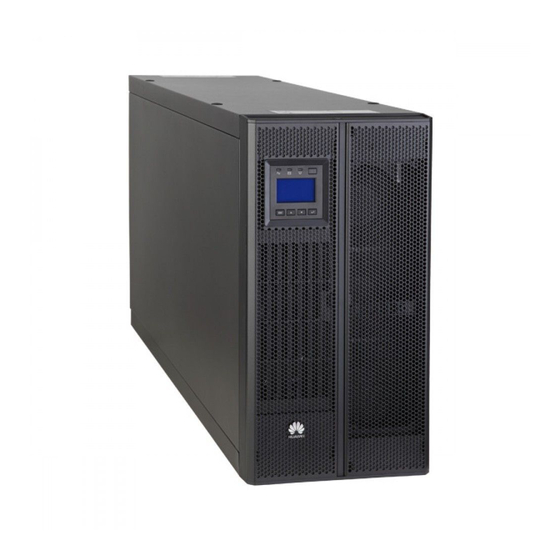
UPS5000-A-(60 kVA-120 kVA)-H User Manual 2 Overview Figure 2-8 UPS5000-A-60 kVA/120 kVA (1) Front panel 1 (2) MDU (3) Front panel 2 (4) Leveling foot (5) Castor (6) Chassis 2.3.2 Product Structure The UPS functional components include the power input and output terminals, communications slots, basic dry contacts, and monitoring bus that controls the expansion of optional components and monitors UPSs. - Page 29 UPS5000-A-(60 kVA-120 kVA)-H User Manual 2 Overview Figure 2-9 UPS5000-A-60 kVA/ 120 kVA structure (front view) (1) Bypass unit indicators (2) MDU port (3) Bypass unit ready switch (4) MDU reset button (5) DIP switch (6) Power unit indicators (7) Power unit ready...
- Page 30 UPS5000-A-(60 kVA-120 kVA)-H User Manual 2 Overview Figure 2-10 UPS5000-A-60 kVA/120 kVA structure (rear view and enlarged view of certain parts) (1) Dry (2) Battery (3) Port for an ambient (4) FE port (upper) contacts temperature temperature and humidity sensor...
- Page 31 Restore Default parameters, Settings monitoring parameters, and logs (including operation logs, upgrade logs, battery tests, and statistics logs). The MDU does not automatically restart. The settings take effect after the Issue 05 (2020-01-10) Copyright © Huawei Technologies Co., Ltd.
-
Page 32: Control Port
Status 8 Reserved 2.3.3 Control Port The UPS5000-A provides a communications slot, a fast Ethernet (FE) port, an RS485 port, parallel ports, a BSC port, basic dry contacts, and other control signal ports. Parallel Port and BSC Port To connect UPSs in parallel, use a parallel cable to connect the parallel ports on the ECMs on the two UPSs. - Page 33 (BCB) box. Grounded: BCB box connected Floated: BCB box not connected The initial status is Grounded. BCB_STA Monitors the battery circuit Status: breaker. Closed: battery circuit breaker ON Issue 05 (2020-01-10) Copyright © Huawei Technologies Co., Ltd.
- Page 34 When the dry contact signal cable of an external device connects to UPS dry contacts, ensure that the silk screen names of the dry contacts at both ends of the cable match with each other. Others Table 2-6 describes other control signal ports. Issue 05 (2020-01-10) Copyright © Huawei Technologies Co., Ltd.
- Page 35 RS485 Connects to a northbound network management port device or third-party network management device over two wires. Figure 2-11 COM1 pins Table 2-7 COM1 pin definition Description RS485- RS485+ 12V_PORT Issue 05 (2020-01-10) Copyright © Huawei Technologies Co., Ltd.
-
Page 36: Typical Configurations
RS485+. Twist cables to pin 2 and pin 5 into one cable and then connect it to RS485–. 2.4 Typical configurations Table 2-9 Typical UPS configurations Configuration Application Scenario Single UPS Supplies power to common loads. Issue 05 (2020-01-10) Copyright © Huawei Technologies Co., Ltd. -
Page 37: Single Ups
LCD or WebUI. 2.4.1 Single UPS The UPS5000-A is a high frequency tower-mounted UPS. It uses a unit-level design to handle power functionality, and provides an embedded maintenance bypass switch to ensure maintenance with power on. -
Page 38: Dual-Bus System
An optional static transfer switch (STS) can be installed to start the bus synchronization controller (BSC). The UPS systems work in normal mode or bypass mode. Issue 05 (2020-01-10) Copyright © Huawei Technologies Co., Ltd. -
Page 39: Optional Components
User Manual 2 Overview Figure 2-14 Conceptual diagram of a dual-bus system 2.5 Optional Components The UPS5000-A provides a variety of optional components to address various customer requirements. Table 2-10 describes the optional components. Table 2-10 Optional components of the UPS5000-A... - Page 40 Communicates with the UPS over Modbus. Parallel cable 5 m/10 m/15 m Connects UPSs in parallel. BSC cable 5 m/10 m/15 m/60 Transmits bus synchronization signals in a dual-bus Issue 05 (2020-01-10) Copyright © Huawei Technologies Co., Ltd.
- Page 41 UPS5000-A-(60 kVA-120 kVA)-H User Manual 2 Overview Optional Model Function Reference Component Document system. Issue 05 (2020-01-10) Copyright © Huawei Technologies Co., Ltd.
-
Page 42: Installation
The weight of batteries and battery racks depends on the site requirements. Table 3-1 lists the UPS weight. Table 3-1 UPS5000-A weight Capacity Weight 60 kVA 140 kg 120 kVA 170 kg Figure 3-1 shows the installation dimensions. Issue 05 (2020-01-10) Copyright © Huawei Technologies Co., Ltd. - Page 43 UPS5000-A-(60 kVA-120 kVA)-H User Manual 3 Installation Figure 3-1 Installation dimensions of the UPS5000-A-60 kVA/120 kVA (unit: mm) Installation Environment Do not install the UPS in high temperature, low temperature, and damp areas. Install the UPS far away from water sources, heat sources, and inflammable or explosive materials.
-
Page 44: Tools And Instruments
Table 3-2 Tools and meters Tools and Meters Electric pallet truck Manual pallet truck Ladder Rubber mallet Hammer drill and Hand-held electric Alloy hole saw Heat gun drill bit Φ16 drill Issue 05 (2020-01-10) Copyright © Huawei Technologies Co., Ltd. - Page 45 Protective gloves Insulated gloves Insulation protective shoes discharge (ESD) gloves Torque screwdriver Cable cutter Brush Flat-head screwdriver (2–5 mm) Phillips screwdriver Insulated torque Heat shrink tubing Insulated adjustable wrench wrench (M3/M4/M5/M6/M (M6/M8/M12/M16) Issue 05 (2020-01-10) Copyright © Huawei Technologies Co., Ltd.
-
Page 46: Preparing Power Cables
(mm 1 x 16 1 x 50 Bypass Bypass input current (A) input Recommended cross- 4 x 35 4 x 70 sectional area (mm 1 x 16 1 x 50 Issue 05 (2020-01-10) Copyright © Huawei Technologies Co., Ltd. - Page 47 Maximum battery discharge current: the current upon end of discharge when forty 12 V batteries are configured, namely, discharge current in the case of 240 2 V battery cells with 1.67 V/cell. Issue 05 (2020-01-10) Copyright © Huawei Technologies Co., Ltd.
- Page 48 Bypass input M10 x 30 11 mm 55N•m Battery input M12 x 45 13 mm 35N•m Output M10 x 30 11 mm 60 kVA/120 M8 x 20 9 mm 13 N· m Issue 05 (2020-01-10) Copyright © Huawei Technologies Co., Ltd.
- Page 49 UPS5000-A-(60 kVA-120 kVA)-H User Manual 3 Installation Figure 3-3 DT terminal for the UPS5000-A Table 3-5 DT terminal specifications for the UPS5000-A Nomin Bolt ΦH d (mm) D (mm) W (mm) L (mm) (mm) Nominal Devi Nominal Devi Reference Nominal...
-
Page 50: Transportation And Unpacking
If multiple loads are connected, specifications for branch circuit breakers must not exceed the recommended specifications. The circuit breaker selection principle is to protect loads and cables, and the cascading principle is to realize specific protection. 3.1.4 Transportation and Unpacking Prerequisites Issue 05 (2020-01-10) Copyright © Huawei Technologies Co., Ltd. - Page 51 Removing binding straps. Figure 3-4 Removing binding straps Issue 05 (2020-01-10) Copyright © Huawei Technologies Co., Ltd.
- Page 52 Check that the fittings comply with the packing list. If some fittings are missing or do not comply with the packing list, record the information and contact your local Huawei office immediately. Step 7 After checking that the equipment is intact, remove the UPS front panels, as shown in Removing UPS front panels.
- Page 53 Before removing the lower front panel, disconnect the ground cable connected to the chassis. Step 8 Remove the L-shaped brackets that secure the chassis to the pallet, as shown in Removing L- shaped brackets. Issue 05 (2020-01-10) Copyright © Huawei Technologies Co., Ltd.
-
Page 54: Installing A Single Ups
Step 1 Lower the four leveling feet at the bottom of the UPS using a wrench until all the four castors at the bottom hang in the air and the leveling feet bear the whole cabinet weight, as shown in Figure 3-8. Issue 05 (2020-01-10) Copyright © Huawei Technologies Co., Ltd. - Page 55 L-shaped brackets. Step 1 Determine the position for installing the UPS. Mark mounting holes and their dimensions based on the marking-off template, as shown in Figure 3-10. Issue 05 (2020-01-10) Copyright © Huawei Technologies Co., Ltd.
- Page 56 Figure 3-11 shows the expansion bolt composition. Figure 3-12 shows how to install an expansion bolt. Figure 3-11 Expansion bolt (1) M12 bolt (2) Spring washer (3) Flat washer (4) Expansion sleeve Issue 05 (2020-01-10) Copyright © Huawei Technologies Co., Ltd.
- Page 57 Figure 3-8. Step 5 Secure the two L-shaped brackets to the front and rear of the chassis using eight M6 screws, as shown in Figure 3-13. Issue 05 (2020-01-10) Copyright © Huawei Technologies Co., Ltd.
- Page 58 Figure 3-14 Securing the L-shaped bracket to the ground (front view) Step 9 (Recommended) Install a lock for the maintenance bypass switch, as shown in Figure 3-9. ----End Rack-mounting the UPS Issue 05 (2020-01-10) Copyright © Huawei Technologies Co., Ltd.
- Page 59 (1) Scale (2) Mounting ear (3) Lower edge of a U scale Use panel screws to secure the front and rear ends of the guide rail, as shown in Figure 3-16. Issue 05 (2020-01-10) Copyright © Huawei Technologies Co., Ltd.
- Page 60 Step 3 Install four floating nuts respectively on the left and right mounting bars on the front of the rack. Use a scale plate to determine the installation positions of floating nuts. Figure 3-18 shows a scale plate. Issue 05 (2020-01-10) Copyright © Huawei Technologies Co., Ltd.
- Page 61 Install floating nuts onto the mounting holes for the mounting bar that corresponds to Hole location lines. Figure 3-18 Scale plate Install floating nuts, as shown in Figure 3-19. Figure 3-20 shows the installation positions of floating nuts. Figure 3-19 Installing a floating nut Issue 05 (2020-01-10) Copyright © Huawei Technologies Co., Ltd.
- Page 62 3-21. Before moving the power units, rotate the ready switch to the unlocked state. Two persons are required to move a power unit. Keep the power units at the same level during movement. Issue 05 (2020-01-10) Copyright © Huawei Technologies Co., Ltd.
- Page 63 Remove the power units. Step 5 Install mounting ears on the chassis, two on the left and two on the right, as shown in Figure 3-22. Figure 3-22 Installing mounting ears Issue 05 (2020-01-10) Copyright © Huawei Technologies Co., Ltd.
- Page 64 Step 7 Adjust the four leveling feet using an adjustable wrench until the bottom of the original chassis is level with the Edge of cabinet line on the scale plate, as shown in Figure 3-24. Issue 05 (2020-01-10) Copyright © Huawei Technologies Co., Ltd.
- Page 65 Step 8 Check the cabinet levelness using a level. If the cabinet is not leveled, adjust the leveling feet. Step 9 Secure the chassis to the rack, as shown in Figure 3-25. Issue 05 (2020-01-10) Copyright © Huawei Technologies Co., Ltd.
-
Page 66: Optional) Installing Antiseismic Kits
Step 4 Remove the lower front panel of the UPS and PDU cover. Step 5 Secure two antiseismic kits to the front and rear of the chassis using eight M6 screws and four M12 screws. Issue 05 (2020-01-10) Copyright © Huawei Technologies Co., Ltd. -
Page 67: Optional) Installing A Battery Monitoring Unit
When an ambient temperature and humidity sensor is installed, connect the BMU to the RS485_OUT port on the sensor. Figure 3-28 shows the position of the BMU on the UPS. Issue 05 (2020-01-10) Copyright © Huawei Technologies Co., Ltd. - Page 68 UPS5000-A-(60 kVA-120 kVA)-H User Manual 3 Installation Figure 3-27 Connecting the UPS and BMU (without ambient temperature and humidity sensor) Figure 3-28 Connecting the UPS and BMU (with ambient temperature and humidity sensor) Issue 05 (2020-01-10) Copyright © Huawei Technologies Co., Ltd.
-
Page 69: Installing Batteries
3 h > Backup time ≥ 1 h: Set the EOD threshold to 1.75 V/cell. Backup time ≥ 3 h: Set the EOD threshold to 1.80 V/cell. Step 3 (Optional) Install a BBB box. ----End 3.2.5 UPS Cable Connection Reference Context Issue 05 (2020-01-10) Copyright © Huawei Technologies Co., Ltd. -
Page 70: Routing Cables
Step 5 Clean foreign matter inside the cabinet. ----End 3.2.6 Routing Cables This section describes how to connect cables for the UPS5000-A-120K. The cable connection method is the same for the UPS5000-A-60K and UPS5000-A-120K. Issue 05 (2020-01-10) Copyright © Huawei Technologies Co., Ltd. -
Page 71: Cable Routes
Remove 1–3 covers from the bottom of the cabinet based on the number and positions of cables, as shown in Figure 3-31. Figure 3-31 Removing small covers from the bottom of the cabinet Figure 3-32 shows the power cables routed from the bottom of the cabinet. Issue 05 (2020-01-10) Copyright © Huawei Technologies Co., Ltd. -
Page 72: Connecting Ground Cables
Determine the required number of ground cables based on Table 3-3 and the site requirements. The following information is for your reference. The basic rule for routing cables is: from inside out and from bottom up. Issue 05 (2020-01-10) Copyright © Huawei Technologies Co., Ltd. -
Page 73: Connecting Ac Input Power Cables
No copper bars are required. The neutral bar is near the cabinet interior. To facilitate cabling, you are advised to connect the neutral wire before connecting other wires. Issue 05 (2020-01-10) Copyright © Huawei Technologies Co., Ltd. - Page 74 Figure 3-35. Figure 3-35 Removing copper bars Step 2 Connect the mains input power cable to mains power distribution wiring terminals N, 1L1, 1L2, and 1L3, as shown in Figure 3-36. Issue 05 (2020-01-10) Copyright © Huawei Technologies Co., Ltd.
- Page 75 Step 3 Connect the bypass input power cable to bypass power distribution wiring terminals N, 2L1, 2L2, and 2L3, as shown in Figure 3-37. Figure 3-37 Connect the bypass input power cable ----End Issue 05 (2020-01-10) Copyright © Huawei Technologies Co., Ltd.
-
Page 76: Connecting Ac Output Power Cables
Ensure that cables are correctly connected between battery strings and the battery switch, and between the battery switch and the UPS. Avoid inverse connections. Connect the battery cables to battery power distribution wiring terminals +, N, and –, as shown in Figure 3-39. Issue 05 (2020-01-10) Copyright © Huawei Technologies Co., Ltd. -
Page 77: Connecting Signal Cables
40 batteries, half positive and half negative. Figure 3-40 Neutral wire 3.2.6.6 Connecting Signal Cables Remote EPO Issue 05 (2020-01-10) Copyright © Huawei Technologies Co., Ltd. - Page 78 UPS5000-A-(60 kVA-120 kVA)-H User Manual 3 Installation Huawei does not provide the EPO switch or cable. Prepare them by yourself. The recommended cable is 22 AWG. Equip the EPO switch with a protective cover to prevent misoperations, and cover the cable with protective tubing.
- Page 79 Step 3 (Optional) Connect the RJ11 port on the temperature and humidity sensor to the COM1 port. Figure 3-43 shows the RS485 port pins and Table 3-9 describes the pin definitions. Issue 05 (2020-01-10) Copyright © Huawei Technologies Co., Ltd.
-
Page 80: Installing A Parallel System
Step 5 Choose a parallel mode and connect cables to the parallel system based on site requirements. Figure 3-44 Figure 3-45 show the typical conceptual diagram and cable connections for a 1+1 parallel system. Issue 05 (2020-01-10) Copyright © Huawei Technologies Co., Ltd. - Page 81 Do not configure circuit breakers for the mains and bypass input N wires and output N wire. Connect power cables according to port silk screen. Issue 05 (2020-01-10) Copyright © Huawei Technologies Co., Ltd.
- Page 82 Figure 3-46 Figure 3-47 show the conceptual diagram and cable connections for a dual- bus parallel system consisting of two UPS systems. Figure 3-46 Conceptual diagram of a dual-bus parallel system Issue 05 (2020-01-10) Copyright © Huawei Technologies Co., Ltd.
-
Page 83: Connecting Signal Cables
To connect signal cables in a parallel system, perform the following steps: Connect the parallel ports on the UPSs over parallel cables to create a loop. N+X parallel system. Figure 3-48 shows cable connections. Issue 05 (2020-01-10) Copyright © Huawei Technologies Co., Ltd. - Page 84 In a dual-bus parallel system, BSC cables need to be connected to the master and slave systems. Figure 3-50 shows cable connections in the scenario where the master system consists of two UPSs. Figure 3-50 Parallel cable connections in a dual-bus system Issue 05 (2020-01-10) Copyright © Huawei Technologies Co., Ltd.
-
Page 85: Installation Verification
Correct cable connections Cables are properly connected according to wiring diagrams. Connections of live wires and Connections for mains input terminals 1L1, 1L2, 1L3, and N, bypass input terminals 2L1, Issue 05 (2020-01-10) Copyright © Huawei Technologies Co., Ltd. - Page 86 After routing cables and verifying the installation, use sealing putty to seal the gaps between the cables and the cabinet. After verifying the installation, reinstall all the covers. Do not remove the dustproof cover before power-on to prevent dust from entering the UPS. Issue 05 (2020-01-10) Copyright © Huawei Technologies Co., Ltd.
- Page 87 (2) AC output wiring (3) Bypass input wiring terminals terminals (4) Mains input wiring (5) UPS bottom terminals Figure 3-52 Fill the holes with sealing putty (1) Paper protective film (2) Sealing putty Issue 05 (2020-01-10) Copyright © Huawei Technologies Co., Ltd.
-
Page 88: Lcd And Webui
Figure 4-1 MDU panel (1) LCD (2) Back/Shutdown button (3) Up button (4) Down button (5) Startup/Enter/Mute button (6) Fault indicator/INFO button (7) Bypass indicator (8) Battery indicator (9) Mains indicator Issue 05 (2020-01-10) Copyright © Huawei Technologies Co., Ltd. - Page 89 On the shutdown screen displayed, press The inverter shuts down. ▲ Press ▲ or ▼ to scroll upward or downward. Set parameters by using the list or step increase or ▼ Down decrease. Issue 05 (2020-01-10) Copyright © Huawei Technologies Co., Ltd.
-
Page 90: Lcd
If you do not press any button within 60s, the default screen is displayed. After login, if you do not press any button within 60s, you are logged out. 4.2 LCD 4.2.1 Overview Symbol Meaning Table 4-3 Symbol conventions Symbol Meaning Press A. Press A and then B. Issue 05 (2020-01-10) Copyright © Huawei Technologies Co., Ltd. -
Page 91: Status Screen
Table 4-4 Mains Input Item Description Van, Vbn, and Vcn Mains input phase voltages Ia, Ib, and Ic Mains input phase currents Frequency Mains input frequency Vab, Vbc, and Vca Mains input line voltages Issue 05 (2020-01-10) Copyright © Huawei Technologies Co., Ltd. - Page 92 UPS output phase current Power factor_A, Power Proportion of passive power to apparent power for each factor_B, and Power factor_C phase Frequency UPS output frequency Vab, Vbc, and Vca UPS output line voltages Issue 05 (2020-01-10) Copyright © Huawei Technologies Co., Ltd.
- Page 93 If there is no such sensor, NA is displayed. Table 4-11 Runtime Item Description Inv. runtime Time for which the UPS runs in normal mode BPM runtime Time for which the UPS runs in bypass mode Issue 05 (2020-01-10) Copyright © Huawei Technologies Co., Ltd.
-
Page 94: Alarms
Select Clear Faults and press . The login screen for accessing the Clear Faults screen is displayed. Enter the preset password 000001 and press . The Clear Faults screen is displayed. Issue 05 (2020-01-10) Copyright © Huawei Technologies Co., Ltd. -
Page 95: Settings Screen
On the Main Menu screen, select Settings, and press . On the login screen displayed, enter the password (preset password: 000001), and press . The Settings screen is displayed. Figure 4-6 Settings screen Issue 05 (2020-01-10) Copyright © Huawei Technologies Co., Ltd. - Page 96 Supports 12 English English, Chinese, Spanish, Dutch, French, display German, Italian, Polish, Portuguese, languages Russian, Swedish, and Turkish Password 000001 Communication Settings Figure 4-8 Comm Settings screen Figure 4-9 IP settings Issue 05 (2020-01-10) Copyright © Huawei Technologies Co., Ltd.
- Page 97 Verify the validity of RS485 None None, Odd, Even communication characters. When a device node adopts RS485 communication, ensure that the parity modes for the device nodes are set to the same mode. Issue 05 (2020-01-10) Copyright © Huawei Technologies Co., Ltd.
- Page 98 Number of cascaded ambient 0–4 temperature and humidity sensors Figure 4-12 Battery temperature sensor Item Description Default Value Value Range Start address 16–28 Quantity Number of cascaded battery 0–4 temperature sensors Issue 05 (2020-01-10) Copyright © Huawei Technologies Co., Ltd.
- Page 99 In ECO mode, when the ± 5% ± 5%, ± 6%, ± 7%, range difference between the bypass ± 8%, ± 9%, voltage and the rated voltage is ± 10% greater than this value, the Issue 05 (2020-01-10) Copyright © Huawei Technologies Co., Ltd.
- Page 100 Disabled, temperature sensor monitors the Enabled ambient temperature near batteries, and ensures that batteries work reliably and securely. Input Settings It is recommended that you retain the default input parameter settings. Issue 05 (2020-01-10) Copyright © Huawei Technologies Co., Ltd.
- Page 101 (If the voltage level is 380 V or 400 V, the default upper limit is +15%. If the voltage level is 415 V, the default upper limit is +10%.) Issue 05 (2020-01-10) Copyright © Huawei Technologies Co., Ltd.
- Page 102 Description Default Value Value Range Max. voltage When the difference between the When the voltage level is 380 V, bypass voltage and the rated the value range is +10%, +15%, Issue 05 (2020-01-10) Copyright © Huawei Technologies Co., Ltd.
- Page 103 When Single/Parallel is set to Single, the Batt. sharing parameter is unavailable. Retain default values for the Cur. Limit coef. and Cell float volt. parameters. Only professional maintenance personnel can change the values. Issue 05 (2020-01-10) Copyright © Huawei Technologies Co., Ltd.
- Page 104 Num of batt. Specifies the number of battery 1–4 strings strings connected in parallel. Maint. period Specifies the interval for 0–365 reminding users of battery maintenance. Issue 05 (2020-01-10) Copyright © Huawei Technologies Co., Ltd.
- Page 105 Figure 4-21 Float Charge screen Item Description Default Value Value Range Cell float volt. Indicates the battery float 2.25 V/cell 2.23 V/cell–2.30 charging voltage. The parameter V/cell is configurable in any mode. Issue 05 (2020-01-10) Copyright © Huawei Technologies Co., Ltd.
- Page 106 Max. dis. time Indicates the maximum battery 0h–48h discharge time. When the discharge time reaches the value, the UPS powers off. Shallow Discharge Test Figure 4-23 Shallow Discharge Test screen Issue 05 (2020-01-10) Copyright © Huawei Technologies Co., Ltd.
- Page 107 Backup time Figure 4-24 Backup time screen Warning thresh. parameter − If the warning function is enabled, a warning is generated when the backup time reaches the specified value. Remaining cap. Issue 05 (2020-01-10) Copyright © Huawei Technologies Co., Ltd.
- Page 108 If the BP/SYSMT switch is set to Enable, the port has dry contact signal access. Using the port depends on the status of the BP/SYSMT switch. BP/SYSMT switch function If the BP/SYSMT switch is set to Enable, this Issue 05 (2020-01-10) Copyright © Huawei Technologies Co., Ltd.
-
Page 109: Control
. The Control screen is displayed. Figure 4-27 Control screen Starting the Inverter You can start the inverter manually by pressing Startup. Shutting Down the Inverter You can shut down the inverter manually by pressing Shutdown. Issue 05 (2020-01-10) Copyright © Huawei Technologies Co., Ltd. -
Page 110: About Screen
You can clear operation logs successfully only after setting DIP1, DIP2, and DIP3 on the DIP switch to OFF, ON, and ON respectively. 4.2.6 About Screen Figure 4-29 shows the About screen. Issue 05 (2020-01-10) Copyright © Huawei Technologies Co., Ltd. -
Page 111: Webui
Step 1 Open the browser and choose Tools > Internet Options. Step 2 On the Advanced tab page, ensure that Use TLS 1.0, and Use TLS 1.1 are selected and click OK, as shown in Figure 4-30. Issue 05 (2020-01-10) Copyright © Huawei Technologies Co., Ltd. - Page 112 (upgrade, calibration, and variables commissioning). operator Changeme Only browses the system running information, exports (common user) system information, starts/shuts down the inverter, rectifies faults, and controls the buzzer. Other control Issue 05 (2020-01-10) Copyright © Huawei Technologies Co., Ltd.
-
Page 113: Monitoring Page
Figure 4-31 numerically labels Monitoring page details and Table 4-13 describes these details. Figure 4-31 Monitoring page If NA is displayed for load ratio, the value is invalid or outside the range. Issue 05 (2020-01-10) Copyright © Huawei Technologies Co., Ltd. -
Page 114: Parameter Settings
When EPO detection is changed from Disable to Enable, check that the EPO cable is connected correctly. D.G. ECO Indicates whether ECO bypass is Enable Disable, Enable bypass supply allowed to supply power in D.G. Issue 05 (2020-01-10) Copyright © Huawei Technologies Co., Ltd. - Page 115 (%) facilitates better cooperation between the UPS and the D.G. Input cur. Specifies whether to enable or Disable Disable, Enable limiting disable input current limiting to protect generators. Issue 05 (2020-01-10) Copyright © Huawei Technologies Co., Ltd.
- Page 116 If Bus overvoltage recovery is set to Enable, the bus overvoltage alarm is automatically cleared, and the rectifier and inverter Issue 05 (2020-01-10) Copyright © Huawei Technologies Co., Ltd.
- Page 117 10%, the system will generate a bypass current imbalance alarm and cannot enter the ECO mode. If this parameter is set to Enable, the preceding detection is not Issue 05 (2020-01-10) Copyright © Huawei Technologies Co., Ltd.
- Page 118 If this parameter is set to Enable, Enable Disable, Enable equalized the UPS automatically changes charging the battery management status to equalized charge based on the charge current and float charge time. Issue 05 (2020-01-10) Copyright © Huawei Technologies Co., Ltd.
- Page 119 EOD threshold, the bypass is disabled, and EOD restart is Enable, the UPS will restart as soon as the mains resumes. If EOD restart is disabled, clear the alarm manually or enable the Issue 05 (2020-01-10) Copyright © Huawei Technologies Co., Ltd.
- Page 120 Enable and the backup time is less than the warning threshold. Remain. cap. An alarm is generated if this Disable Disable, Enable warning parameter is set to Enable and Issue 05 (2020-01-10) Copyright © Huawei Technologies Co., Ltd.
-
Page 121: Communications Settings
4.3.3 Control 4.3.3.1 Historical Alarms Page On the homepage, click the Query tab to open the Historical Alarms page for querying historical alarms based on severity, generation time, and clear time. Issue 05 (2020-01-10) Copyright © Huawei Technologies Co., Ltd. -
Page 122: Logs Page
Historical logs can be exported but not queried. Figure 4-36 Logs Page 4.3.4 Config. Page 4.3.4.1 User Management On the home page, choose Config. > User Mgmt. Issue 05 (2020-01-10) Copyright © Huawei Technologies Co., Ltd. -
Page 123: Site Config
If the password complexity check is enabled, the user password is required to be a string of 6–20 characters and contain at least two types of characters. 4.3.4.2 Site Config. On the home page, choose Config. > Site Config. Issue 05 (2020-01-10) Copyright © Huawei Technologies Co., Ltd. - Page 124 Test to check whether the test email can be received. Configure Alarm Notification Server is used to configure a server for receiving alarm emails from the monitoring system. Issue 05 (2020-01-10) Copyright © Huawei Technologies Co., Ltd.
-
Page 125: Rccmd
Enable upon first login. After you submit the setting, the page refreshes. The controls such as SSL Encrypted Transmission and Event Configuration will be displayed on the page, as shown in Figure 4-40. Figure 4-39 RCCMD function disabled Issue 05 (2020-01-10) Copyright © Huawei Technologies Co., Ltd. - Page 126 Disable, the RCCMD certificate controls will not be displayed on the page, as shown in Figure 4-42. If SSL Encrypted Transmission is set to Disable, a message indicating there is a risk will be displayed. Issue 05 (2020-01-10) Copyright © Huawei Technologies Co., Ltd.
- Page 127 The MDU supports 17 alarm events, and a maximum of 50 jobs can be added for each event, as shown in Figure 4-43. Figure 4-43 shows the buttons on the Event Configuration page, Table 4-14 describes these buttons. Issue 05 (2020-01-10) Copyright © Huawei Technologies Co., Ltd.
- Page 128 Button for deleting all jobs You can delete all jobs of the event by clicking this button. Figure 4-44 shows the buttons after one event is expanded and Table 4-15 describes these buttons. Issue 05 (2020-01-10) Copyright © Huawei Technologies Co., Ltd.
- Page 129 RCCMD Shutdown: You need to specify the RCCMD client IP address and port. When the RCCMD client receives the job, it will shut down the computer. Issue 05 (2020-01-10) Copyright © Huawei Technologies Co., Ltd.
- Page 130 RCCMD Execute: Specify the RCCMD client IP address, port, and command to be executed. For example, enter SHUTDOWN, and the RCCMD client will shut down the computer after receiving the command. Issue 05 (2020-01-10) Copyright © Huawei Technologies Co., Ltd.
- Page 131 UPS input voltage value (for example, single-phase: 220 V; three-phase A: 220 V, B: 220 V, C: 220 V). Table 4-16 lists the signal names that can be entered. Figure 4-48 RCCMD TRAP Issue 05 (2020-01-10) Copyright © Huawei Technologies Co., Ltd.
- Page 132 RCCMD client once. At X seconds remaining time: When the battery backup time has only X seconds left, the job will be sent to the RCCMD client once. Issue 05 (2020-01-10) Copyright © Huawei Technologies Co., Ltd.
-
Page 133: Managing The Ups By Using The Nms Complying With Rfc1628 Standard
The MIB is in the MDU. Click Download UPS-RFC1628-MIB on the page of the web browser to download the MIB file which allows the third-party NMS to manage the UPS remotely. Issue 05 (2020-01-10) Copyright © Huawei Technologies Co., Ltd. - Page 134 Take the UNMS II of Generex for example. The method for managing the UPS by using the UNMS II is the same as the method for managing other devices by using the UNMS II. For details, see the UNMS II user manual. Issue 05 (2020-01-10) Copyright © Huawei Technologies Co., Ltd.
-
Page 135: Protecting The Server By Using The Rccmd Software
If encryption is disabled, you do not need to select the encrypted transmission. All configurations take effect only after restart. Figure 4-52 Setting the MDU IP address and SSL encrypted transmission mode on the RCCMD client Issue 05 (2020-01-10) Copyright © Huawei Technologies Co., Ltd. -
Page 136: Ups Alive Check Function
CS121/UPSMAN Traps. If by polling CS121/UPSMAN every x seconds... is selected as the method of detecting heartbeats, set the detection method. The default interval is 1800s and detection is performed 100 times, as shown in Figure 4-53. Issue 05 (2020-01-10) Copyright © Huawei Technologies Co., Ltd. - Page 137 User Manual 4 LCD and WebUI Figure 4-53 Heartbeat detecting mode on the RCCMD client You can also manually detect heartbeat by clicking Run alive check now..Figure 4-54 Detecting heartbeat manually Issue 05 (2020-01-10) Copyright © Huawei Technologies Co., Ltd.
- Page 138 UPS5000-A-(60 kVA-120 kVA)-H User Manual 4 LCD and WebUI Figure 4-55 Detecting heartbeat manually and successfully ----End Issue 05 (2020-01-10) Copyright © Huawei Technologies Co., Ltd.
-
Page 139: Operations
Procedure Step 1 Close the upstream bypass and mains input switches. After the UPS is powered on, initialization begins. The MDU displays the Huawei logo and an initialization progress bar. Step 2 After the LCD starts properly, perform the following operations: ... - Page 140 UPS (when no battery string is shared). High or low charging power shortens the battery lifespan, or even promptly damages batteries. To determine the battery capacity, contact Huawei technical support.
- Page 141 In the address box of the browser, enter https://UPS IP address. Select a language. Enter a user name and password, and click Login. The system supports Internet Explorer 11 and Firefox 31.0. Issue 05 (2020-01-10) Copyright © Huawei Technologies Co., Ltd.
- Page 142 Power unit. Enter the measured voltages for Ph. A output volt., Ph. B output volt., and Ph. C output volt. under Actual Value and click Submit at the end of each row to commission the voltages. Issue 05 (2020-01-10) Copyright © Huawei Technologies Co., Ltd.
-
Page 143: Shutting Down And Powering Off The Ups
Shut down the inverter on the LCD. On the main menu, choose Control. On the login screen, enter a password. Click Inv. OFF, press to shut down the inverter, as shown in Figure 5-6. Issue 05 (2020-01-10) Copyright © Huawei Technologies Co., Ltd. - Page 144 Step 4 Turn off the battery switch (if there are multiple battery strings, turn off the general switch between battery strings and the UPS and then the switch for each battery string). Step 5 Turn off the external mains and bypass input switches. ----End Issue 05 (2020-01-10) Copyright © Huawei Technologies Co., Ltd.
-
Page 145: Starting The Ups In Battery Mode
Step 4 Press and hold down the BATT START button on the bypass unit for at least 2 seconds. The system automatically enters the battery cold start status. The LCD displays the Huawei logo and an initialization progress bar. -
Page 146: Testing Batteries
If the inverter has not started, the inverter cannot supply power immediately when the bypass becomes abnormal and the UPS may power off. ----End 5.6 Testing Batteries 5.6.1 Forced Equalized Charging Test Context Issue 05 (2020-01-10) Copyright © Huawei Technologies Co., Ltd. -
Page 147: Shallow Discharge Test
Before conducting a shallow discharge test, check whether the requirements of a shallow discharge test are met. If the requirements are met, the button for starting a shallow discharge test is available. Otherwise, the button is unavailable. Issue 05 (2020-01-10) Copyright © Huawei Technologies Co., Ltd. - Page 148 The battery discharge capacity reaches the specified value (10%–50%, 20% by default). The discharge voltage reaches the warning threshold (calculated in real time). The load ratio fluctuation exceeds 10%. An alarm is generated. ----End Issue 05 (2020-01-10) Copyright © Huawei Technologies Co., Ltd.
-
Page 149: Capacity Test
Save the capacity test data record with the largest discharge capacity in a month as the capacity test data for the month. A maximum of recent 36 capacity test records can be saved. Issue 05 (2020-01-10) Copyright © Huawei Technologies Co., Ltd. -
Page 150: Test Data Download
In maintenance bypass mode, the mains supplies power to the loads over the maintenance bypass. If the mains is abnormal, the loads may power off. Procedure Step 1 Transfer the UPS to bypass mode. Step 2 Turn on the maintenance bypass switch. Issue 05 (2020-01-10) Copyright © Huawei Technologies Co., Ltd. - Page 151 LCD and WebUI, as shown in Figure 5-15 Figure 5-16. Figure 5-15 Maint. breaker closed alarm on the LCD Figure 5-16 Maint. breaker closed alarm on the WebUI ----End Issue 05 (2020-01-10) Copyright © Huawei Technologies Co., Ltd.
-
Page 152: Transferring From Maintenance Bypass Mode To Normal Mode
LCD or WebUI to check that the UPS has transferred to bypass mode. Figure 5-17 Turning off the maintenance bypass switch Step 2 Start the inverter. ----End 5.9 Performing EPO Context Issue 05 (2020-01-10) Copyright © Huawei Technologies Co., Ltd. -
Page 153: Clearing The Epo State
On the main screen, choose Alarms > Clear Faults. After the dialog box is displayed, press and the EPO alarm can be cleared, as shown in Figure 5-20 Figure 5-21. Issue 05 (2020-01-10) Copyright © Huawei Technologies Co., Ltd. - Page 154 Figure 5-22 Clearing the alarm on the WebUI Step 3 Check that the EPO alarm has disappeared from the alarm list. If the bypass is normal, the UPS transfers to bypass mode. Step 4 Start the inverter. ----End Issue 05 (2020-01-10) Copyright © Huawei Technologies Co., Ltd.
-
Page 155: Routine Maintenance
Input voltage: 380 V AC, 400 If the input voltage is environment V AC, or 415 V AC (line abnormal, check the power grid voltage) status and input cable Issue 05 (2020-01-10) Copyright © Huawei Technologies Co., Ltd. -
Page 156: Quarterly Maintenance
The insulation layer of Replace the cables. (between the UPS and the cables is intact and terminals Secure the output power distribution cabinet) are free from black marks terminals. Issue 05 (2020-01-10) Copyright © Huawei Technologies Co., Ltd. -
Page 157: Battery Maintenance
When moving batteries, avoid handling the battery upside down, handle batteries gently, and pay attention to personal safety. Keep the battery switch off when installing or maintaining the batteries. Issue 05 (2020-01-10) Copyright © Huawei Technologies Co., Ltd. -
Page 158: Precautions For Battery Maintenance
UPS is excessively long, or the cable diameter is excessively small. 2. Check whether the equalized charging voltage and float Issue 05 (2020-01-10) Copyright © Huawei Technologies Co., Ltd. -
Page 159: Quarterly Maintenance
UPS is backed the fault (for abnormal up to verify that the batteries alarms, see the alarm list). can discharge normally. 2. If the fault persists, contact Huawei technical support. Issue 05 (2020-01-10) Copyright © Huawei Technologies Co., Ltd. -
Page 160: Annual Maintenance
(A torque wrench is used for checking the torque. After checking that the battery screws meet the requirements, mark the screws for later check.) Issue 05 (2020-01-10) Copyright © Huawei Technologies Co., Ltd. -
Page 161: Troubleshooting
EOD voltage and 11.3 V/cell. For details about how to rectify common faults, see Table 7-1. If any unmentioned faults occur, see the alarm list chapter, or contact Huawei technical support. Table 7-1 Solutions to common faults Case Symptom... - Page 162 Fault indicator is on. damaged. The bypass unit experiences Reduce the load, or improve normal. overtemperature. ventilation. For details about component replacement and maintenance involved in Troubleshooting and Alarm List, consult Huawei maintenance engineers. Issue 05 (2020-01-10) Copyright © Huawei Technologies Co., Ltd.
-
Page 163: Technical Specifications
750 V AC/160 A/3P 1000 V AC/200 A/3P 8.3 Environmental Specifications Item 60 kVA 120 kVA Operating temperature 0–40° C –40° C to +70° C Storage temperature Humidity 0%–95% RH (non-condensing) Altitude 0–1000 m Issue 05 (2020-01-10) Copyright © Huawei Technologies Co., Ltd. -
Page 164: Safety Regulations And Emc
If the temperature is 0–30° C, the UPS power is not derated when the voltage is within 187–280 V AC; the load is derated to 35% when the voltage is within 187–80 V AC. Rated frequency 50 Hz/60 Hz Issue 05 (2020-01-10) Copyright © Huawei Technologies Co., Ltd. -
Page 165: Bypass Input Electrical Specifications
Battery string sharing Battery string sharing is supported in a parallel system. No battery is shared by default. Charging voltage Equalized charging voltage: 2.3–2.4 V/cell. The default voltage is 2.35 V/cell (30–42 Issue 05 (2020-01-10) Copyright © Huawei Technologies Co., Ltd. -
Page 166: Output Electrical Specifications
30–40° C: transfer to bypass mode after 3 minutes − 125% < Load ratio ≤ 150%: transfer to bypass mode after 30 seconds Load ratio > 150%, and short circuit: run for 200 ms Issue 05 (2020-01-10) Copyright © Huawei Technologies Co., Ltd. -
Page 167: System Electrical Specifications
UPS5000-A-(60 kVA-120 kVA)-H User Manual 8 Technical Specifications 8.9 System Electrical Specifications Item 60 kVA 120 kVA Parallel system Redundancy design for parallel signals reliability Parallel system ECO Supported Issue 05 (2020-01-10) Copyright © Huawei Technologies Co., Ltd. -
Page 168: A Menu Hierarchy
Parallel-System Load Environment Monitoring Runtime Alarms Active Alarms Hist. Alarms Sort Alarms Clear Faults Control Buzzer Settings User Settings Comm Settings System Settings Input Settings Output Settings Bypass Settings Battery Settings Issue 05 (2020-01-10) Copyright © Huawei Technologies Co., Ltd. -
Page 169: Menus On The Webui
A.2 Menus on the WebUI Level-1 Menu Level-2 Menu Level-3 Menu Monitoring Active Alarms Real-time Data Module Param. Settings System Settings Input Settings Output Settings Bypass Settings Battery Settings Dry Contacts Comm. Config. IP Settings Issue 05 (2020-01-10) Copyright © Huawei Technologies Co., Ltd. - Page 170 SNMP Trap Certificate Management Configuration Management Multi-brand Management Configure Alarm Notification Server Configure Alarm Notification Email Address ModbusTCP Certificate Management ModbusTCP CA Certificate Management ModbusTCP Authentication eUPS Certificate Management RCCMD RCCMD Issue 05 (2020-01-10) Copyright © Huawei Technologies Co., Ltd.
- Page 171 UPS5000-A-(60 kVA-120 kVA)-H User Manual A Menu Hierarchy Level-1 Menu Level-2 Menu Level-3 Menu SSL Encrypted Transmission Event Configuration RCCMD Certificate Management Maint. Calib Module Commissioning Var. Module Upgrade Software BSP Upgrade Download Issue 05 (2020-01-10) Copyright © Huawei Technologies Co., Ltd.
-
Page 172: B Alarm List
Verify the cable connections. Reversed incorrect. 1. Secure or connect the neutral wire 0005-1 Mains neutral Minor Cable connections are to the cabinet if it is loose or absent incorrect. disconnected. Issue 05 (2020-01-10) Copyright © Huawei Technologies Co., Ltd. - Page 173 The battery voltage If the BCB box is configured, check reaches the EOD whether the BCB box trips. If it trips, voltage threshold due close the BCB box switch. to continuous Issue 05 (2020-01-10) Copyright © Huawei Technologies Co., Ltd.
- Page 174 If yes, disable it and check whether the alarm is cleared. If the alarm persists, the dry contact board may be faulty. Replace the board. Issue 05 (2020-01-10) Copyright © Huawei Technologies Co., Ltd.
- Page 175 0047-1 Not ready Critical The ready switch is Close the ready switch. OFF. 1. Check load cable distributions. 0060-4 Inverter Critical A load short- Issue 05 (2020-01-10) Copyright © Huawei Technologies Co., Ltd.
- Page 176 1. Check the bypass fan and air 0570-4 BPM unit Critical The bypass fan is channel. If the fan is faulty, abnormal not functioning replace it. properly, or the air Issue 05 (2020-01-10) Copyright © Huawei Technologies Co., Ltd.
- Page 177 Restore the EPO button status. Start pressed. the UPS after the alarm is cleared. 0086-1 Max. number Minor The system Check the load. of BPM frequently transfers to transfers bypass mode due to overload timeout or Issue 05 (2020-01-10) Copyright © Huawei Technologies Co., Ltd.
- Page 178 ON. 0335 Generator Warning The generator is Running status displayed. No connected connected. suggested measures. 1. Reduce the load. 0594-1 Insufficient Minor The load is Issue 05 (2020-01-10) Copyright © Huawei Technologies Co., Ltd.
- Page 179 2. Check the parameter settings. Parameters are set incorrectly. 1. Shut down the inverter and then 0102-1 Maint. breaker Critical The user operation is close the maintenance circuit misoperation incorrect. breaker. Issue 05 (2020-01-10) Copyright © Huawei Technologies Co., Ltd.
- Page 180 (Alarm ID-Cause 2. After maintenance, open the maintenance circuit breaker and then start the inverter. 0380 In self-check Warning The inverter is in Wait until the inverter self-check is self-check. complete. Issue 05 (2020-01-10) Copyright © Huawei Technologies Co., Ltd.
-
Page 181: C Acronyms And Abbreviations
Conformite Europeenne direct current D.G. diesel generator dual in-line package digital signal processing energy control module economic control operation electromagnetic compatibility end of discharge emergency power off Issue 05 (2020-01-10) Copyright © Huawei Technologies Co., Ltd. - Page 182 Recommended Standard 485 RS485 SNMP Simple Network Management Protocol state of charge Secure Sockets Layer static transfer switch THDi total distortion of the input current waveform THDv total harmonic distortion of output voltage Issue 05 (2020-01-10) Copyright © Huawei Technologies Co., Ltd.
- Page 183 UPS5000-A-(60 kVA-120 kVA)-H User Manual C Acronyms and Abbreviations user interface uninterruptible power system valve regulated lead acid VRLA Issue 05 (2020-01-10) Copyright © Huawei Technologies Co., Ltd.
Need help?
Do you have a question about the UPS5000-A and is the answer not in the manual?
Questions and answers