Table of Contents

Related Manuals for Zte ZXHN H298N


Summary of Contents for Zte ZXHN H298N
- Page 1 ZXHN H298N Home Gateway Maintenance Manual Version: V1.1 ZTE CORPORATION NO. 55, Hi-tech Road South, ShenZhen, P.R.China Postcode: 518057 Tel: +86-755-26770800 Fax: +86-755-26770801 URL: http://ensupport.zte.com.cn E-mail: 800@zte.com.cn...
- Page 2 ZTE CORPORATION or its licensors may have current or pending intellectual property rights or applications covering the subject matter of this document. Except as expressly provided in any written license between ZTE CORPORATION and its licensee, the user of this document shall not acquire any license to the subject matter herein.
-
Page 3: Table Of Contents
Contents About This Manual..................7 Declaration of RoHS Compliance ............10 Safety Precautions ...................11 1 Overview ....................12 1.1 Product Introduction ................12 1.2 Packing List ..................12 1.3 Product Features ................... 13 1.4 Interfaces and Buttons ................14 1.5 Indicators .................... 16 1.6 Technical Specifications ................ - Page 4 4.2 WLAN ....................38 4.2.1 Basic WLAN Configuration..............38 4.2.2 SSID Settings................41 4.2.3 Security..................42 4.2.4 Access Control List ................. 47 4.2.5 Associated Devices ................. 48 4.2.6 WiFi Restrictions ................49 4.3 LAN....................50 4.3.1 DHCP Server ................51 4.3.2 DHCP Server(IPv6) .................
- Page 5 6.1.1 WAN Connection ................77 6.1.2 Advanced ..................78 6.1.3 Fax.................... 80 6.1.4 SIP .................... 82 6.1.5 SIP Accounts ................83 6.1.6 Media ..................85 6.1.7 VoIP Services................87 6.2 DDNS ....................88 6.3 DMZ Host.................... 90 6.4 UPnP....................91 6.5 UPnP Port Mapping ................
- Page 6 7.1.1 Basic..................120 7.1.2 Certificate ................... 121 7.2 User Management ................. 122 7.3 System Management................124 7.3.1 System Management ..............124 7.3.2 Software Upgrade................125 7.3.3 User Configuration Management............125 7.3.4 Default Configuration Management ............126 7.4 Diagnosis ................... 127 7.4.1 Ping Diagnosis ................
-
Page 7: About This Manual
About This Manual Purpose This manual provides procedures and guidelines that support the maintenance of the ZXHN H298N. Intended Audience This document is intended for: Network planning engineer � Installation debugging engineer � On-site maintenance engineer � Network monitoring engineer �... - Page 8 (Application List), and application list. 7, Administration Describes the configuration of TR-069, user management, system management, log management, and system diagnosis. Conventions ZTE documents employ the following typographical conventions. Typeface Meaning Italics References to other Manuals and documents. “Quotes” Links on screens.
- Page 9 Typeface Meaning Click Refers to clicking the primary mouse button (usually the left mouse button) once. Double-click Refers to quickly clicking the primary mouse button (usually the left mouse button) twice. Right-click Refers to clicking the secondary mouse button (usually the right mouse button) once.
-
Page 10: Declaration Of Rohs Compliance
Declaration of RoHS Compliance To minimize the environmental impact and take more responsibility to the earth we live, this document shall serve as formal declaration that the ZXHN H298N manufactured by ZTE CORPORATION is in compliance with the Directive 2002/95/EC of the European Parliament - RoHS (Restriction of Hazardous... -
Page 11: Safety Precautions
Safety Precautions Before using the device, read the following safety precautions. ZTE bears no liability to the consequences incurred by violation of the safety instructions. Read the user manuals before using the device. � Pay attention to all the cautions in the user manuals and on the product. -
Page 12: Overview
Overview 1.1 Product Introduction The ZXHN H298N is an access device. The ZXHN H298N adopts computer network and broadband network access technologies to build a household network center, which interconnects network devices at your home to access the Internet. It provides users with diversified, personalized, convenient, comfortable, safe, and efficient services. -
Page 13: Product Features
RJ-45 network cable RJ-11 telephone cable The ZXHN H298N Home GateWay User Manual is delivered with the product. If any of the components is incorrect, lost, or damaged, contact the product agency. If you want to change the product, keep the packing box and components. -
Page 14: Interfaces And Buttons
� Supporting Interface based marking with 802.1p bit and DSCP � High reliability, simple operation and low power consumption � 1.4 Interfaces and Buttons Figure 1 Figure 2 show the ZXHN H298N interfaces and buttons. Figure 1 Interfaces and Buttons... - Page 15 Figure 2 USB Interface Table 2 describes the ZXHN H298N interfaces and buttons. Table 2 Interfaces and Buttons Interface/Button Description ON/OFF Power button Establish WLAN Push-Button connection. WLAN WLAN button, used to switch on/off WLAN. Reset Reset button, used to restore the factory default settings when pressed for more than 5 seconds in power-ON state.
-
Page 16: Indicators
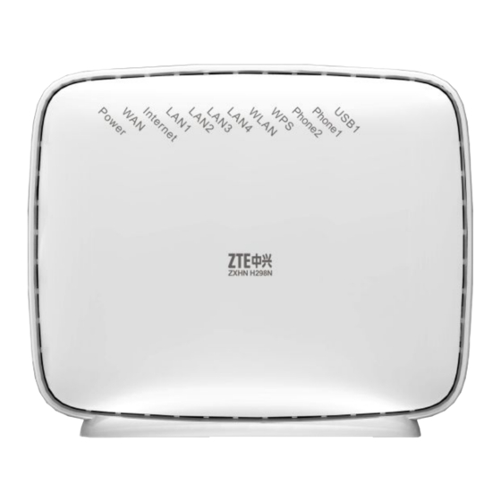
1.5 Indicators Figure 3 shows the ZXHN H298N indicators. Figure 3 Indicators Table 3 describes the indicators on the front panel. Table 3 Indicators on the Front Panel Indicator Color Status Description Power – The device is powered OFF. Green The device is powered ON . -
Page 17: Technical Specifications
However, there is no data flow. USB1 – USB port is disabled or USB device is not connected. Green Flashing Date is transmitting through USB port. USB device is connected and available. 1.6 Technical Specifications Table 4 lists the ZXHN H298N technical specifications. - Page 18 Table 4 Technical Specifications Item Specification Dimensions (Without the base) 170 mm × 56 mm × 140 mm (Length × Width × Height) Rated current Rated voltage 12 V Working temperature 0℃ to 45℃ Working humidity 5% – 95% Storage temperature –40℃...
-
Page 19: Configuration Preparation
Figure 4 Entire Connection 1. USB interface 6. WLAN button 2. Power button 7. LAN interface 3. Reset button 8. WAN interface 4. Power port 9. Phone interface 5. WPS button The connections between the ZXHN H298N and other devices are as follows:... - Page 20 Figure 5 shows the connection between the ZXHN H298N and the telephone. � Figure 5 Telephone Connection...
- Page 21 Figure 6 shows the connection between the ZXHN H298N and the computer. � Figure 6 LAN Interface Connection Figure 7 shows the connection between the ZXHN H298N and the USB storage device. � Figure 7 USB Storage Device Connection...
-
Page 22: Configuring Tcp/Ip
Figure 8 Power Supply Connection To supply power for the device, press the power button on the back of the device. When Internet indicator of the ZXHN H298N indicators is ON, you can access the Internet and use the phone. 2.2 Configuring TCP/IP Perform this procedure to configure TCP/IP. -
Page 23: Logging In To The Device
Before this operation, make sure that the device is properly connected and the computer is correctly configured. Context The ZXHN H298N provides the web-based configuration mode. You can configure and manage the device through the web browser. Different users have different configuration rights, as listed in Table... - Page 24 Steps 1. Open the Internet Explorer. 2. Type on the address bar and press Enter. The login dialog box is displayed, http://192.168.1.1 as shown in Figure Figure 9 Login 3. In Username and Password, type the user name and password (by default, the user name is and the password is ).
-
Page 25: Status
3 3 3 Status 3.1 Device Information Choose [Status→ Device Information]. The device information is displayed, as shown in Figure Figure 11 Device Information Note: The software version and boot loader version may be different from the delivery. 3.2 Network Interface The network interface information includes the following: WAN Connection �... -
Page 26: 4In6 Tunnel Connection
Figure 12 WAN Connection 3.2.2 4in6 Tunnel Connection Choose [Status→ Network Interface→ 4in6 Tunnel Connection]. The 4in6 tunnel connection information is displayed, as shown in Figure Figure 13 4in6 Tunnel Connection... -
Page 27: 6In4 Tunnel Connection
3.2.3 6in4 Tunnel Connection Choose [Status→ Network Interface→ 6in4 Tunnel Connection]. The 6in4 tunnel connection information is displayed, as shown in Figure Figure 14 6in4 Tunnel Connection 3.2.4 Ethernet Choose [Status→ Network Interface→ Ethernet]. The Ethernet information is displayed, as shown Figure... -
Page 28: User Interface
Figure 15 Ethernet 3.3 User Interface The user interface information includes the following: WLAN � Ethernet � � 3.3.1 WLAN Choose [Status→ User Interface→ WLAN]. The WLAN information is displayed, as shown in Figure... -
Page 29: Ethernet
Figure 16 WLAN Status 3.3.2 Ethernet Choose [Status→ User Interface→ Ethernet]. The Ethernet interface information is displayed, as shown in Figure... -
Page 30: Usb
Figure 17 Ethernet Interface Status 3.3.3 USB Choose [Status→ User Interface→ USB]. The interface information is displayed, as shown in Figure... -
Page 31: Voip Status
Figure 18 USB Interface Status Note: application must be configured before you access the USB device. 3.4 VoIP Status Choose [Status→ VoIP Status]. The VoIP service information is displayed, as shown in Figure Figure 19 VoIP Status... -
Page 32: Network
4 4 4 Network 4.1 WAN WAN configuration includes the following: WAN Connection � 4in6 Tunnel Connection � 6in4 Tunnel Connection � Port Binding � 4.1.1 WAN Connection Perform this procedure to configure WAN connection. Steps 1. Choose [Network→ WAN→ WAN Connection]. 2. - Page 33 Figure 20 WAN Connection Table 6 describes the parameters for creating a new WAN connection. Table 6 Parameters for Creating a New WAN Connection Parameter Description Connection Name The default is Create WAN Connection. The connection name is generated automatically. New Connection Name Name the connection.
-
Page 34: 4In6 Tunnel Connection
Parameter Description PPPoE pass-through Enable the PPPoE pass-t;hrough function. Username/Password PPPoE username and password They are provided by the ISP. Authentication Type The type includes Auto, PAP, and CHAP. By default, it is Auto. Connection Trigger There are three connection trigger modes: Always On: When the device is started or gets offline, the �... - Page 35 Figure 21 4in6 Tunnel Connection Table 7 describes the parameters for creating a new 4in6 tunnel connection. Table 7 Parameters for Creating a New 4in6 Tunnel Connection Parameter Description Tunnel Name Tunnel name. The new DS-Lite tunnel (Create Tunnel) or the created DS-Lite tunnel is optional.
-
Page 36: 6In4 Tunnel Connection
3. Click Create. 4.1.3 6in4 Tunnel Connection Perform this procedure to configure 6in4 tunnel connection. Steps 1. Choose [Network→ WAN→ 6in4 Tunnel Connection]. 2. Select Create Tunnel from the Tunnel Name drop-down list, and configure other parameters, as shown in Figure Figure 22 6in4 Tunnel Connection Table 8... -
Page 37: Port Binding
Parameter Description 6in4 Tunnel Type There are two 6in4 tunnel types: Manual Tunnel � � Tunnel Remote Address When Manual Tunnel is selected for 6in4 Tunnel Type, enter the parameter in the Tunnel Remote Address text box. 3. Click Create. 4.1.4 Port Binding Perform this procedure to configure port binding. -
Page 38: Wlan
Port binding is configured. 4.2 WLAN WLAN configuration includes the following: Basic 11n Configuration � SSID Settings � Security � Access Control List � Associated Devices � WiFi Restrictions � 4.2.1 Basic WLAN Configuration Perform this procedure to configure the basic 11n parameters. WLAN basic configuration includes the following modes: IEEE... - Page 39 Figure 24 IEEE 802.11b Only Configuration Table 9 lists the IEEE 802.11b Only parameters. Table 9 IEEE 802.11b Only Parameters Parameter Description Wireless RF Mode Select Enabled to enable the wireless RF function. Enable Isolation When you select this check box, the subscribers with different SSIDs cannot visit each other.
- Page 40 Parameter Description DTIM Interval The value range is from 1 ms to 5 ms. The default is 1 ms. Fragment Threshold When a packet exceeds the fragment threshold, it is divided into multiple packets. Excessive packet fragments may affect the network performance, so the fragment threshold should not be set too big.
-
Page 41: Ssid Settings
3. Click Submit. 4.2.2 SSID Settings Perform this procedure to configure multiple SSIDs. The ZXHN H298N can be specified with four SSIDs and each SSID supports up to 32 subscribers. Steps 1. Choose [Network→ WLAN→ SSID Settings]. 2. Select an SSID from the Choose SSID drop-down list, as shown in... -
Page 42: Security
Figure 26 SSID Settings Table 11 lists the SSID setting parameters. Table 11 Multi-SSID Parameters Parameter Description Choose SSID Select the SSID to be configured. Hide SSID You can hide the SSID to prevent illegal users. Enable SSID Enable the SSID broadcast. Enable SSID Isolation When you select this check box, the subscribers with different SSIDs cannot visit each other. - Page 43 Context The ZXHN H298N provides the following access authentication modes: Open System � Authentication is not needed. Any host with a wireless network card can be connected to the wireless access point. This mode provides encryption. Shared Key � This mode provides WEP encryption.
- Page 44 2. Select Open System from the Authentication Type drop-down list, as shown in Figure Figure 27 Open System Table 12 lists the parameters for the Open System authentication mode. Table 12 Parameters for the Open System Authentication Mode Parameter Description Choose SSID Select a SSID as required.
- Page 45 2. Select Shared Key from the Authentication Type drop-down list, as shown in Figure Figure 28 Shared Key Table 13 lists the parameters for the Shared Key authentication mode. Table 13 Parameters for the Shared Key Authentication Mode Parameter Description Choose SSID Select a SSID as required.
- Page 46 2. Select WPA-PSK from the Authentication Type drop-down list, as shown in Figure Figure 29 WPA-PSK Table 14 lists the parameters for the WPA-PSK authentication mode. Table 14 Parameters for the WPA-PSK Authentication Mode Parameter Description Choose SSID Select a SSID as required. Authentication Type Select WPA-PSK.
-
Page 47: Access Control List
4.2.4 Access Control List Context By default, the function for the ZXHN H298N is disabled. To configure the ACL, perform the following steps: Steps 1. Choose [Network→ WLAN→ Access Control List]. 2. Select a SSID from the Choose SSID drop-down list. Select Disabled, Block, or Permit, as... -
Page 48: Associated Devices
The MAC address that you want to permit or block is displayed on the page, as shown in Figure Figure 31 Access Control List – II ACL is configured. 4.2.5 Associated Devices Context To view the address of the STA that is associated with an SSID, perform the following steps: Steps 1. -
Page 49: Wifi Restrictions
Figure 32 Associated Devices The associated devices are configured. 4.2.6 WiFi Restrictions Context To configure the WiFi restrictions, perform the following steps: Steps 1. Choose [Network→ WLAN→ WiFi Restrictions], as shown in Figure... -
Page 50: Lan
Figure 33 WiFi Restrictions 2. Configure the WiFi off-time and on-time. 3. Click Submit. The WiFi restrictions are configured. 4.3 LAN configuration includes the following: DHCP Server � DHCP Server(IPv6) � DHCP Binding � DHCP Port Service � Static Prefix �... -
Page 51: Dhcp Server
4.3.1 DHCP Server Context To configure the DHCP server, perform the following steps: Steps 1. Choose [Network→ LAN→ DHCP Server]. 2. Set the DHCP server parameters, as shown in Figure Figure 34 DHCP Server Table 16 lists the DHCP server parameters. Table 16 DHCP Server Parameters Parameter Description... -
Page 52: Dhcp Server(Ipv6)
Parameter Description DHCP Start IP DHCP address pool Address/DHCP End IP Address Assign IspDNS Assign the ISP DNS server. DNS Server1 IP IP addresses of the DNS server, provided by the ISP Address–DNS Server3 IP Address Default Gateway It is usually the LAN-side IP address of the device. Lease Time Lease time of the DHCP IP address. -
Page 53: Dhcp Binding
Figure 35 IPv6 DHCP Server Table 17 lists the IPv6 DHCP server parameters. Table 17 IPv6 DHCP Server Parameters Parameter Description LAN IP Address IPv6 address of the device in the LAN Default prefix length: 64 bits Enable DHCP Server Enable the DHCP server. - Page 54 Steps 1. Choose [Network→ LAN→ DHCP Binding]. 2. Set the address and address. The IP address is bound with the MAC address. 3. Click Add. The binding relationship is displayed, as shown in Figure Figure 36 DHCP Binding DHCP binding is configured. Postrequisite You can also modify or delete the DHCP binding relationship, as listed in Table...
-
Page 55: Dhcp Port Service
4.3.4 DHCP Port Service Prerequisite Before this operation, make sure that the global DHCP service is enabled. Steps 1. Choose [Network→ LAN→ DHCP Port Service], as shown in Figure Figure 37 DHCP Port Service 2. Select the interface for which you want to disable the DHCP function. 3. - Page 56 Figure 38 Static Prefix 2. Configure the parameters. Table 19 describes the parameters for static prefix. Table 19 Static Prefix Parameters Parameter Description Prefix IPv6 address Preferred Lifetime Preferred life time of the prefix The length of time that a valid address is preferred (i.e., the time until deprecation).
-
Page 57: Prefix Delegation
3. Click Add. The IPv6 static prefix is configured. 4.3.6 Prefix Delegation Context To configure the IPv6 prefix delegation mode, perform the following steps: Steps 1. Choose [Network→ LAN→Prefix Delegation]. 2. Click to configure the parameters, as shown in Figure Figure 39 Prefix Delegation Table 20 describes the parameters for prefix delegation. -
Page 58: Dhcp Port Service(Ipv6)
Table 20 Prefix Delegation Parameters Parameter Description Connection WAN connection related to the tunnel. Delegation Prefix delegation mode: � DHCPv6 � 3. Click Modify. The prefix delegation mode for a specified WAN connection is configured. 4.3.7 DHCP Port Service(IPv6) Steps 1. -
Page 59: Ra Service
The IPv6 port service is configured. 4.3.8 RA Service Context To configure the wait time in active RA delegation mode, perform the following steps: Steps 1. Choose [Network→ LAN→ RA Service], as shown in Figure Figure 41 RA Service 2. Configure the parameters. Table 21 describes the parameters for the RA service. -
Page 60: Routing(Ipv4)
Parameter Description Managed flag The flag indicates whether or not addresses are to be configured using the stateful autoconfiguration mechanism. OtherConfigFlag The flag indicates whether or not information other than addresses is to be obtained using the stateful autoconfiguration mechanism. 3. -
Page 61: Static Routing
Figure 42 Default Gateway 2. From the WAN Connection drop-down list, select a WAN connection. Note: The WAN Connection drop-down list is displayed by selecting [Network→ WAN→ WAN Connection]. 3. Click Submit. 4.4.2 Static Routing Prerequisite Before this operation, make sure that the WAN connection settings are complete. Context To configure static routing, perform the following steps: Steps... -
Page 62: Policy Routing
Figure 43 Static Routing 2. Configure the parameters. Table 22 describes the parameters for the static routing. Table 22 Parameters for the Static Routing Parameter Description Connection WAN connection for static routing Network Address Destination network address Subnet Mask Subnet mask Gateway Gateway of the network segment which the network interface belongs to... - Page 63 Context Policy routing is a routing rule. When it is configured, the packets are forwarded according to the routing policy. The ZXHN H298N supports packet forwarding according to the DSCP, source or destination address, protocol, source port number, or source address.
-
Page 64: Routing Table
Parameter Description Source Port Source host Port Destination Port Destination host port Source MAC Source MAC address 3. Click Add. Policy routing is configured. Postrequisite You can also click to delete the policy routing information. 4.4.4 Routing Table Choose [Network→ Routing(IPv4)→ Routing Table], as shown in Figure Figure 45 Routing Table 4.5 Routing(IPv6) -
Page 65: Default Gateway
Routing Table � 4.5.1 Default Gateway Steps 1. Choose [Network→ Routing(IPv6)→ Default Gateway], as shown in Figure Figure 46 Default Gateway for IPv6 Routing Connection 2. Select the WAN connection from the WAN Connection drop-down list. 3. Click Submit. 4.5.2 Static Routing Context To configure IPv6... -
Page 66: Policy Routing
Figure 47 IPv6 Static Routing 2. Configure the parameters. Table 24 describes the parameters for the static routing. Table 24 Parameters for the IPv6 Static Routing Parameter Description Connection WAN connection for IPv6 static routing Prefix The prefix is consistent with the network segment of the IPv6 interface. -
Page 67: Routing Table
Figure 48 Policy Routing Table 25 lists the parameters for policy routing configuration. Table 25 Parameters for Policy Routing Configuration Parameter Description Destination Interface Determined by the carrier Source IP Source IP address Destination IP Destination IP address Protocol Selected as required Source Port Source host Port Destination Port... - Page 68 Figure 49 IPv6 Routing Table...
-
Page 69: Security
5 5 5 Security 5.1 Firewall Steps 1. Choose [Security→ Firewall]. 2. Configure the firewall parameters, as shown in Figure Figure 50 Firewall Table 26 lists the firewall parameters. Table 26 Firewall Parameters Parameter Description Enable Anti-Hacking Select the check box to enable anti-hacking protection. Protection It prevents Ping flood, Ping to death, and Syn flood attack. -
Page 70: Ip Filter
3. Click Submit. The firewall is configured. 5.2 IP Filter Context To configure filter, perform the following steps: Steps 1. Choose [Security→ IP Filter]. 2. Configure the IP filter parameters, as shown in Figure Figure 51 IP Filter Table 27 lists the IP filter parameters. -
Page 71: Mac Filter
Table 27 IP Filter Parameters Parameter Description Enable Select the check box to enable the IP filter item. Protocol Select the protocol that needs to filter packets. By default, it is TCP. Name Name of the IP filter item It cannot be null. Start Source IP Address/End Source IP Filter condition Address... - Page 72 Figure 52 MAC Filter Table 28 lists the MAC filter parameters. Table 28 MAC Filter Parameters Parameter Description Enable Select the check box to enable the MAC filter item. Mode The mode can be Discard or Permit. Type The type can be Bridge, Route, or Bridge+Route. Protocol Protocol type of the data flow Source MAC Address/Destina-...
-
Page 73: Url Filter
5.4 URL Filter Context To configure filter, perform the following steps: Steps 1. Choose [Security→ URL Filter]. 2. Configure the URL filter parameters,as shown in Figure Figure 53 URL Filter Table 30 lists the URL filter parameters. Table 30 URL Filter Parameters Parameter Description Enable... -
Page 74: Service Control
5.5 Service Control Context By default, you cannot visit the device through Telnet, FTP, or web site. To configure service control, perform the following steps: Steps 1. Choose [Security→ Service Control]. 2. Configure the service control parameters,as shown in Figure Figure 54 Service Control Table 31 lists the service control parameters. -
Page 75: Alg
Parameter Description Mode The mode can be Discard or Permit. Service List The service list includes HTTP, FTP, TELNET and HTTPS. 3. Click Add. Service control is configured. Postrequisite You can also modify or delete the service control configuration, as listed in Table Table 32 Service Control Operations Button... - Page 76 Figure 55 ALG 3. Click Submit. The ALG setting is configured.
-
Page 77: Application
6 6 6 Application 6.1 VoIP This section includes the following topics: WAN Connection � Advanced � � � SIP Accounts � Media � Dial Plan � 6.1.1 WAN Connection Steps 1. Choose [Application→ VoIP→ WAN Connection]. 2. Select a WAN connection from the WAN Connection drop-down list, as shown in Figure... -
Page 78: Advanced
Figure 56 VoIP WAN Connection Note: If the WAN connection is not selected by user, the device selects a WAN connection for the VoIP service automatically. 3. Click Submit. 6.1.2 Advanced Context To configure the VoIP advanced parameters, perform the following steps: Steps 1. - Page 79 2. Configure the VoIP advanced parameters, as shown in Figure Figure 57 VoIP Advanced Parameters Table 33 describes the VoIP advanced parameters. Table 33 VoIP Advanced Parameters Parameter Description DTMF DTMF mode There are two options: RFC2833 and DTMF in Voice. Jitter Buffer There are two options: Fixed and Adaptive.
-
Page 80: Fax
Parameter Description Max Value Maximum jitter buffer value Default: 20 ms CLIP Mode Calling line identification presentation mode Echo Cancellation Select this check box to enable the echo cancellation. Voice To Packet Gain Gain from the telepone to the network (tdm->net gain) Packet To Voice Gain Gain from the network to the telephone (net->tdm gain) 3. - Page 81 Figure 58 VoIP Fax Table 34 describes the VoIP fax parameters. Table 34 VoIP Fax Parameters Parameter Description Enable T38 Select this check box to enable the T38 protocol function. 3. Click Submit. The VoIP fax is configured.
-
Page 82: Sip
6.1.4 SIP Context To configure the parameters, perform the following steps: Steps 1. Choose [Application→ VoIP→ SIP]. 2. Configure the SIP parameters, as shown in Figure Figure 59 SIP Table 35 describes the parameters for the SIP configuration. -
Page 83: Sip Accounts
Table 35 SIP Configuration Parameters Parameter Description Local Port Local port used by VoIP Primary Proxy Server Address of the primary proxy server Primary Outbound Proxy Server address of the primary outbound proxy server, provided by Primary Proxy Port Port number of the primary proxy server Range: 1024 –... - Page 84 Figure 60 SIP Accounts 2. Click to modify the SIP accounts, as shown in Figure...
-
Page 85: Media
Figure 61 SIP Account Modification Table 36 describes the parameters for the SIP account configuration. Table 36 Paramters for the SIP Account Configuration Parameter Description Enable To enable the SIP account authentication Username SIP registration user name, provided by Password Registration password of SIP authentication user Authorization Username User name for the server to authenticate the sent message by... - Page 86 Figure 62 VoIP Media Table 37 describes the VoIP media parameters. Table 37 VoIP Media Parameters Parameter Description Codec Selection Codec mode supported by the media Codec Priority Range: 1–16 1 means the highest priority and 16 means the lowest priority. 3.
-
Page 87: Voip Services
6.1.7 VoIP Services Steps 1. Choose [Application→ VoIP→ VoIP Services]. 2. Configure the parameters, as shown in Figure Figure 63 VoIP Services Table 38 describes the dial plan parameters. -
Page 88: Ddns
Table 38 Dial Plan Parameters Parameter Description Call Waiting Select this check box to enable the call waiting function. Call Hold Select this check box to enable the call hold function. 3 Way Conference Select this check box to enable the 3 Way Conference function. 3. - Page 89 Figure 64 DDNS Table 39 lists the DDNS parameters. Table 39 DDNS Parameters Parameter Description Enable Select the check box to enable the DDNS function. Service Type DDNS service type includes dipc, dyndns, and DtDNS. Server Server address If the GNUDIP HTTP is used, the server address is a URL.
-
Page 90: Dmz Host
DDNS is configured. 6.3 DMZ Host You can configure DMZ to enable the DMZ all-port mapping function. The LAN-side host provides services through DNAT. Context To configure the host, perform the following steps: Steps 1. Choose [Application→ DMZ Host]. 2. Configure the DMZ host parameters, as shown in Figure Figure 65 DMZ Host Table 40... -
Page 91: Upnp
Table 40 DMZ Host Parameters Parameter Description Enable Select the check box to enable the DMZ host function. Connection WAN connection used by the LAN-side host to provide services Enable Mapping Select the check box to enable the MAC mapping function. DMZ Host Address IP address of the LAN-side host... - Page 92 Figure 66 UPnP Table 41 lists the UPnP parameters. Table 41 UPnP Parameters Parameter Description Enable Select the check box to enable the UPnP function. Connection WAN connection Advertisement Period (in Time period that the UPnP device sends an announcement minutes) packet If the UPnP device does not send any announcement packet...
-
Page 93: Upnp Port Mapping
UPnP is configured. 6.5 UPnP Port Mapping Prerequisite The UPnP device is connected. Steps 1. Choose [Application→ UPnP Port Mapping]. 2. View the UPnP port mapping, as shown in Figure Figure 67 UPnP Port Mapping 6.6 Port Forwarding Context To configure port forwarding, perform the following steps:... - Page 94 Steps 1. Choose [Application→ Port Forwarding]. 2. Configure the port forwarding parameters, as shown in Figure Figure 68 Port Forwarding Table 42 lists the port forwarding parameters. Table 42 Port Forwarding Parameters Parameter Description Enable Select the check box to enable port forwarding function. Name Virtual host name, which cannot be null Protocol...
-
Page 95: Dns Service
Parameter Description Enable Mapping Select the check box to enable the MAC mapping function. Host IP Address IP address of the LAN-side host LAN Host Start Port/LAN Host End Port number range of the LAN-side host Port 3. Click Add. Postrequisite You can also modify or delete the port forwarding configuration, as listed in Table... -
Page 96: Hosts
Figure 69 Domain Name 2. On the right pane, type the domain name in the Domain Name text box. 3. Click Submit. The domain name is set. 6.7.2 Hosts Context To set the host name and address, perform the following steps: Steps 1. - Page 97 Figure 70 Hosts 2. Type the host name in the Host Name text box and IP address in the IP Address text box. 3. Click Add. Postrequisite You can also modify or delete the host name, as listed in Table Table 44 Host Name Operations Button Description...
-
Page 98: Dns
6.7.3 DNS Perform this procedure to configure the global DNS parameters. The global DNS parameters are configured. The DNS server assigns the IP address to the ZXHN H298N device. Steps 1. Choose [Application→ DNS Service→ DNS], as shown in Figure Figure 71 DNS 2. -
Page 99: Qos
6.8 QoS QoS configuration includes the following: Basic � Classification � Queue Management � Committed Access Rate � 6.8.1 Basic Perform this procedure to enable or disable the QoS function. Context To enable or disable the function, perform the following steps: Steps 1. - Page 100 Figure 72 Basic QoS Parameters 2. Configure the QoS basic parameters, as described in Table Table 45 QoS Basic Parameters Parameter Description Enable QoS To enable or disable the QoS function Enable Committed Access Rate To enable or disable Committed Access Rate (CAR) If CAR is enabled, the configurations on [Applica- �...
-
Page 101: Classification
Parameter Description Enable Queue Management To enable or disable upstream congestion management To configure the congestion management function, select [Application→ QoS→ Queue Management]. Enable DSCP Re-marking To enable or disable DSCP Re-marking. To configure this function, select [Application→ QoS→ Classification]. Enable 802.1P Re-marking To enable or disable 802.1p remarking To configure this function, select [Application→... - Page 102 Figure 73 Classification Table 46 lists the QoS classification parameters. Table 46 QoS Classification Parameters Parameter Description Enable To enable the classification function DevIn Data flow ingress L2Protocol Range: IPv4, IPv6, ARP, PPPoE L3Protocol Range: TCP, UDP, ICMP Source MAC Address Source host MAC address Destination MAC Address Destination host MAC address...
-
Page 103: Queue Management
Parameter Description Source Port MIN/MAX Range: 0–65535 Destination Port MIN/MAX Range: 0–65535 DSCP Range: 0–63 Source Address MIN/MAX Source IPv4 address range of the matched data flow Destination IP Address MIN/MAX Destination IPv4 address range of the matched data flow 802.1p Re-marking To modify the 802.1p field value when the packet is sent from the WAN side. - Page 104 Context Each device can be configured up to 4 queues. To configure the QoS queue management, perform the following steps: Steps 1. Choose [Application→ QoS→ Queue Management]. 2. Configure the queue settings of a queue, as shown in Figure Figure 74 Queue Management Table 47 lists the queue management parameters.
-
Page 105: Committed Access Rate
Table 47 Queue Management Parameters Parameter Description Interface Indicates the interface to which the queue management function applies: WAN, LAN1, LAN2, LAN3, or LAN4. Priority Indicates the processing priority in the range of 1-4. The queue with the greatest priority value will be used as the default queue in device configuration queue rules. - Page 106 Figure 75 Committed Access Rate Table 49 describes the parameters for the committed access rate. Table 49 Parameters for the Committed Access Rate Parameter Description DevIn The user interface to specify the committed access rate Enable To enable the committed access rate function Rate Committed access rate 3.
-
Page 107: Sntp
6.9 SNTP Context To configure SNTP, perform the following steps: Steps 1. Choose [Application→ SNTP]. 2. Configure the SNTP parameters, as shown in Figure Figure 76 SNTP Table 50 lists the SNTP parameters. Table 50 SNTP Parameters Parameter Description WAN Connection The configured WAN connection. -
Page 108: Igmp
Secondary NTP Server IP address of the secondary NTP server Address Poll Interval The time interval that the ZXHN H298N device sends synchronization packets to the NTP server. Unit: second Enable Daylight Saving Time Select this check box to enable the daylight saving time. -
Page 109: Basic Configuration
Figure 77 WAN Connection 3. Click Add. The WAN connection for IGMP proxy is configured. 6.10.2 Basic Configuration Context To configure IGMP basic parameters, perform the following steps: Steps 1. Choose [Application→ IGMP→ Basic Configuration]. 2. Select Enable IGMP Proxy, Enable IGMP Snooping, or Enable IGMP Snooping Enhancement, as shown in Figure... -
Page 110: Mld
Figure 78 Basic Configuration 3. Click Submit. IGMP basic parameters are configured. 6.11 MLD MLD configuration includes the following: MLD Snooping � MLD Proxy � 6.11.1 MLD Snooping Context To configure snooping, perform the following steps:... -
Page 111: Mld Proxy
Steps 1. Choose [Application→MLD→ MLD Snooping], as shown in Figure Figure 79 MLD Snooping 2. Configure the parameters as required. 3. Click Submit. MLD snooping is configured. 6.11.2 MLD Proxy Context To configure proxy, perform the following steps: Steps 1. Choose [Application→ MLD→ MLD Proxy], as shown in Figure... -
Page 112: Usb Storage
Figure 80 MLD Proxy 2. Configure the parameters as required. The MLD proxy provides the similar functions as the IGMP proxy. 3. Click Submit. MLD proxy is configured. 6.12 USB Storage Context To check the USB storage device information, perform the following steps: Steps 1. -
Page 113: Ftp Application
The USB storage device information is displayed. 6.13 FTP Application Context FTP file server requires that a USB storage device is already connected to the ZXHN H298N. To configure the FTP application, perform the following steps: Steps 1. Choose [Application→ FTP Application], as shown in... - Page 114 Figure 82 FTP Application 2. Configure the parameters as required. Table 51 lists the FTP application parameters. Table 51 FTP Application Parameters Parameter Description Enable FTP Server Enable FTP server function. FTP Security Enable FTP security. FTP Username Username of FTP file server FTP Password Password of FTP file server 3.
-
Page 115: Port Trigger
6.14 Port Trigger Context Port triggering is used on the protected ports. The system enables these ports only when port triggering is enabled. To configure port triggering, perform the following steps: Steps 1. Choose [Application→ Port Trigger]. 2. Configure the port trigger parameters, as shown in Figure Figure 83 Port Trigger Table 52... -
Page 116: Port Forwarding (Application List)
Table 52 Port Trigger Parameters Parameter Description Enable Port To enable port triggering Triggering Application Name of the port triggering item Triggering IP address that the device accesses Address Service Type Service type Default: Triggering Port Protocol port that the device accesses, which cannot be null Connection Type Connection type of the external router Default: TCP... -
Page 117: Application List
Figure 84 Port Forwarding 2. Configure the parameters as required. Table 53 lists the port forwarding parameters. Table 53 Port Forwarding Parameters Parameter Description WAN Connection WAN connection type. LAN Host IP Address IP address of the LAN-side host. AppName Username of Application. - Page 118 Figure 85 Application List I 2. Click Click here to add an application, as shown in Figure...
- Page 119 Figure 86 Application List II 3. Configure the parameters as required. Table 54 lists the application list parameters. Table 54 Application List Parameters Parameter Description Application Name Username of Application List server. Protocol Protocol of the permitted packet. Default: TCP WAN Start Port/WAN End Port number range of the WAN-side host.
-
Page 120: Administration
7 7 7 Administration 7.1 TR-069 TR-069 configuration includes the following: Basic � Certificate � 7.1.1 Basic Context TR-069, also known as CPE WAN management protocol, is a protocol carried out by the forum. It manages the terminal devices more effectively. To configure the basic TR-069 parameters, perform the following steps: Steps 1. -
Page 121: Certificate
Table 55 Basic TR-069 Parameters Parameter Description WAN Connection The configured WAN connection. ACS URL NMS server URL Default: http://0.0.0.0:9090/web/tr069 Username/Password User name and password for the device to access the NMS server Connection Request URL Generated automatically Connection Request User name and password for the NMS server to access the device Username/Connection Request Password... -
Page 122: User Management
Figure 88 Certificate 3. Click Browse to select the CA certificate file. Note: The CA certificate is provided by the to the terminal user. It is imported from the local. 4. Click Import Certificate. CA certificate is configured. 7.2 User Management Context Table 56 lists the user rights. - Page 123 Steps 1. Choose [Administration→ User Management]. 2. Configure the user management parameters, as shown in Figure Figure 89 User Management Table 57 lists the user management parameters. Table 57 User Management Parameters Parameter Description User Privilege User right includes the right for: Administrator �...
-
Page 124: System Management
7.3 System Management System management includes the following: System Management � Software Upgrade � User Configuration Management � Default Configuration Management � 7.3.1 System Management Context To restart the device or restore the factory default settings, perform the following steps: Steps 1. -
Page 125: Software Upgrade
7.3.2 Software Upgrade Prerequisite Before this operation, make sure that the upgrade file is ready. Context To upgrade the software, perform the following steps: Steps 1. Choose [Administration→ System Management→ Software Upgrade], as shown in Figure Figure 91 Software Upgrade 2. -
Page 126: Default Configuration Management
Before restoring the configuration, it is necessary to back up the user configuration first. Otherwise this operation will not work. Steps 1. Choose [Administration→ System Management→ User Configuration Management], as shown in Figure Figure 92 User Configuration Management 2. Click Backup Configuration to export the user configuration file. 3. -
Page 127: Diagnosis
Figure 93 Default Configuration Management 2. Click Backup Configuration to export the default configuration file. 3. Click Browse to select the default configuration file. 4. Click Restore Configuration to import the default configuration file. Note: After the default configuration file is imported, the system is restarted. 7.4 Diagnosis This section includes the following topics: Ping Diagnosis... -
Page 128: Trace Route Diagnosis
Figure 94 Ping Diagnosis 2. Type the host address or host name in the IP Address or Host Name text box, and select the egress from the Egress drop-down list. 3. Click Submit to diagnose the connection, and the system displays the diagnosis results. The Ping diagnosis is complete. -
Page 129: Ipv6 Switch
This procedure introduces how to switch on/off the IPv6 function. The IPv6 function of the ZXHN H298N device is enabled by default. Steps 1. On the navigation tree, click [Administration→IPv6 Switch]. The IPv6 switch page is displayed, as shown in... - Page 130 Figure 96 IPv6 Switch 2. Select On or Off from the IPv6 Function drop-down list to enable or disable the IPv6 function. 3. After the configuration, click Submit button to submit the change.
-
Page 131: Glossary
Glossary AC - Alternating Current ACL - Access Control List ADSL - Asymmetric Digital Subscriber Line ALG - Application Level Gateway ARP - Address Resolution Protocol CA - Certificate Authentication CHAP - Challenge Handshake Authentication Protocol CPE - Customer Premises Equipment DC - Direct Current DDNS - Dynamic Domain Name Server DHCP - Dynamic Host Configuration Protocol... - Page 132 IPv6 - Internet Protocol Version 6 ISP - Internet Service Provider LAN - Local Area Network MAC - Medium Access Control MLD - Multicast Listener Discovery MTU - Maximum Transfer Unit NAT - Network Address Translation NMS - Network Management System NTP - Network Time Protocol PAP - Password Authentication Protocol PBB - Provider Backbone Bridge...
- Page 133 WEP - Wired Equivalent Privacy WLAN - Wireless Local Area Network WPA - Wi-Fi Protected Access...
Need help?
Do you have a question about the ZXHN H298N and is the answer not in the manual?
Questions and answers