Table of Contents
Advertisement
Operating Manual
APT.line™ C 150 (E2)
CO
Incubators
2
with FPI-sensor system
and display controller RP1
Model
Art. No.
C150
9040-0078, 9140-0078
C150
9040-0081, 9140-0081
C150-UL
9040-0079, 9140-0079
C150-UL
9040-0082, 9140-0082
C150
9040-0080, 9140-0080
C150
9040-0083, 9140-0083
BINDER GmbH
Address
Tel.
Fax
Internet
E-mail
Service Hotline
Service Fax
Service E-Mail
Service Hotline USA
Service Hotline Spain
Service Hotline Asia Pacific
Service Hotline Russia and CIS +7 495 98815 17
Issue 06/2011
Door hinges
right
left
right
left
right
left
Post office box 102
D-78502 Tuttlingen
+49 7462 2005 0
+49 7462 2005 100
http://www.binder-world.com
info@binder-world.com
+49 7462 2005 555
+49 7462 2005 93 555
service@binder-world.com
+1 866 885 9794 or +1 631 224 4340
+34 9492 677 23
+852 39070500 or +852 39070503
Voltage
230 V
230 V
115 V
115 V
100 V
100 V
Art. No. 7001-0172
Advertisement
Table of Contents

Related Manuals for Binder APT.line C 150


Summary of Contents for Binder APT.line C 150
- Page 1 9040-0082, 9140-0082 left 115 V C150 9040-0080, 9140-0080 right 100 V C150 9040-0083, 9140-0083 left 100 V BINDER GmbH Address Post office box 102 D-78502 Tuttlingen Tel. +49 7462 2005 0 +49 7462 2005 100 Internet http://www.binder-world.com E-mail info@binder-world.com Service Hotline...
- Page 2 EG – KONFORMITÄTSERKLÄRUNG EC - DECLARATION OF CONFORMITY CE - DECLARATION DE CONFORMITE BINDER GmbH Anbieter / Supplier / Fournisseur: Im Mittleren Ösch 5, D-78532 Tuttlingen Anschrift / Address / Adresse: -Inkubator Produkt / Product / Produit: Incubator Incubateur à CO...
- Page 3 (CEI 61326-2-2:2005 + AC1:2007, NF EN 61326-2-2:2006) D-78532 Tuttlingen, 17.05.2011 BINDER GmbH P. M. Binder Dr. H. von Both Geschäftsführender Gesellschafter Leiter F & E Managing Director Director R &...
-
Page 4: Table Of Contents
Contents SAFETY........................7 Legal considerations ...........................7 Structure of the safety instructions......................7 1.2.1 Signal word panel ..........................7 1.2.2 Safety alert symbol ........................8 1.2.3 Pictograms .............................8 1.2.4 Word message panel structure......................9 Localization / position of safety labels at the unit................9 Type plate ............................10 General safety instructions on installing and operating the CO incubator ........12 Intended use .............................13... - Page 5 CONTROLLER RP1 SETTINGS ................36 Altitude of the installation site above sea level .................36 Entering the set points of temperature and CO ................38 TEMPERATURE SAFETY DEVICES ..............39 Over temperature protective device (class 1) ...................39 Safety controller (temperature safety device class 3.1)..............39 9.2.1 Setting the safety controller set point type...................39 9.2.2 Setting the safety controller set point...................41 10.
- Page 6 16.1 Maintenance intervals, service......................65 16.2 Checking the air jacket heating fan....................65 16.3 Gas inlet fine filter ..........................65 16.4 Sending the unit back to BINDER GmbH ..................66 17. DISPOSAL......................66 17.1 Disposal of the transport packing .....................66 17.1.1 Outer unit packing........................66 17.1.2 Packing inside the unit, equipment ....................67...
-
Page 7: Safety
Understanding and observing the instructions in this operating manual are prerequisites for hazard-free use and safety during operation and maintenance. In no event shall BINDER be held liable for any dam- ages, direct or incidental arising out of or related to the use of this manual. -
Page 8: Safety Alert Symbol
WARNING Indicates a potentially hazardous situation which, if not avoided, could result in death or serious (irreversible) injury CAUTION Indicates a potentially hazardous situation which, if not avoided, may result in moderate or minor (reversible) injury CAUTION Indicates a potentially hazardous situation, which, if not avoided, may result in damage to the product and/or its functions or to property in its proximity. -
Page 9: Word Message Panel Structure
Prohibition signs Do NOT touch Do NOT spray with Do NOT climb water Information to be observed in order to ensure optimum function of the product. 1.2.4 Word message panel structure Type / cause of hazard. Possible consequences. ∅ Instruction on how to avoid the hazard: prohibition Instruction on how to avoid the hazard: mandatory action Observe all other notes and information not necessarily emphasized in the same way, in order to avoid disruptions that could result in direct or indirect injury or property damage. -
Page 10: Type Plate
C 150 -UL (door hinged right) 150-UL (door hinged left) Keep safety labels complete and legible. Replace safety labels that are no longer legible. Contact BINDER Service for these replacements. Type plate Figure 5: Position of type plate C 150 (E2) 06/2011... - Page 11 5405194 / 5601143 / 5773287 / 6079403 D 78532 Tuttlingen / Germany C 150 Serial No. 00-00000 Tel. + 49 (0) 7462/ 2005-0 Internet: www.binder-world.com Made in Germany Figure 6: Type plate C 150 (standard unit) Indications of the type plate...
-
Page 12: General Safety Instructions On Installing And Operating The Co Incubator
(for Germany). BINDER GmbH is only responsible for the safety features of the unit provided skilled electricians or quali- fied personnel authorized by BINDER perform all maintenance and repair, and if components relating to chamber safety are replaced in the event of failure with original spare parts. -
Page 13: Intended Use
(chap. 16) is part of the intended use. Other applications are not approved. WARNING: If customer should use a BINDER chamber running in non-supervised continu- ous operation, we strongly recommend in case of inclusion of irrecoverable specimen or samples to split such specimen or samples and store them in at least two chambers, if this is feasible. -
Page 14: Unit Description
A highly precise, drift-free CO infrared measuring system in combination with the permanent mixture of gas through a special proprietary gas mixing head developed by BINDER allows precise and con- stant CO concentrations for long periods. This creates optimum growth conditions for cultures. The CO sensor can be removed from the inner chamber by hand and cleaned with suitable detergents if needed. -
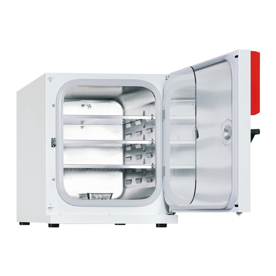
Page 15: Unit Overview
Unit overview (10) Figure 7: CO incubator C 150 (door hinged right) Triangle instrument panel with RP1 controller for temperature and CO and main power switch (2) Gas mixing head CO sensor Pt 100 temperature sensor Shelves Lower housing cover Silicone measuring port Inner glass door (10) Water pan... -
Page 16: Connection Panel At The Rear Of The Unit
2.3 Connection panel at the rear of the unit (11) (12) (13) (14) (15) Figure 8: Rear connection panel C 150 (11) Power cable (12) Miniature fuse (13) Connection socket for zero-voltage relay alarm contact (14) Quick acting closure socket for CO gas bottle (15) Ethernet interface for computer communication (option) Triangle instrument panel C 150... -
Page 17: Unit Doors
Second-hand units are units that were used for a short time for tests or exhibitions. They are thoroughly tested before resale. BINDER ensures that the chamber is technically sound and will work flawlessly. Second-hand units are marked with a sticker on the unit door. Please remove the sticker before commis- sioning the unit. -
Page 18: Guidelines For Safe Lifting And Transportation
Figure 10: Lift the unit with the aid of 4 people • Permissible ambient temperature range for transport: -10 °C / 14°F to +60 °C / 140°F. You can order transport packing and rolling pallets for transportation purposes from BINDER Service. C 150 (E2) 06/2011... -
Page 19: Storage
Storage Intermediate storage of the unit is possible in a closed and dry room. Observe the guidelines for tempo- rary decommissioning (chap. 17.2). • Permissible ambient temperature range for storage: -10 °C / 14°F to +60 °C / 140°F. • Permissible ambient humidity: max. 70% r.H., non-condensing When after storage in a cold location you transfer the unit to its warmer installation site, condensation may form in the inner chamber, on the housing or in the sensor compartment of the CO measurement. -
Page 20: Installation And Connections
Do not install or operate the CO incubator C 150 in potentially explosive areas. DANGER Explosion hazard. Danger of death. ∅ Do NOT operate the unit in potentially explosive areas. ∅ KEEP explosive dust or air-solvent mixtures AWAY from the vicinity of the unit. is harmful in high concentrations. -
Page 21: Co 2 Sensor
sensor Connect or remove the CO sensor without rotating and only when the incubator is turned off. Remove the CO sensor before removing or replacing its filter cap. The Teflon filter of the CO sensor prevents dirt and humidity from intruding into the measuring cell. It is available as a spare part. Replace it whenever it is damaged or soiled. -
Page 22: Water Pan
Water pan The water pan permits high humidity without condensation on the inner walls of the incubator. Place the positioning frame on the two marks at the bot- tom of the inner chamber. Then put the water pan in the positioning frame. Make sure that the water pan has firm contact with the inner chamber bottom and rests... -
Page 23: Connecting The Hose Lead To The Gas Bottle
Only use the supplied hose nozzle to connect to the quick acting closure socket. Otherwise, the quick acting closure socket may leak, and/or it may become impossible to con- nect the original hose nozzle. In this case, please contact BINDER Service. C 150 (E2) 06/2011... -
Page 24: Gas Bottle Connection Kit (Option)
Remove the rubber cover (b) by pulling it off. Unit rear Figure 15: Connection of the hose lead to the gas bottle Now fit the hose nozzle (c) in the quick acting closure socket. To remove the connection, pull the hose nozzle off the quick acting closure socket. -
Page 25: Electrical Connection
A gas supply pressure above 2.5 bar / 36 psi will result in unit damage. It is thus important to check the real output pressure of gas bottles, sets of gas bottles or central gas supplies before connecting the gas hose to the incubator. -
Page 26: Start Up
Start up After connecting the supply lines, turn on the unit by the main power switch (2). After turning on the incubator for the first time, enter the altitude of the site above sea level into the con- troller RP1 (chap. 8.1). Warming chambers may release odors in the first few days after commissioning. -
Page 27: Preset Factory Parameters
C 150 was last used for, for hygiene purposes you should clean and disinfect or sterilize the interior (chap. 15). WARNING: If customer should use a BINDER chamber running in non-supervised continu- ous operation, we strongly recommend in case of inclusion of irrecoverable specimen or samples to split such specimen or samples and store them in at least two chambers, if this is feasible. -
Page 28: Controller Rp1 Operating Modes
Open the CO supply's pressure reducer valve and set a CO primary pressure of 2.0 bar / 29 psi. Set the main power switch (2) to position I. The pilot lamp shows the unit is ready for operation. There is a subsequent brief startup phase in which the display items at the edges of the upper controller display light up successively. -
Page 29: Selecting And Setting The Operating Functions
Selecting and setting the operating functions The controller's lower display always shows the operating function (e.g. “SP” = temperature set point) and the upper display shows the associated value (e.g. 37.0). When the value in the upper display shows the temperature in °C or a CO concentration in % CO , the corresponding yellow LED to the right of the display will light up. - Page 30 Operating functions that can be set in operating mode HAND Display Setting range Operating function Temperature set point 0.0 °C to 50.0 °C Must be at least 7 °C / 12.6°F above the ambient temperature in order to ensure a stable temperature inside the C 150. set point 0.0 vol.-% to 20.0 Common value: 5.0 vol.-% (factory setting), or depending on the NaHCO...
-
Page 31: Operating Mode User: Advanced Settings
Operating mode USER: Advanced settings • In Normal display, press “MODE” and “EXIT” simultaneously for 3 seconds to access the options for selecting the C 150's operating modes. Figure 21: Selecting the operating mode • Press “▲”until the value “OP.U” (operating mode USER) appears in the upper display. •... - Page 32 Operating functions in operating mode USER Display Setting range Operating function Temperature set point 0.0 °C to 50.0 °C Must be at least 7 °C / 12.6 °F above the ambient temperature in order to ensure a stable temperature inside the C 150. set point 0.0 vol.-% to 20.0 Common value: 5.0 vol.-% (factory setting), or depending on the NaHCO...
- Page 33 Display Setting range Operating function Safety controller set point when set point type is “Limit” (Lit) Limit value, i.e., maximum permitted absolute temperature value. When 0.0 °C to 60.0 °C exceeded, the safety controller triggers an alarm. For technical reasons, the limit value should exceed the temperature set point by at least 2 °C.
- Page 34 Display Setting range Operating function Firmware revision of safety controller for service / maintenance pur- poses. Data record (year) for service / maintenance purposes. Data record (month) for service / maintenance purposes. Data record (day) for service / maintenance purposes. Data set version for service / maintenance purposes.
-
Page 35: Operating Mode Lock: Locking/Unlocking Of The Operating Functions' Settings By Operating Mode Hand
Operating mode LOCK: Locking/unlocking of the operating functions’ set- tings by operating mode HAND To avoid operating functions being changed by unauthorized persons, you can lock the operating func- tions’ settings. • In operating mode HAND, define a 3-digit numeric password in operating function “PA.H”. Locking the operating functions of operating mode HAND: •... -
Page 36: Performance During And After Power Failures And Shut Down
• Enter the password using the “▲” and “▼”buttons. • Confirm the entry with “MODE”. The controller returns to Normal display. If you have selected any password other than zero, operating mode HAND is temporarily unlocked. Changing the operating functions in operating mode HAND is now possible until a period of 30 sec. has passed with no activity. - Page 37 Toggle to operating mode USER Operating mode HAND Operating mode USER If operating mode HAND appears, toggle to operating mode USER with the arrow keys. Password request Password entry (factory setting: “1”). Entry of altitude Entry of the current altitude [km] above sea level with arrow keys. After 30 seconds the controller reverts to Normal Display automatically.
-
Page 38: Entering The Set Points Of Temperature And Co
Entering the set points of temperature and CO Normal Display Entry of temperature set point Entry of temperature set point with arrow keys. Entry of CO set point Entry of CO set point with arrow keys. After 30 seconds the controller reverts to Normal Display automatically. When setting a lower temperature set point, in order to save time, we recommend cooling down the unit by turning it off and opening both doors of the unit. -
Page 39: Temperature Safety Devices
If one of the over temperature protective devices permanently turns off the unit, the user cannot restart the device again. The protective cut-off devices are located internally. Only a service specialist can re- place them. Therefore, please contact an authorized service provider or BINDER Service. Safety controller (temperature safety device class 3.1) The incubator is equipped with an over temperature safety device class 3.1 acc. - Page 40 Normal Display simultaneously for 3 seconds Toggle to operating mode USER Operating mode HAND Operating mode USER If operating mode HAND appears, toggle to operating mode USER with the arrow keys. Password request Password entry (factory setting: “1”). 12 x Selecting the set point type Selecting set point type “Limit”...
-
Page 41: Setting The Safety Controller Set Point
Select the desired set point type. After 30 seconds the controller reverts to Normal Display automatically. 9.2.2 Setting the safety controller set point You can check and set the safety controller set point in operating modes HAND (chap. 7.2) or USER (chap. - Page 42 Password request Password entry (factory setting: “1”). 10 x Depending on the selected set point type (chap. 9.2.1) a different display appears: Entry of limit value or offset value With set point type Offset: With set point type Limit: Enter a limit value Enter an offset value Entry of limit value using the arrow keys.
-
Page 43: Alarm Functions
Alarm functions 10.1 Alarm functions overview When operational faults occur, the controller triggers visual and audible alarm signals. The LED “ALARM” always flashes when an alarm signal is emitted. A zero-voltage relay alarm output (13) (chap. 10.3) permits transmission of the alarm e.g., to a central monitoring system. -
Page 44: Zero-Voltage Relay Alarm Output
10.3 Zero-voltage relay alarm output Collective alarm output via the zero-voltage relay alarm contact The CO incubator is equipped at the rear with a zero-voltage relay output (13) for the temperature and , which permits the transmission of alarms to an external monitoring system in order to monitor and record the alarm signals. -
Page 45: Safety Controller Temperature Alarm
C 150 has cooled down. • If points 1 to 4 do not reveal the source of the fault, it may be that the unit is faulty. Please contact BINDER Service. 10.5 Temperature tolerance range alarm (high and low temperature) Main controller temperature alarm: The temperature has risen above or fallen below the temperature alarm threshold. -
Page 46: Door Open
Turn on the unit again. You can restart normal operation as soon as the requested values have equilibrated. If the same alarm recurs, please contact BINDER Service. 10.6 Door open The open and closed position of the unit door is controlled via the door contact switch. If the door is open, the temperature and CO controls turn off. -
Page 47: Co Tolerance Range Alarm (Co Over/Under Concentration)
• Open both unit doors for approx. 30 seconds. • Normal operation can be restarted, as soon as the requested values have been readjusted. If the same alarm recurs, please contact BINDER Service. 10.8 CO pressure too low The CO primary pressure at the intake valve is less than 0.3 bar / 4.4 psi below the ambient air pressure. -
Page 48: Temperature Sensor Failure
• Switching the zero-voltage relay alarm output Actions: • Turn off the C 150. • If necessary, clean and disinfect the C 150. Automatic sterilization is not possible with this fault. • Please contact BINDER Service. C 150 (E2) 06/2011 page 48/78... -
Page 49: Failure Of Co Sensor
• Replace the power plug. • Turn the C 150 on with the main power switch. • If the fault shows again, the unit could be faulty. Please contact BINDER Service. Repair must only be performed by qualified service personnel authorized by BINDER. -
Page 50: Reference Measurements
You need only use an accurate pH indicator or a pH-measuring electrode, which are standard equipment in cell culture laboratories. This method is not suitable for calibrating the BINDER FPI sensor system. This method is based on the acid base equilibrium of the buffer system in the culture media. -
Page 51: Measuring Co Directly Via Chemical Indicator Tubes
All the necessary equipment must be supplied by one manufacturer only and in a defined test system. Note: These test systems are not very accurate. A typical accuracy is around 10% of the full-scale value. These test systems are not suitable for calibrating the BINDER FPI sensor system. Figure 28: Example of chemical indicator... -
Page 52: Temperature Reference Measurement
CO incubators. The CTM 01 is suitable both for reference measurements in certified laboratories, and for service purposes. Please contact the BINDER INDIVIDUAL team. 12.2 Temperature reference measurement When performing a temperature reference measurement using an electronic measuring, and temperature display device, it is important to use a device traceable to an acknowledged standards/calibration institu- tion (DKD, PTB for Germany) with valid calibration certificate. -
Page 53: Base On Castors (Option)
This could happen e.g. while opening or closing the door, cleaning, loading and unloading the unit. BINDER offers a stacking adapter for direct thermal de- coupled stacking of two incubators. -
Page 54: Avoiding Microbial Contamination
Avoiding microbial contamination The main types of microbial contaminants in cell and tissue culture are bacteria, fungi, yeast, my- coplasma, and viruses. This chapter gives an overview of potential sources of contamination and precau- tions and measures to eliminate them. 14.1 Cells and media •... -
Page 55: Chamber Design And Equipment Of The Co Incubator C 150
• Condensation in the inner chamber represents a particular risk of contamination. The humidifying system with water pan with integrated condensation point developed by BINDER is an effective and easy way to ensure high humidity (95 ± 2% r.H.) inside the incubator without any condensation forming on the inner surfaces. -
Page 56: Handling The Co Incubator C 150
14.5 Handling the CO incubator C 150 Any manipulation of the CO incubator involves some contamination risks, from installation to opening of the doors and regular cleaning. Installation away from sources of contamination • Do not place the CO incubator on the floor or close to windows and doors. Use the optional stand, if appropriate. -
Page 57: Cleaning, Decontamination / Disinfection, And Sterilization
Cleaning, decontamination / disinfection, and sterilization DANGER Electrical hazard. Danger of death. ∅ Do NOT spill water or cleaning agents over the inner and outer surfaces. Disconnect the unit before cleaning. Disconnect the power plug. Completely dry the appliance before turning it on again. 15.1 Cleaning Disconnect the CO incubator from the power supply before cleaning. -
Page 58: Decontamination / Chemical Disinfection
For chemical disinfection, we recommend the disinfectant spray Art. No. 1002-0022. Any corrosive damage that may arise following use of other cleaning agents is excluded from liability by BINDER GmbH. 15.2 Decontamination / chemical disinfection Disconnect the CO incubator from the power supply prior to decontamination / disinfection. -
Page 59: Disinfection Of The Co
15.3 Disinfection of the CO sensor To ensure complete disinfection and proper function of the sensor, BINDER recommends a wipe disinfec- tion of the sensor head with pure alcohol or non-corrosive alcohol-based surface disinfectants. The disin- fectant must be non-corrosive and free of chlorine or any acid. We recommend using the disinfectant Art. - Page 60 • Sterilization phase: The temperature is maintained for 3 hours, which ensures that 180 °C / 356 °F is reached on all internal surfaces for at least 30 minutes. • A cooling-down phase follows until 37 °C / 98.6 °F is reached. The precise duration of the entire sterilization cycle depends on the ambient temperature at the installa- tion site and can thus vary.
- Page 61 • Activate the sterilization procedure: Press the controller button “180 °C” for 3 seconds to access the sterilization program. Figure 32: Initial sterilization display No sterilization can be started if the CO sensor is still plugged-in. You cannot start the sterilization if the operating mode HAND is locked.
-
Page 62: Aborting The Hot-Air Sterilization
CAUTION The glass door and inner chamber become hot during sterilization. Danger of burning. ∅ Do NOT touch the glass door and inner surfaces during sterilization. CAUTION Interruption of the temperature reaction time. Ineffective sterilization. ∅ Do NOT open the unit doors during sterilization. •... -
Page 63: Aborting The Hot-Air Sterilization Manually
CAUTION Glass door and inner chamber become hot during sterilization. Danger of burning. ∅ Do NOT touch the glass door and inner surfaces for approx. 4 hours after aborting ster- ilization. Aborting sterilization after less than 6 hours When aborting the sterilization prematurely, it may be that the cells/pathogens inside the unit have not all been killed. -
Page 64: Aborting The Hot-Air Sterilization By Opening The Outer Door
• After a manual abortion, the C 150 reverts to its standard operational status. The indication “ - - - “ in the lower display shows that the CO sensor is disconnected. As long as the interior temperature remains above the temperature set to trigger the temperature alarm, the C 150 will trigger alarm signals. -
Page 65: Maintenance, And Service
Service personnel authorized by BINDER will check this filter for pollution at each maintenance interval and replace it, if appropriate, but at least once a year. -
Page 66: Sending The Unit Back To Binder Gmbh
16.4 Sending the unit back to BINDER GmbH If you return a BINDER product to us for repair or any other reason, we will only accept the product upon presentation of an authorization number that has previously been issued to you. An authorization number will be issued after receiving your complaint either in writing or by telephone prior to your sending the BINDER product back to us. -
Page 67: Packing Inside The Unit, Equipment
(Elektro- und Elektronikgerätegesetz, ElektroG) from 23 March 2005, BGBl. I p. 762 or contact BINDER service who will organize taking back and disposal of the unit according to the German national law for electrical and electronic equipment (Elektro- und Elektronik- gerätegesetz, ElektroG) from 23 March 2005, BGBl. -
Page 68: Disposal Of The Unit In The Member States Of The Ec Except For The Federal Republic Of Germany
Instruct BINDER Service to dispose of the device. The general terms of payment and delivery of BINDER GmbH apply, which were valid at the time of purchasing the unit. Certified companies disassemble waste (used) BINDER equipment in primary substances for recycling according to directive 2002/96/EC. -
Page 69: Disposal Of The Unit In Non-Member States Of The Ec
If your distributor is not able to take back and dispose of the unit, please contact BINDER Service. Certified companies disassemble waste (used) BINDER equipment in primary substances for recycling according to directive 2002/96/EC. The devices must be free from toxic, infectious or radioactive sub- stances in order to eliminate any health hazards to the employees of the recycling companies. -
Page 70: Technical Description
December 1996 by TÜV CERT). All test equipment used is subject to the administration of measurement and test equipment that is also a constituent part of the BINDER QM DIN EN ISO 9001 systems. They are controlled and calibrated to a DKD-Standard at regular intervals. -
Page 71: C 150 Technical Data
18.4 C 150 technical data Exterior dimensions Width mm / inch 680 / 26.77 Height (incl. feet) mm / inch 819/ 32.24 Depth mm / inch 815 / 32.09 Depth plus door handle, I-triangle mm / inch 54 / 2.13 Depth plus power supply connection and gas connec- mm / inch 60 / 2.36... -
Page 72: Important Conversion Data For Non-Si Units
77°F and a power supply voltage fluctuation of ±10. The temperature data is determined in accordance to BINDER factory standard following DIN 12880, observing the recommended wall clearances of 10% of the height, width and depth of the inner chamber. -
Page 73: Equipment And Options C 150
18.7 Equipment and options C 150 To operate the CO incubator, use only original BINDER accessories or accessories / compo- nents from third-party suppliers authorized by BINDER. The user is responsible for any risk arising from using unauthorized accessories. Regular equipment... -
Page 74: Accessories And Spare Parts
18.8 Accessories and spare parts BINDER GmbH is responsible for the safety features of the unit only, provided skilled electri- cians or qualified personnel authorized by BINDER perform all maintenance and repair, and if components relating to chamber safety are replaced in the event of failure with original spare parts. -
Page 75: Dimensions C 150
18.9 Dimensions C 150 C 150 (E2) 06/2011 page 75/78... -
Page 76: Contamination Clearance Certificate
Contamination clearance certificate Unbedenklichkeitsbescheinigung Declaration regarding safety and health Erklärung zur Sicherheit and gesundheitlichen Unbedenklichkeit The German Ordinance on Hazardous Substances (GefStofV), and the regulations regarding safety at the workplace require that this form be filled out for all products that are returned to us, so that the safety and the health of our employees can be guaranteed. - Page 77 Kind of transport / transporter / Transportweg/Spediteur: Transport by (means and name of transport company, etc.) Versendung durch (Name Spediteur o.ä.) __________________________________________________________________________________ Date of dispatch to BINDER GmbH / Tag der Absendung an BINDER GmbH ___________________________________________________________________________________ C 150 (E2) 06/2011 page 77/78...
- Page 78 We are aware that, in accordance with Article 823 of the German Civil Code (BGB), we are directly liable with regard to third parties, in this instance especially the employees of BINDER GmbH, who have been entrusted with the handling / repair of the unit / component. / Es ist uns bekannt, dass wir gegenüber Dritten –...
Need help?
Do you have a question about the APT.line C 150 and is the answer not in the manual?
Questions and answers