Table of Contents
Advertisement
Quick Links
Operating Manual
Translation of the original operating manual
BD / BD-UL (E2) – Incubators with natural convection
ED / ED-UL (E2) – Drying and heating ovens with natural convection
FD / FD-UL (E2) – Drying and heating ovens with forced convection
with microprocessor temperature controller
Model
Model version
BD 23
BD023-230V
BD 23-UL
BD023UL-120V
BD 400
BD400-230V
BD 400-UL
BD400UL-120V
ED023-230V
ED 23
ED023UL-120V
ED 23-UL
ED 400
ED400-230V
ED 400-UL
ED400UL-208V
FD 23
FD023-230V
FD 23-UL
FD023UL-120V
BINDER GmbH
Address: Post office box 102, 78502 Tuttlingen, Germany Phone: +49 7462 2005 0
Fax: +49 7462 2005 100 Internet: http://www.binder-world.com
E-mail: info@binder-world.com Service Hotline: +49 7462 2005 555
Service Fax: +49 7462 2005 93 555 Service E-Mail: customerservice@binder-world.com
Service Hotline USA: +1 866 885 9794 or +1 631 224 4340 x3
Service Hotline Asia Pacific: +852 390 705 04 or +852 390 705 03
Service Hotline Russia and CIS: +7 495 988 15 16
Issue 01/2022
Art. No.
9010-0187, 9110-0187
9010-0189, 9110-0189
9010-0073, 9110-0073
9010-0176, 9110-0176
9010-0190, 9110-0190
9010-0191, 9110-0191
9010-0192, 9110-0192
9010-0193, 9110-0193
9010-0075, 9110-0075
9010-0168, 9110-0168
9010-0194, 9110-0194
9010-0196, 9110-0196
Art. No. 7001-0026
Advertisement
Table of Contents
Troubleshooting

Subscribe to Our Youtube Channel
Related Manuals for Binder BD 23


Summary of Contents for Binder BD 23
- Page 1 Fax: +49 7462 2005 100 Internet: http://www.binder-world.com E-mail: info@binder-world.com Service Hotline: +49 7462 2005 555 Service Fax: +49 7462 2005 93 555 Service E-Mail: customerservice@binder-world.com Service Hotline USA: +1 866 885 9794 or +1 631 224 4340 x3 ...
-
Page 2: Table Of Contents
Content SAFETY ........................4 Personnel Qualification ........................4 Operating manual ..........................4 Legal considerations ........................... 4 1.3.1 Intellectual property ........................5 Structure of the safety instructions ...................... 5 1.4.1 Signal word panel .......................... 5 1.4.2 Safety alert symbol ........................6 1.4.3 Pictograms ............................. - Page 3 10.1 General information, personnel qualification..................36 10.2 Maintenance intervals, service ......................36 10.3 Simple troubleshooting ........................37 10.4 Sending the chamber back to BINDER GmbH ................. 39 11. DISPOSAL......................39 11.1 Disposal of the transport packing ...................... 39 11.2 Decommissioning ..........................40 11.3 Disposal of the chamber in the Federal Republic of Germany ............
-
Page 4: Safety
Understanding and observing the instructions in this operating manual are prerequisites for hazard-free use and safety during operation and maintenance. In no event shall BINDER be held liable for any damages, direct or incidental arising out of or related to the use of this manual. -
Page 5: Intellectual Property
35 U.S.C. § 287(a). Products and services listed on the BINDER website may be sold individually or as part of a combination product. Additional patent applications may also be pending in the U.S. -
Page 6: Safety Alert Symbol
1.4.2 Safety alert symbol Use of the safety alert symbol indicates a risk of injury. Observe all measures that are marked with the safety alert symbol in order to avoid death or injury. 1.4.3 Pictograms Warning signs Explosive atmosphere Stability hazard Electrical hazard Hot surface Harmful substances... -
Page 7: Word Message Panel Structure
Figure 1: Position of labels on the chamber on the front (example: ED, FD) Keep safety labels complete and legible. Replace safety labels that are no longer legible. Contact BINDER Service for these replacements. BD / ED / FD (E2) 01/2022... -
Page 8: Type Plate
Serial No. 00000000000000 BINDER GmbH Im Mittleren Ösch 5 78532 Tuttlingen / Germany Made in Germany www.binder-world.com Figure 2: Type plate (example: BD 23 regular chamber) Indications of the type plate (example) Indication Information BINDER Manufacturer: BINDER GmbH BD 23... -
Page 9: General Safety Instructions On Installing And Operating The Chambers
(for Germany: DGUV guidelines 213-850 on safe working in laboratories, issued by the employers’ liability insurance association). BINDER GmbH is only responsible for the safety features of the chamber provided skilled electricians or qualified personnel authorized by BINDER perform all maintenance and repair, and if components relating to chamber safety are replaced in the event of failure with original spare parts. - Page 10 The chamber does not dispose of any measures of explosion protection. DANGER Danger of explosion due to introduction of flammable or explosive substances in the chamber. Serious injury or death from burns and / or explosion pressure. ∅ Do NOT introduce any substance into the chamber which is combustible or explosive at working temperature.
-
Page 11: Intended Use
The loading material shall not contain any corrosive ingredients that may damage the machine components. Such ingredients include in particular acids and halides. Any corrosive damage caused by such ingredients is excluded from liability by BINDER GmbH. The chamber does not dispose of any measures of explosion protection. -
Page 12: Foreseeable Misuse
The requirements described in the Operating Manual for installation site and ambient conditions (Chap. 3.4) must be met. WARNING: If customer should use a BINDER chamber running in non-supervised continuous operation, we strongly recommend in case of inclusion of irrecoverable specimen or samples to split such specimen or samples and store them in at least two chambers, if this is feasible. -
Page 13: Residual Risks
• Continued operation of the chamber during an obvious malfunction • Insertion of objects, particularly metallic objects, in louvers or other openings or slots on the chamber • Human error (e.g. insufficient experience, qualification, stress, exhaustion, laziness) To prevent these and other risks from incorrect operation, the operator shall issue operating instructions. Standard operating procedures (SOPs) are recommended. -
Page 14: Operating Instructions
• Absence of a plausibility check to rule out erroneous inscription of electrical components • Performance of repair work by untrained/insufficiently qualified personnel • Inappropriate repairs which do not meet the quality standard specified by BINDER • Use of replacement parts other than BINDER original replacement parts •... -
Page 15: Chamber Description
Edition, CSA C22.2 No. 1010.1-92, IEC 1010- 2-10. Chamber description BINDER incubators BD and drying and heating ovens ED and FD are equipped with an electronic PID- controller with digital display. The incubators BD indicate the temperature with an accuracy of a tenth of a degree. -
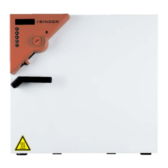
Page 16: Chamber Overview
Chamber overview Display Set-point value key Selector keys Time management key (10) Switch ON/OFF Lever for ventilation slide Safety device Door handle BD: ON/OFF switch for internal socket (option) ED / FD: Switch for interior lighting (option) or buzzer switch for audible over- temperature alarm (option) BD: Buzzer switch for audible (10) -
Page 17: Guidelines For Safe Lifting And Transportation
Note on second-hand chambers (Ex-Demo chambers): Second-hand chambers are chambers that have been used for a short time for tests or exhibitions. They are thoroughly tested before resale. BINDER ensures that the chamber is technically sound and will work flawlessly. -
Page 18: Location Of Installation And Ambient Conditions
Location of installation and ambient conditions Set up the chamber on an even and non-flammable surface, free from vibration and in a well-ventilated, dry location and align it using a spirit level. The site of installation must be capable of supporting the chamber’s weight (see technical data, chap. -
Page 19: Installation Of The Equipment
• Only use original connection cables from BINDER according to the above specification. UL chambers: Use only a UL Listed Power supply cord (UL category ELBZ), SJT 3x14 AWG (2.08 mm²);... -
Page 20: Connection To A Suction Plant (Optional)
• Prior to connection and start-up, check the power supply voltage. Compare the values to the specified data located on the chamber’s type plate (chamber front behind the door bottom left-hand, or on the left- hand side of the chamber, chap. 1.6). NOTICE Danger of incorrect power supply voltage due to improper connection. -
Page 21: Start Up
Start up Turning on the chamber Warming chambers may release odors in the first few days after commissioning. This is not a quality defect. To reduce odors quickly we recommend heating up the chamber to its nominal temperature for one day and in a well-ventilated location. 1. -
Page 22: Operating The Controller
Operating the controller Controller setting is identical with all three chambers BD, ED, and FD. The temperature controllers only differ in their temperature range (BD: up to 100 °C / 212 °F, ED/FD: up to 300 °C / 572 °F ) and the displayed accuracy (BD: a tenth of a degree, ED/FD: one degree). -
Page 23: Time Functions: Continuous Operation And Timer Operation
The display shows alternately “SP” and the previous temperature set-point (example: 60 °C): 3. With the buttons enter a set-point value between 0 and 300. The desired temperature set-point can be selected in a temperature range from 5 °C / 9 °F above room temperature up to 100 °C / 212 °F (BD) or 300 °C / 572 °F (ED/FD). -
Page 24: Switching Between "Continuous Operation" And "Timer Operation
6.3.1 Switching between “Continuous operation” and “Timer operation” Press the time management button The controller displays the actual time function. In time function “Continuous operation”, “t1” and “t inf” are displayed alternately. In time function “Timer operation”, “t1” is displayed alternately with the running-down time or “tOff”. -
Page 25: Timer Operation: Setting The Tempering Time
6.3.3 Timer operation: Setting the tempering time 1. Press the time management button . The controller indicates its current time function. 2. If necessary, switch to timer operation by button The display alternately shows”t1” and the running-down time or “tOff”: Remaining time (example: 28 minutes) –... -
Page 26: User Level Settings
User level settings By pressing down button in normal display (actual value display) for 5 sec, you enter the user menu. Settings in this menu affect controller operation. User level overview: Press down button for approx. 5 seconds Select the temperature unit (chap. 6.4.1) Press button Ramp function (chap. -
Page 27: Entering A Temperature Ramp
6.4.2 Entering a temperature ramp You can program temperature ramps in order to extend heating up times. This may be necessary in some cases to prevent temperature stresses in the material during the heating up phase. Temperature ramps should only be used if required. Using them may result in considerably slowing down the heating up times. The entry in °C/min or in °F/min means the nominal value gradient and limits the maximum temperature increase to this value. -
Page 28: General Notes
1. Press down button for approx. 5 seconds. The display alternately shows “unit” and the temperature unit: 2. Press again button The display alternately shows “rASd” and the set-point gradient: 3. Press again button The display alternately shows “Adr” and the actual setting of the chamber address: 4. -
Page 29: Temperature Safety Devices
Temperature safety devices Temperature safety device class 2 (DIN 12880) ED, FD The temperature safety device class 2 protects the chamber, its environment and the charging material from exceeding the maximum permissible temperature. Please observe the regulations applicable to your country (for Germany: DGUV guidelines 213-850 on safe working in laboratories, issued by the employers’... -
Page 30: Temperature Safety Device Class 3.1 (Din 12880) Bd (Option For Ed, Fd)
1. Turn the control knob (7) of the safety device using a coin to its end- stop (position 10) (chamber protection). 2. When the set point is reached, turn back the control knob (7) until its trip point (turn it counter-clockwise). 3. - Page 31 Function: The temperature safety device is functionally and electrically independent of the temperature control system and if an error occurs it performs a regulatory function. If you turn the control knob (7) to its end-stop (position 10), the safety device class 3.1 protects the chamber. If you set it to a temperature a little above the controller’s set-point temperature, it protects the charging material.
-
Page 32: Options
The chamber is regularly (BD) or optionally (ED) equipped with a serial interface RS 422 that can connect the BINDER APT-COM™ 4 Multi Management Software. The connection to a computer is established using the chamber’s interface via an interface converter RS 422 / RS 232. -
Page 33: Analog Output For Temperature (Option)
Analog output for temperature (option) With this option the chamber is equipped with an analog output 4-20 mA for temperature. This output permits transmitting data to external data registration systems or devices. The connection is carried out as a DIN socket at the rear of the chamber as follows: ANALOG OUTPUT 4-20 mA DC PIN 1: Temperature –... - Page 34 Do not use cleaning agents that may cause a hazard due to reaction with components of the device or the charging material. If there is doubt regarding the suitability of cleaning products, please contact BINDER service. We recommend using the neutral cleaning agent Art. No. Art. Nr. 1002-0016 for a thorough cleaning.
-
Page 35: Decontamination / Chemical Disinfection
For chemical disinfection, we recommend using the disinfectant spray Art. No. 1002-0022. Any corrosive damage that may arise following use of other disinfectants is excluded from liability by BINDER GmbH. With every decontamination / disinfection method, always use adequate personal safety controls. -
Page 36: Maintenance And Service, Troubleshooting, Repair, Testing
For personnel requirements please refer to the Service Manual. • Repair Repair of the chamber can be performed by BINDER Service or by BINDER qualified service partners or technicians, in accordance with the description in the Service Manual. After maintenance, the chamber must be tested prior to resuming operation. -
Page 37: Simple Troubleshooting
If there are is a technical fault or shortcoming, take the chamber out of operation and inform BINDER Service. If you are not sure whether there is a technical fault, proceed according to the following list. If you cannot clearly identify an error or there is a technical fault, please contact BINDER Service. - Page 38 Repeat entries, enter the values Display from any level. than approx. 30 sec. rapidly. Only qualified service personnel authorized by BINDER must perform repair. Repaired chambers must comply with the BINDER quality standards. BD / ED / FD (E2) 01/2022 page 38/66...
-
Page 39: Sending The Chamber Back To Binder Gmbh
10.4 Sending the chamber back to BINDER GmbH If you return a BINDER product to us for repair or any other reason, we will only accept the product upon presentation of an authorization number (RMA number) that has previously been issued to you. An authorization number will be issued after receiving your complaint either in writing or by telephone prior to your sending the BINDER product back to us. -
Page 40: Decommissioning
(Elektro- und Elektronikgerätegesetz, ElektroG from 20 October 2015, BGBl. I p. 1739) or contact BINDER service who will organize taking back and disposal of the chamber according to the German national law for electrical and electronic equipment (Elektro- und Elektronikgerätegesetz, ElektroG from 20 October 2015, BGBl. -
Page 41: Disposal Of The Chamber In The Member States Of The Eu Except For The Federal Republic Of Germany
According to Annex I of Directive 2012/19/EU of the European Parliament and of the Council on waste electrical and electronic equipment (WEEE), BINDER devices are classified as “monitoring and control instruments” (category 9) only intended for professional use“. They must not be disposed of at public collecting points. -
Page 42: Disposal Of The Chamber In Non-Member States Of The Eu
Danger of violation against existing law if not disposed of properly. Failure to comply with applicable law. Alteration of the environment. For final decommissioning and disposal of the chamber, please contact BINDER service. Follow the statutory regulations for appropriate, environmentally friendly disposal. -
Page 43: Technical Description
December 1996 by TÜV CERT). All test equipment used is subject to the administration of measurement and test equipment that is also constituent part of the BINDER QM DIN EN ISO 9001 systems. They are controlled and calibrated to a DKD-Standard at regular intervals. -
Page 44: Bd Technical Data
12.4 BD technical data Chamber size BD 23 BD 400 Exterior dimensions Width, net mm / inch 435 / 17.13 1235 / 48.62 Height, gross (incl. feet/castors) mm / inch 495 / 19.49 1025 / 40.35 Depth mm / inch 520 / 20.47... -
Page 45: Ed Technical Data
+22 °C +/- 3 °C / 71.6 °F +/- 5.4 °F and a power supply voltage fluctuation of +/-10. Technical data is determined in accordance to BINDER Factory Standard Part 1:2015 following DIN 12880:2007. All indications are average values, typical for units produced in series. We reserve the right to change technical specifications at any time. - Page 46 +22 °C +/- 3 °C / 71.6 °F +/- 5.4 °F and a power supply voltage fluctuation of +/-10. Technical data is determined in accordance to BINDER Factory Standard Part 1:2015 following DIN 12880:2007. BD / ED / FD (E2) 01/2022...
-
Page 47: Fd Technical Data
All indications are average values, typical for units produced in series. We reserve the right to change technical specifications at any time. If the chamber is fully loaded, the specified heating up times may vary according to the load. 12.6 FD 23 technical data Exterior dimensions Width, net mm / inch... - Page 48 +22 °C ± 3 °C / 71.6 °F ± 5.4 °F and a power supply voltage fluctuation of +/-10. Technical data is determined in accordance to BINDER Factory Standard Part 1:2015 following DIN 12880:2007. All indications are average values, typical for units produced in series. We reserve the right to change technical specifications at any time.
-
Page 49: Equipment And Options Bd (Extract)
12.7 Equipment and options BD (extract) To operate the chamber, use only original BINDER accessories or accessories / components from third-party suppliers authorized by BINDER. The user is responsible for any risk arising from using unauthorized accessories. Standard equipment Microprocessor temperature controller with LED display, timer function, and ramp function Temperature safety device class 3.1 acc. -
Page 50: Equipment And Options Ed (Extract)
12.8 Equipment and options ED (extract) To operate the chamber, use only original BINDER accessories or accessories / components from third-party suppliers authorized by BINDER. The user is responsible for any risk arising from using unauthorized accessories. Standard equipment Microprocessor temperature controller with LED display, timer function, and ramp function Temperature safety device class 2 acc. -
Page 51: Equipment And Options Fd (Extract)
12.9 Equipment and options FD (extract) To operate the chamber, use only original BINDER accessories or accessories / components from third-party suppliers authorized by BINDER. The user is responsible for any risk arising from using unauthorized accessories. Standard equipment Microprocessor temperature controller with LED display, timer function, and ramp function Temperature safety device cl. -
Page 52: Accessories And Spare Parts (Extract)
12.10 Accessories and spare parts (extract) BINDER GmbH is responsible for the safety features of the chamber only, provided skilled electricians or qualified personnel authorized by BINDER perform all maintenance and repair, and if components relating to chamber safety are replaced in the event of failure with original spare parts. -
Page 53: Certificates And Declarations Of Conformity
Certificates and declarations of conformity 13.1 EU Declaration of Conformity for BD BD / ED / FD (E2) 01/2022 page 53/66... - Page 54 BD / ED / FD (E2) 01/2022 page 54/66...
-
Page 55: Eu Declaration Of Conformity For Ed
13.2 EU Declaration of Conformity for ED BD / ED / FD (E2) 01/2022 page 55/66... - Page 56 BD / ED / FD (E2) 01/2022 page 56/66...
-
Page 57: Eu Declaration Of Conformity For Fd
13.3 EU Declaration of Conformity for FD BD / ED / FD (E2) 01/2022 page 57/66... - Page 58 BD / ED / FD (E2) 01/2022 page 58/66...
-
Page 59: Certificate For The Gs Mark Of Conformity Of The "Deutsche Gesetzliche Unfallversicherung E.v." (German Social Accident Insurance) Dguv
13.4 Certificate for the GS mark of conformity of the “Deutsche Gesetzliche Unfallversicherung e.V.“ (German Social Accident Insurance) DGUV BD / ED / FD (E2) 01/2022 page 59/66... - Page 60 BD / ED / FD (E2) 01/2022 page 60/66...
-
Page 61: Contamination Clearance Certificate
Contamination clearance certificate 14.1 For chambers located outside the USA and Canada Declaration with regard to safety and health Erklärung zur Sicherheit and gesundheitlichen Unbedenklichkeit The German Ordinance on Hazardous Substances (GefStofV), and the regulations regarding safety at the workplace, require that this form be filled out for all products that are returned to us, so that the safety and health of our employees can be warranted. - Page 62 Kind of transport / transporter / Transportweg/Spediteur: Transport by (means and name of transport company, etc.) Versendung durch (Name Spediteur o.ä.) ___________________________________________________________________________________ Date of dispatch to BINDER GmbH / Tag der Absendung an BINDER GmbH: ___________________________________________________________________________________ BD / ED / FD (E2) 01/2022 page 62/66...
- Page 63 We herewith commit ourselves and guarantee that we will indemnify BINDER GmbH for all damages that are a consequence of incomplete or incorrect information provided by us, and that we will exempt BINDER GmbH from eventual damage claims by third parties./ Wir versichern, dass wir gegenüber BINDER für jeden...
-
Page 64: For Chambers Located In The Usa And Canada
Please complete this form and the Customer Decontamination Declaration (next 2 pages) and attach the required pictures. E-mail to: IDL_SalesOrderProcessing_USA@binder-world.com After we have received and reviewed the complete information we will decide on the issue of a RMA number. Please be aware that size specifications, voltage specifications as well as performance specifications are available on the internet at www.binder-world.us... - Page 65 Customer (End User) Decontamination Declaration Health and Hazard Safety declaration To protect the health of our employees and the safety at the workplace, we require that this form is completed by the user for all products and parts that are returned to us. (Distributors or Service Organizations cannot sign this form) NO RMA number will be issued without a completed form.
- Page 66 4.5 Shipping laws and regulations have not been violated. I hereby commit and guarantee that we will indemnify BINDER Inc for all damages that are a consequence of incomplete or incorrect information provided by us, and that we will indemnify and hold harmless BINDER Inc.
Need help?
Do you have a question about the BD 23 and is the answer not in the manual?
Questions and answers