Table of Contents
Advertisement
Quick Links
Operating Manual
Translation of the original operating manual
KT (E6.1)
Cooling Incubator
with Peltier Refrigerating Technology and program controller
Model
KT 53
KT 53-UL
KT 115
KT 115-UL
KT 170
KT 170-UL
BINDER GmbH
Address
Tel.
Fax
Internet
E-mail
Service Hotline
Service Fax
Service E-Mail
Service Hotline USA
Service Hotline Asia Pacific
Service Hotline Russia and CIS +7 495 98815 17
Issue 07/2015
Model version
KT053-230V
KT053UL-120V
KT115-230V
KT115UL-120V
KT170-230V
KT170UL-120V
Post office box 102
D-78502 Tuttlingen
+49 7462 2005 0
+49 7462 2005 100
http://www.binder-world.com
info@binder-world.com
+49 7462 2005 555
+49 7462 2005 93 555
service@binder-world.com
+1 866 885 9794 or +1 631 224 4340 x3
+852 39070500 or +852 39070503
Art. No.
9020-0311
9020-0312
9020-0313
9020-0314
9020-0289
9020-0310
Art. No. 7001-0291
Advertisement
Table of Contents

Related Manuals for Binder KT 53


Summary of Contents for Binder KT 53
- Page 1 Operating Manual Translation of the original operating manual KT (E6.1) Cooling Incubator with Peltier Refrigerating Technology and program controller Model Model version Art. No. KT 53 KT053-230V 9020-0311 KT 53-UL KT053UL-120V 9020-0312 KT 115 KT115-230V 9020-0313 KT 115-UL KT115UL-120V 9020-0314...
-
Page 2: Table Of Contents
Contents SAFETY ........................6 Legal considerations ........................... 6 Structure of the safety instructions ...................... 6 1.2.1 Signal word panel ........................6 1.2.2 Safety alert symbol ........................7 1.2.3 Pictograms ..........................7 1.2.4 Word message panel structure ....................8 Localization / position of safety labels on the unit ................8 Type plate ............................ - Page 3 TIME PROGRAMS ....................38 Starting and running an existing time program ................. 40 Cancelling a running time program ....................43 Creating a new time program ......................44 9.3.1 Section handling ........................46 9.3.2 Temperature setpoint ......................47 9.3.3 Section duration ........................47 9.3.4 Repeating one or several sections within a time program ............
- Page 4 20.2.1 Cleaning ..........................116 20.2.2 Decontamination ........................117 20.3 Sending the unit back to BINDER GmbH ..................118 21. DISPOSAL ......................119 21.1 Disposal of the transport packing ....................119 21.2 Decommissioning ..........................119 21.3 Disposal of the unit in the Federal Republic of Germany ............... 119 21.4 Disposal of the unit in the member states of the EC except for the Federal Republic of Germany 120...
- Page 5 24. CERTIFICATES ....................129 24.1 EC Declaration of Conformity......................129 25. PRODUCT REGISTRATION ................132 26. CONTAMINATION CLEARANCE CERTIFICATE ..........133 26.1 For units located outside North America and Central America ............133 26.2 For units in North America and Central America ................136 KT (E6.1) 07/2015 Page 5/138...
-
Page 6: Safety
Understanding and observing the instructions in this operating manual are prerequisites for hazard-free use and safety during operation and maintenance. In no event shall BINDER be held liable for any damages, direct or incidental arising out of or related to the use of this manual. -
Page 7: Safety Alert Symbol
WARNING Indicates a potentially hazardous situation which, if not avoided, could result in death or serious (irreversible) injury. CAUTION Indicates a potentially hazardous situation which, if not avoided, may result in moderate or minor (reversible) injury. CAUTION Indicates a potentially hazardous situation which, if not avoided, may result in damage to the product and/or its functions or of a property in its proximity. -
Page 8: Word Message Panel Structure
KT with optional interior socket: below • the interior socket Service label Figure 1: Position of labels on KT-UL Keep safety labels complete and legible. Replace safety labels that are no longer legible. Contact BINDER service for these replacements. KT (E6.1) 07/2015 Page 8/138... -
Page 9: Type Plate
78532 Tuttlingen / Germany www.binder-world.com Figure 2: Type plate (example of KT 170 regular unit) Indications of the type plate Information (example) BINDER Manufacturer: BINDER GmbH KT 170 Model Cooling incubator Device name Serial No. 00-00000 Serial no. of the unit... -
Page 10: General Safety Instructions On Installing And Operating The Cooling Incubator
(for Germany). BINDER GmbH is only responsible for the safety features of the unit provided skilled electricians or qualified personnel authorized by BINDER perform all maintenance and repair, and if components relating to chamber safety are replaced in the event of failure with original spare parts. - Page 11 Any solvent contained in the charging material must not be explosive or inflammable. I.e., irrespective of the solvent concentration in the steam room, NO explosive mixture with air must form. The temperature inside the chamber must lie below the flash point or below the sublimation point of the charging material. Familiarize yourself with the physical and chemical properties of the charging material, as well as the contained moisture constituent and its behavior with the addition of heat energy.
-
Page 12: Intended Use
Any corrosive damage caused by such ingredients is excluded from liability by BINDER GmbH. WARNING: If customer should use a BINDER chamber running in non-supervised continuous operation, we strongly recommend in case of inclusion of irrecoverable specimen or samples to split such specimen or samples and store them in at least two chambers, if this is feasible. -
Page 13: Measures To Prevent Accidents
Measures to prevent accidents The operator of the cooling incubator must observe the following rule: “Betreiben von Arbeitsmitteln. Betreiben von Kälteanlagen, Wärmepumpen und Kühleinrichtungen“ (Operation of work equipment. Operation of refrigeration systems, heat pumps and refrigeration equipment) (GUV-R 500 chap. 2.35) (for Germany). -
Page 14: Unit Description
Unit description A high level of precision, reliability, and safety for all growth parameters ensures optimum incubation conditions. Moreover, the KT cooling incubator is designed for maximum usability – even in continuous operation year after year. It fulfills all technical and application-specific requirements arising in experimentation such as in the areas of biotechnology, medicine, the nutrition industry, pharmaceutical and cosmetics industries, botany, and zoology. -
Page 15: Unit Overview
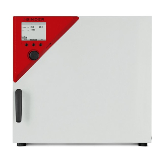
Unit overview Instrument panel with microprocessor controller T4.12 and USB interface Door handle Unit door Main power switch Figure 3: Cooling incubator KT (example: model KT 170) Instrument panel 5,7" controller display Context-sensitive buttons USB interface Operating button Pilot lamp: ready for operation Figure 4: Instrument panel with microprocessor controller T4.12 and USB interface KT (E6.1) 07/2015 Page 15/138... -
Page 16: Unit Rear
Unit rear Figure 5: Unit rear with position of options (example KT 170) DIN-socket for zero-voltage relay alarm outputs (option) (not used) DIN socket for analog output 4-20 mA (option) DIN-socket for zero-voltage relay control outputs (option) RS 422 interface for computer communication (option) Ethernet interface for computer communication Peltier fan grid Socket for IEC connector plug with power cable... -
Page 17: Completeness Of Delivery, Transportation, Storage, And Location Of Installation
Second-hand units are units that were used for a short time for tests or exhibitions. They are thoroughly tested before resale. BINDER ensures that the chamber is technically sound and will work flawlessly. Second-hand units are marked with a sticker on the unit door. Please remove the sticker before commissioning the unit. -
Page 18: Storage
Permissible ambient temperature range during transport: 10 °C / 14°F to +60 °C / 140°F. You can order transport packing for moving or shipping purposes from BINDER service. Storage Intermediate storage of the unit is possible in a closed and dry room. Observe the guidelines for temporary decommissioning (chap. - Page 19 Two devices up to size 115l can be piled on top of each other. For this purpose, place rubber pads under all four feet of the upper unit to prevent the device from slipping. CAUTION Sliding or tilting of the upper unit. Damage to the units.
-
Page 20: Installation Of The Equipment
Installation of the equipment Spacer for wall distance Please fix both spacers with the supplied screws at the unit rear. This serves to ensure the prescribed minimum distance to the rear wall of 100 mm / 3.94 in. Figure 6: Spacer for wall distance Figure 7: Rear KT 170 with mounted spacers KT (E6.1) 07/2015 Page 20/138... -
Page 21: Electrical Connection
The cooling incubators KT are supplied ready for connection. They come with an IEC connector plug. Nominal voltage ± 10% at the Current Model Power plug Unit fuse type indicated power frequency KT 53 200-230 V at 50 Hz KT 115 Shock-proof plug 10 A 200-230 V at 60 Hz KT 170 KT 53-UL... -
Page 22: Start Up
Behavior when opening the door When you open the door, heating and fan turn off. After a delay time of von 60 seconds (KT 53), 40 seconds (KT 115) or 20 seconds (KT 170) they turn on again. -
Page 23: Menu Structure
Menu structure Fixed value 08.03.2013 05:05:06 Setpoint Actual value 25.0 25.2 Temperature [°C] 100.0 Initial view (sample values). Press the desired menu button. User Quick menu Menu From the Initial view you have access to different menus using the menu buttons “User”, “Quick menu”, or “Menu”. - Page 24 Fixed value 08.03.2013 05:05:06 ..\ Menu Measurement chart Optional equipment Sensor adjustment General menu (next page) Service contact (“Optional equipment” menu item is visible only with System information optional unit equipment) Close Home Switching between the operating modes “control off” or “fixed value”, Controller mode chap.
-
Page 25: Quick Menu
6.1.2 Quick menu The Quick menu provides fast access to frequently used functions. Fixed value 08.03.2013 05:05:06 ..\ Quick menu Measurement chart Active alarms Temperature setpoint Fan speed setpoint “Quick menu” Safety controller setpoint Time program Week program Close Home Measurement chart Graphical display of the measured values, chap. -
Page 26: Operating Modes
Operating modes In the “control off” mode (chap. 6.2.1), the controller is non-functional and displays only the actual values. There is no heating or refrigeration. The temperature approximates the ambient value, the fan turns with 40 % speed. You can enter the desired set point values in “fixed value” mode (chap. 8). The controller then operates as a fixed-point control, i.e., it reaches and maintains the defined temperature set-point until the next manual change. - Page 27 Control off 08.03.2013 05:05:06 ..\ Menu Controller mode Event list Alarms General menu with controller mode “Control off”. Setpoints The controller mode “Fixed value” or “Control off” is Safety controller indicated in the display headline. Programs Import/Export Settings Close Home Go back to the initial view with “Home”.
-
Page 28: Performance During And After Power Failure
Performance during and after power failure During a power failure, all controller functions are shut down. The optional zero-voltage relay alarm output (chap. 19.4) is switched to alarm position for the whole duration of the power failure. After the power returns, all functions return to the same status the chamber had before power failure. . The controller continues to function in the original operating mode it was in previously before the power failure occurred. -
Page 29: Information
Date of production (YY/MM/DD): 2012/01/01 Parameter version: 511B-0006-0011 Firmware version (1): 521C-0001-002A Firmware version (2): 521B-0005-001E Close Home To display the BINDER Service contact data, go to Menu > Service contact Fixed value 08.03.2013 05:05:06 ..\ Service contact Service hotline Submenu “Service contact”. -
Page 30: Configuration Of Optional Equipment
Configuration of optional equipment The “Optional equipment” menu item is visible only with optional unit equipment. To access the selection menu, go to Menu > Optional equipment Fixed value 08.03.2013 05:05:06 ..\ Optional equipment Door heating Interior socket Zero-voltage relay control outputs Submenu “Optional equipment”. -
Page 31: Turning On / Off The Optional Interior Socket
Setting the offset value: Fixed value 08.03.2013 05:05:06 ..\ Door heating \ Offset Entry menu „Offset“. [°C] Select each number with the operating button and press the operating button to confirm. Setting range: 0 °C up to 5 °C. Press the “Ok” button to confirm. Ins Pos1 End Ok 1 2 3 4 5 6 7 8 9 , Close... -
Page 32: Switching On Or Off The Optional Zero-Voltage Relay Control Outputs
Switching on or off the optional zero-voltage relay control outputs For units equipped with zero-voltage relay outputs (option, chap. 19.6), you can switch on or off the output via the controller. To access the setting menu for the operating modes “Fixed value” and “Control off”, go to Menu >... -
Page 33: Switching On Or Off The Optional Object Temperature Display
Switching on or off the optional object temperature display For units equipped with the digital object temperature display with a flexible Pt 100 temperature sensor (option, chap. 19.4), you can switch on or off the object temperature indication via the controller. To access the setting menu, go to Menu >... -
Page 34: Set-Point Entry In "Fixed Value" Operating Mode
Set-point entry in “Fixed value” operating mode Setting ranges: Temperature 4 °C / 23 °F up to +100 °C / 212 °F Fan speed 40 % up to 100 % (full speed) with temperature values from 4 °C up to 70 °C With temperature values above 70 °C the effective fan speed is always 100 %. - Page 35 Temperature setting To enter the temperature setpoint, go to Quick menu > Temperature setpoint Fixed value 08.03.2013 05:05:06 ..\ Temperature setpoint Entry menu “Temperature setpoint”. [°C] Select each number with the operating button and press the operating button to confirm. Setting range: 4 °C / 23 °F up to +100 °C / 212 °F Press the “Ok”...
-
Page 36: Entering The Set-Points Via General Menu
Entering the set-points via general menu To enter set-points via general menu, go to Menu > Setpoints Fixed value 08.03.2013 05:05:06 ..\ Setpoints Temperature Fan speed Submenu “Setpoints”. Select “Temperature” or “Fan speed” and press the operating button. Close Home Temperature setting Menu >... - Page 37 Fan speed setting To enter the fan speed setpoint, go to Menu > Setpoints > Fan speed Fixed value 08.03.2013 05:05:06 ..\ Fan speed setpoint Entry menu “Fan speed setpoint”. Select each number with the operating button and press the operating button to confirm. Setting range: 40 % up to 100 % (effective with temperature values from 4 °C to 70 °C.
-
Page 38: Time Programs
Time programs The T4.12 program controller permits programming temperature cycles. It offers 52 program memory positions with up to 100 program sections each. To access the menu selection for time programs, select Menu > Programs > Time program Fixed value 08.03.2013 05:05:06 Setpoint Actual value... - Page 39 Fixed value 08.03.2013 05:05:06 ..\ Programs\Time programs Start Stop Pause Submenu “Time programs”. Resume Turn the operating button to see additional menu Edit items. Create Rename Delete Close Home Fixed value 08.03.2013 05:05:06 ..\ Programs\Time programs Delete all Submenu “Time programs” (next page) Close Home KT (E6.1) 07/2015...
-
Page 40: Starting And Running An Existing Time Program
Starting and running an existing time program To start a time program, go to Menu > Programs > Time program > Start. (You can also go to Quick menu > Time program > Start , see below). Starting is also possible directly from the program editor (chap. 9.3.9). In the “Control off”... - Page 41 Fixed value 08.03.2013 05:05:06 ..\ Start time (HH:MM:SS) Entry menu “Start time”. 5:05:36 The current time plus 30 seconds is shown. For a postponed start, enter the desired start time with the operating button. Press the “Ok” button to confirm. Ins Pos1 End 1 2 3 4 5 6 7 8 9 Close...
- Page 42 To start a time program, you can also go to Quick menu > Time program > Start Fixed value 08.03.2013 05:05:06 ..\ Quick menu Measurement chart Active Alarms Temperature setpoint “Quick menu”. Fan speed setpoint Select “Time program” Safety controller setpoint and press the operating button Time program Week program...
-
Page 43: Cancelling A Running Time Program
Performance after completing the program The controller automatically changes to the “Fixed value” operation mode. Before starting the program, check the temperature setpoint entered in the “Fixed value” operation mode. After end of the program, the temperature will equilibrate to this value. CAUTION Too high or too low temperature after the program ends. -
Page 44: Creating A New Time Program
Creating a new time program For each program section you can enter a temperature set-point, the fan speed, the section’s duration, the type of temperature transition “R” (ramp) or “S” (step) (see chap. 9.3.6), and the tolerance range. When changing the temperature set-point, check the setting of the safety controller (chap. 17) if the safety controller has been set to “limit”... - Page 45 If you selected “Based on”, then the program selection window appears: Fixed value 08.03.2013 05:05:06 ..\ Select program Program0001 Program0002 Program0003 Submenu “Select program” (example). Select the desired program and press the operating button. Close Home If no program has been created and saved so far, the message “No programs found” appears. Press the operating button to confirm with “Ok”...
-
Page 46: Section Handling
To create a second program line (section), turn the operating button to the right and press it. The next section will be added. Fixed value 08.03.2013 05:05:06 ..\ Temperature controller No. Value H:M:S Ref. Rep. T. min T.max R/S 25.00 00:00:15 -999.00 999.00 Ramp 25.00 00:00:15 -999.00 999.00 Ramp... -
Page 47: Temperature Setpoint
9.3.2 Temperature setpoint Fixed value 08.03.2013 05:05:06 Time program editor. ..\ Temperature controller [°C] Select a value under “Value” No. Value H:M:S Ref. Rep. T. min T.max and press the operating button. 25.00 00:00:15 -999.00 999.00 Ramp 08.03.2013 05:05:06 ..\ Temperature setpoint Entry menu “Temperature setpoint”. -
Page 48: Repeating One Or Several Sections Within A Time Program
9.3.4 Repeating one or several sections within a time program Enter the number of the target section, which shall be the start of the repeat cycle, under “Ref.” and the number of repeats under “Rep.”. To have sections repeated infinitely enter the number of cycles “Rep.” as “-1”. -
Page 49: Tolerance Range
The following example shows a time program where the sections 2 and 3 shall be repeated 30 times: Fixed value 08.03.2013 05:05:06 ..\ Temperature controller [°C] No. Value H:M:S Ref. Rep. T. min T.max 1 40.00 00:30:00 -999.00 999.00 Ramp 2 60.00 01:30:00 -999.00 999.00 Ramp 3 80.00 01:00:00... - Page 50 Continue to enter the maximum value: Fixed value 08.03.2013 05:05:06 Time program editor. ..\ Temperature controller [°C] Select a value under “T. max” No. Value H:M:S Ref. Rep. T. min T.max and press the operating button. 1 25.00 00:00:15 -999.00 999.00 Ramp Fixed value...
-
Page 51: Set-Point Ramp And Set-Point Step Modes
9.3.6 Set-point ramp and set-point step modes “Ramp” mode The set-point of a given program section functions as the section’s start temperature. During the section’s duration, the temperature set-point gradually passes to the set-point of the subsequent program section. The actual temperature value follows the continually changing set-point. If the last program section is in “ramp”... - Page 52 Examples: “Ramp” mode W/°C t/min. Corresponding program table: Value H:M:S Ref. Rep. T. min T.max 40.0 00:30:00 -999 +999 Ramp 60.0 01:30:00 Ramp 80.0 01:00:00 Ramp 80.0 03:20:00 -999 +999 Ramp 20.0 00:00:01 -999 +999 Ramp “Step” mode W/°C t/min. Corresponding program table Value H:M:S...
-
Page 53: Switching On Or Off The Optional Zero-Voltage Relay Outputs
9.3.7 Switching on or off the optional zero-voltage relay outputs For units equipped with zero-voltage relay outputs (option, chap. 19.6), you can switch on or off the outputs for each program section via the program editor. Fixed value 08.03.2013 05:05:06 Time program editor (with option relay outputs) ..\ Temperature controller [°C]... -
Page 54: Calling Up The Next Parameter
9.3.8 Calling up the next parameter Fixed value 08.03.2013 05:05:06 ..\ Temperature controller [°C] No. Value H:M:S Ref. Rep. T. min T.max 1 40.00 00:30:00 -999.00 999.00 Step 2 60.00 01:30:00 -5.00 5.00 Step 3 80.00 01:00:00 -5.00 5.00 Step Time program editor (example). - Page 55 Entering the set-point values for another parameter (fan speed) The number of program lines (program sections) equal to the number in the temperature program is displayed. The settings of section length, repeats and the selection „Ramp“ or „Step“ are taken over from the temperature program;...
-
Page 56: Saving The Time Program And Leaving The Program Editor
9.3.9 Saving the time program and leaving the program editor Fixed value 08.03.2013 05:05:06 ..\ Temperature controller [°C] No. Value H:M:S Ref. Rep. T. min T.max 1 40.00 00:30:00 -999.00 999.00 Step 2 60.00 01:30:00 -5.00 5.00 Step 3 80.00 01:00:00 -5.00 5.00 Step... - Page 57 With “Exit (without saving!)” you exit the program editor without saving the program. There is a security question first: Fixed value 08.03.2013 05:05:06 ..\ Confirm operation Do not exit Really exit (without saving!) Submenu “Confirm operation”. This a security question. Select the desired function and press the operating button.
-
Page 58: Program Interruption
Program interruption You can manually interrupt a time program (pause), or this will automatically occur when exceeding the entered tolerance range values of the corresponding program section (see chap. 9.3.5). Manual program interruption To interrupt a time program, go to Menu >... -
Page 59: Deleting A Time Program
Deleting a time program To delete a time program, go to Menu > Programs > Time program > Delete Menu > Programs > Time program > Delete all Fixed value 08.03.2013 05:05:06 ..\ Programs\Time program Start Stop Pause Submenu “Time program”. Resume Select “Delete”... -
Page 60: Week Programs
Week programs The T4.12 program controller permits programming week programs with real-time reference. It offers 8 week program places in total with up to 30 shift points for each week program. To access the menu selection for week programs, select Menu >... -
Page 61: Starting And Running An Existing Week Program
10.1 Starting and running an existing week program To start a week program, go to Menu > Programs > Week program > Start (You can also go to Quick menu > Week program > Start , see below). Starting is also possible directly from the program editor (chap. 10.3.8). In the “Control off”... - Page 62 Fixed value 08.03.2013 05:05:06 ..\ Start time (HH:MM:SS) Entry menu “Start time”. 5:05:36 The current time plus 30 seconds is shown. For a postponed start, enter the desired start time with the operating button. Press the “Ok” button to confirm. Ins Pos1 End 1 2 3 4 5 6 7 8 9 Close...
- Page 63 To start a week program, you can also go to Quick menu > Week program > Start Fixed value 08.03.2013 05:05:06 ..\ Quick menu Measurement chart Active Alarms Temperature setpoint Fan speed setpoint “Quick menu”. Safety controller setpoint Select “Week program” Time program and press the operating button Week program...
-
Page 64: Cancelling A Running Week Program
10.2 Cancelling a running week program To cancel a week program, go to Menu > Programs > Week program > Stop. To cancel a running week program, you can also go to Quick menu > Week program > Stop. The controller returns to the initial view. Performance after manual program stop The controller automatically changes to the “Fixed value”... -
Page 65: Creating A New Week Program
10.3 Creating a new week program A week program permits defining up to 30 sections for the whole week. These sections function as shift points. A shift-point is characterized by its time, temperature value, and state (active / inactive). With a running week program, the temperature of the currently active shift point is maintained until the moment of the next active shift point with its new temperature set-point. - Page 66 If you selected “Based on”, then the program selection window appears: Fixed value 08.03.2013 05:05:06 ..\ Select program Program0004 Program0005 Day-Night Submenu “Select program” (example). Select the desired program and press the operating button. Close Home If no program has been created and saved so far, the message “No programs found” appears. Press the operating button to confirm with “Ok”...
-
Page 67: Section Handling
To create a second program line (section), turn the operating button to the right and press it. The next section will be added. Fixed value 08.03.2013 05:05:06 ..\ Temperature controller [°C] Value H:M:S Activity 25.00 Monday 00:00:00 Inactive Week program editor 25.00 Monday 00:00:00... -
Page 68: Temperature Setpoint
10.3.2 Temperature setpoint Fixed value 08.03.2013 05:05:06 Week program editor. ..\ Temperature controller [°C] Select a value under “Value” Value H:M:S Activity and press the operating button. 25.00 Monday 00:00:00 Inactive Fixed value 08.03.2013 05:05:06 ..\ Temperature setpoint Entry menu “Temperature setpoint”. 5.00 [°C] A temperature value is shown. -
Page 69: Time Of The Day
Fixed value 08.03.2013 05:05:06 ..\ Day of week Mon-Fri Sun-Thu Mon-Sat Submenu “Settings” (next page). Fri+Sat Select the desired function Sat+Sun and press the operating button. Close 10.3.4 Time of the day Fixed value 08.03.2013 05:05:06 Week program editor. ..\ Temperature controller [°C] Select a value under “H:M:S”... -
Page 70: Activity Of The Shift-Point
10.3.5 Activity of the shift-point Fixed value 08.03.2013 05:05:06 Week program editor. ..\ Temperature controller [°C] Select a field under “Activity” Value H:M:S Activity and press the operating button. 25.00 Monday 00:00:00 Inactive Fixed value 08.03.2013 05:05:06 ..\ Activity Inactive Active Submenu “Activity“. -
Page 71: Calling Up The Next Parameter
10.3.7 Calling up the next parameter Fixed value 08.03.2013 05:05:06 ..\ Temperature controller Value H:M:S Activity 35.00 Monday 08:00:00 Active 40.00 Monday 10:00:00 Active 35.00 Monday 18:00:00 Active Week program editor (example). 10.00 Monday 20:00:00 Active Press the “Menu” button. 35.00 Tuesday 08:00:00... - Page 72 Entering the set-point values for another parameter (fan speed) The number of program lines (program sections) equal to the number in the temperature program is displayed. The settings of the shift points (day, time, activity) are taken over from the temperature program;...
-
Page 73: Saving The Week Program And Leaving The Program Editor
10.3.8 Saving the week program and leaving the program editor Fixed value 08.03.2013 05:05:06 ..\ Temperature setpoint [°C] Value H:M:S Activity 35.00 Monday 08:00:00 Active 40.00 Monday 10:00:00 Active 35.00 Monday 18:00:00 Active Week program editor (example). 10.00 Monday 20:00:00 Active Press the “Menu”... -
Page 74: Deleting A Week Program
With “Exit (without saving!)” you exit the program editor without saving the program. There is a security question first: Fixed value 08.03.2013 05:05:06 ..\ Confirm operation Do not exit Really exit (without saving!) Submenu “Confirm operation”. This a security question. Select the desired function and press the operating button. -
Page 75: Key Lock
Key lock The key lock function serves to block the access to the controller. When the “key lock” is activated, the controller remains in the actual view and can only be changed when entering the current password. To configure the key lock function, go to User >... -
Page 76: Directly Activating The Key Lock Function
11.1 Directly activating the key lock function To directly activate the key lock, go to User > Key lock > Key lock On Fixed value 08.03.2013 05:05:06 ..\ Key lock Key lock On Automatic key lock Password Submenu “Key lock”. Select “Key lock On”... - Page 77 Under “Waiting time [min]” you can enter the waiting time, after which the key lock will be automatically activated. This time starts running off after the last entry to the controller. To enter it, go to User > Key lock > Automatic key lock > Waiting time [min] Enter wait time [min] 08.03.2013 05:05:06 ..\ User\Waiting time...
-
Page 78: Changing The Password For Unlocking The Key Lock
This symbol on the controller display indicates that the “key lock” function is activated. 11.3 Changing the password for unlocking the key lock To change the password for unlocking the key lock, go to User > Key lock > Password Fixed value 08.03.2013 05:05:06 ..\ Key lock... -
Page 79: General Controller Settings
General controller settings In the "Settings" submenu, you can enter the date and time, select the language for the menus and the desired temperature unit, perform the configuration for the controller’s communication functions, and reset the controller to factory settings. To access the "Settings"... -
Page 80: Setup Wizard
12.1 Setup wizard The setup wizard will guide you sequentially through the important menus to configure your chamber • Menu language • Chamber name • Date and time • IP address • Subnet mask • Network name • Gateway • DNS 1 •... - Page 81 Function “Set date” Fixed value 08.03.2013 05:05:06 ..\ Select date (DD.MM.YYYY) 8.03.2013 Entry menu “Select date”. The current date is shown. If it is incorrect, enter the correct date with the operating button. Press the “Ok” button to confirm. Ins Pos1 End Ok 1 2 3 4 5 6 7 8 9 Close Home...
-
Page 82: Selecting The Menu Language Of The T4.12 Controller
12.3 Selecting the menu language of the T4.12 controller The T4.12 chamber controller communicates via a comprehensible menu navigation in plain text in a selectable language. To select the desired menu language, go to Menu > Settings > Sprache, Language, Langue, Idioma, Lingua Fixed value 08.03.2013 05:05:06 ..\ Sprache, Language, Langue, Idioma, Lingua... -
Page 83: Changing The Temperature Unit
12.5 Changing the temperature unit To select the temperature unit, go to Menu > Settings > Temperature unit Fixed value 08.03.2013 05:05:06 ..\ Temperature unit Celsius [°C] Fahrenheit [°F] Kelvin [K] Submenu “Temperature unit”. Select the desired temperature unit” and press the operating button. Close Home If you selected the temperature unit, the controller returns to the „Settings“... -
Page 84: Factory Reset
The settings of this submenu are required for networking chambers with an Ethernet interface, e.g. to connect them with BINDER’s communication software APT-COM™ 3 DataControlSystem. You can display the chamber‘s IP address that has been assigned by your DHCP server or manually assign the IP address. - Page 85 Fixed value 08.03.2013 05:05:06 ..\ Network settings DNS1 DNS2 Submenu “Network settings” (next page). Close Home Show network settings Overview of the entire network configuration DHCP on/off Switching on and off the DHCP state IP address Entering the desired IP address MAC address Display of the chamber’s MAC address Subnet mask...
- Page 86 Display the MAC address To identify the chamber in the Ethernet network you can display the chamber’s MAC address. Fixed value 08.03.2013 05:05:06 ..\ MAC address 00-04-A3-55-C6-8D Submenu “MAC address” (example value) The MAC address is displayed. Close Home Go back to the “Network settings” menu with “Close” or to the initial view with “Home”. Enter the IP address: Fixed value 22.08.2012 05:05:06...
- Page 87 Enter the chamber name: Fixed value 22.08.2012 05:05:06 ..\ Chamber name Entry menu “Chamber name” T_E6.1 (example) Enter the desired chamber name with the operating button. Press the “Ok” button to confirm. C D E F G H I J L M N O P Q R Close Home...
-
Page 88: Display Of The Entire Network Configuration
Enter the DNS 1 or DNS 2: Fixed value 22.08.2012 05:05:06 ..\ DNS 1 (n.n.n.n.) 92.168.0.1 Entry menu “DNS 1” or “DNS 2” (example value) Enter the desired number with the operating button. Press the “Ok” button to confirm. Ins Pos1 End Ok 0 2 3 4 5 6 7 8 9 , Close Home... -
Page 89: Rs 422 Address (With Optional Rs 422 Interface)
For chambers equipped with the optional RS 422 interface, the RS 422 address serves to identify the chamber in a network and to establish communication with the optional BINDER communication software APT-COM™ 3 DataControlSystem. The factory default setting is “1”. -
Page 90: Data Transfer Via Usb Interface
Data transfer via USB interface The USB port is located in the instrument box. Menu > Import/Export To access the submenus for data transfer, go to Fixed value 08.03.2013 05:05:06 ..\ Import/Export to USB drive Export to USB drive Import from USB drive Submenu “Import/Export to USB drive”. -
Page 91: Importing Data From Usb Drive
Chamber status Actual chamber status, including operating mode, set-points etc. Measurement values Measured data Event list List of status information and errors (see chap. 15) Time programs All stored time programs Week programs All stored week programs Configuration (Service only) Adjustment Adjustment data Program parameters... -
Page 92: Notifications And Alarms
This symbol on the controller display indicates that data are being transmitted via the USB port. Notifications and Alarms 14.1 Notifications overview Icon Signification Icon Signification Fixed value operation Heating active Time program operation Door heating active Time program interrupted Refrigeration active Week program operation Key lock activated... -
Page 93: Alarm Status
You can activate / deactivate the buzzer in the “Alarms” submenu (chap. 14.5.3). With an activated buzzer there is an audible alert with an alarm. You can reset it in the “Alarms” submenu for alarm acknowledgement pressing the “Reset” button (chap. 14.4). The alarm symbol will only disappear when the cause of the alarm has been remedied. -
Page 94: Confirming A "Set" Alarm
14.4 Confirming a “set” alarm Fixed value 08.03.2013 15:05:02 Setpoint Actual value 25.0 29.8 Temperature [°C] Initial view with overtemperature safety controller 100.0 alarm. The buzzer sounds (if not deactivated previously). Press the “Info” button. User Info Menu Alarm acknowledgement 08.03.2013 05:05:06 ..\ Home/Alarms Safety controller overtemperature... -
Page 95: Alarm Configuration And Overview
14.5 Alarm configuration and overview To access the alarm lists and configuration menu, go to Menu > Alarms Fixed value 08.03.2013 05:05:06 ..\ Alarm Active alarms History Buzzer test Submenu “Alarm”. Buzzer On/Off Select the desired function Alarms On/Off and press the operating button. Close Home Active Alarms... -
Page 96: History - List Of All Alarms
14.5.2 History – list of all alarms To access the overview list of all alarms, go to Menu > Alarms > History This list indicates the moment when an alarm was set and when cleared. Fixed value 08.03.2013 15:05:06 ..\ History 08.03.2013 : Messages of indicated day Submenu “History”... -
Page 97: Activating, Deactivating, And Testing The Alarm Buzzer
14.5.3 Activating, deactivating, and testing the alarm buzzer Alarm buzzer test To access the functional test of the alarm buzzer, go to Menu > Alarms > Buzzer test Fixed value 08.03.2013 05:05:06 ..\ Buzzer test Submenu “Buzzer test”. Buzzer test: Off The current setting is displayed. -
Page 98: Event List
Event list The “Event list” displays status information and errors of the current day. You can also access the events of past days. To access the event list, go to Menu > Event list User > Show event list Fixed value 08.03.2013 15:05:06 ..\ Event list 10:11:49... -
Page 99: Graphical Display Of The Measured Values
Graphical display of the measured values To access the graphical display, go to Menu > Measurement chart Fixed value 08.03.2013 05:05:06 0:11 0:16 0:22 Measurement chart view. (sample view with optional unit equipment) Press the “Settings” button. Ou. 1 --------------------------------------------------------------------- Ou. -
Page 100: Defining The Display Range
16.2 Defining the display range To define the sampling rate, go to Menu > Measurement chart > Settings > Display range Fixed value 08.03.2013 05:05:06 Display range Temperature Object temperature Submenu “Display range” (The “Object temperature” menu item is visible only with optional unit equipment) Select the desired parameter and press the operating button. -
Page 101: Selecting The Parameters
16.3 Selecting the parameters Here you can select the parameters, which shall be displayed graphically. To select the parameters, go to Menu > Measurement chart > Settings > Parameters Fixed value 08.03.2013 05:05:06 Parameters Submenu “Parameters” Temperature On (The menu items “Object temperature” and “Control Object temperature On outputs”... -
Page 102: Temperature Safety Devices
The user cannot restart the device again. The protective cut-off device is located internally. Only a service specialist can replace it. Therefore, please contact an authorized service provider or BINDER Service. 17.2 Overtemperature safety controller (temperature safety device class 3.1) The chamber is regularly equipped with an electronic overtemperature safety controller (temperature safety device class 3.1 according to DIN 12880:2007). -
Page 103: Setting The Safety Controller
17.2.2 Setting the safety controller To display and to change the current safety controller settings in the “safety controller” submenu, go to Menu > Safety controller Safety controller mode: selection between Limit (absolute) and Offset (relative) Fixed value 08.03.2013 05:05:06 ..\ Safety controller Mode Setpoint... - Page 104 Entering the safety controller setpoint Fixed value 08.03.2013 05:05:06 ..\ Safety controller Mode Setpoint Show settings Submenu “Safety controller” (view with standard unit equipment) Select “Setpoint” and press the operating button. Close Home Fixed value 08.03.2013 05:05:06 ..\ Safety controller Mode Overtemperature Undertemperature...
- Page 105 Overview of the current settings You can check the current settings of the safety controller: Fixed value 08.03.2013 05:05:06 ..\ Safety controller Mode Setpoints Show settings Submenu “Safety controller” (view with standard unit equipment) Select “Show settings” and press the operating button. Close Home The overview display shows the set-points and actual values of the main temperature controller and the...
-
Page 106: Over- And Undertemperature Safety Controller (Temperature Safety Device Class 3.3) (Option)
17.3 Over- and undertemperature safety controller (temperature safety device class 3.3) (option) With this option the chamber is equipped with an electronic over- and undertemperature safety controller. The combination of overtemperature (class 3.1) and undertemperature (class 3.2) protection is regarded as a safety device class 3.3 acc. -
Page 107: Setting The Safety Controller
17.3.2 Setting the Safety controller To display and to change the current safety controller settings in the “safety controller” submenu, go to Menu > Safety controller Selection between Limit (absolute) and Offset (relative) safety controller mode Fixed value 08.03.2013 05:05:06 ..\ Safety controller Mode Overtemperature... - Page 108 Fixed value 08.03.2013 05:05:06 ..\ Setpoint overtemperature [°C] Entry menu “Setpoint overtemperature”. Enter the desired value with the operating button. Press the “Ok” button to confirm. End , - 0 1 2 3 5 6 7 8 9 Ins Del Close Home You can also access this submenu to directly enter the overtemperature safety controller setpoint via...
- Page 109 Overview of the current settings You can check the current settings of the safety controller: Fixed value 08.03.2013 05:05:06 ..\ Safety controller Mode Over temperature Under temperature Show settings Submenu “Safety controller” Select “Show safety controller settings” and press the operating button. Close Home The overview display shows the set-points and actual values of the main temperature controller and the...
-
Page 110: Notes On Refrigerating Operation
Options 19.1 Communication software APT-COM™ 3 DataControlSystem (option) The unit is regularly equipped with an Ethernet interface (6) that can connect the BINDER communication software APT-COM™ 3 DataControlSystem. The MAC Address is indicated below the Ethernet interface. The actual temperature, and fan speed values are given in adjustable intervals. Programming can be performed graphically via PC. -
Page 111: Data Logger Kit (Option)
The BINDER Data Logger is equipped with a keyboard and a large LCD display, alarm functions and a real-time function. Measurement data are recorded in the Data Logger and can be read out after the measurement via the RS232 interface of the Data Logger. -
Page 112: Zero-Voltage Relay Alarm Output (Option)
19.5 Zero-voltage relay alarm output (option) With this option the chamber is equipped with a zero-voltage relay alarm contact which serves to transmit alarms to a central monitoring facility. The connection is realized as a DIN socket (1) on the unit rear. A suitable DIN plug is enclosed. Figure 9: Pin configuration of the DIN socket (1) on the unit rear Pin 1: Pole, Pin 2: Break relay, Pin 3: Make contact ALARM... -
Page 113: Analog Output For Temperature (Option)
19.6 Analog output for temperature (option) With this option the chamber is equipped with an analog output 4-20 mA for temperature. This output allows transmitting data to external data registration systems or devices. The connection is realized as a DIN socket (3) on the unit rear. A suitable DIN plug is enclosed. ANALOG OUTPUT 4-20 mA DC PIN 1: Temperature –... -
Page 114: Water Protected Internal Socket (Option)
19.8 Water protected internal socket (option) You can turn on and off the interior socket via the controller menu (chap. 7.2). The internal socket is splash proof. IP system of protection 67, 100-240 V 1N ~ 50-60 Hz Charge max. 500 W Maximum permitted operating temperature with this option: 90 °C / 194 °F. -
Page 115: Maintenance, Cleaning, And Service
With an increased amount of dust in the ambient air, clean the Peltier fan grid (7) by suction or blowing several times a year. We recommend taking out a maintenance agreement. Please consult BINDER Service. BINDER telephone hotline: +49 (0) 7462 2005 555... -
Page 116: Cleaning And Decontamination
Any corrosive damage that may arise following use of other cleaning agents is excluded from liability by BINDER GmbH. Any corrosive damage caused by a lack of cleaning, is excluded from liability by BINDER GmbH. CAUTION Danger of corrosion. -
Page 117: Decontamination
For chemical disinfection, we recommend using the disinfectant spray Art. No. 1002-0022. Any corrosive damage that may arise following use of other disinfectants is excluded from liability by BINDER GmbH. With every decontamination method, always use adequate personal safety controls. -
Page 118: Sending The Unit Back To Binder Gmbh
20.3 Sending the unit back to BINDER GmbH If you return a BINDER product to us for repair or any other reason, we will only accept the product upon presentation of an authorization number (RMA number) that has previously been issued to you. An authorization number will be issued after receiving your complaint either in writing or by telephone prior to your sending the BINDER product back to us. -
Page 119: Disposal
(Elektro- und Elektronikgerätegesetz, ElektroG) from 23 March 2005, BGBl. I p. 762 or contact BINDER service who will organize taking back and disposal of the unit according to the German national law for electrical and electronic equipment (Elektro- und Elektronikgerätegesetz, ElektroG) from 23 March 2005, BGBl. -
Page 120: Disposal Of The Unit In The Member States Of The Ec Except For The Federal Republic Of Germany
Elektronikgerätegesetz, ElektroG) from 23 March 2005, BGBl. I p. 762. Instruct BINDER service to dispose of the device. The general terms of payment and delivery of the BINDER GmbH apply, which were valid at the time of purchasing the unit. -
Page 121: Disposal Of The Unit In Non-Member States Of The Ec
CAUTION Alteration of the environment. For final decommissioning and disposal of the unit, please contact BINDER service. Follow the statutory regulations for appropriate, environmentally friendly disposal. The main board of the cooling incubator includes a lithium cell. Please dispose of it according to national regulations. -
Page 122: Troubleshooting
100-120V or 200-240V. Check unit fuse and replace it if Unit fuse has responded. appropriate. If it responds again, Unit without function. contact BINDER service. Controller defective. Nominal temperature exceeded Contact BINDER service. by 10° due to unit failure. Over temperature protective device (class 1) responds. - Page 123 Fault description Possible cause Required measures Heating (continued) Too low temperature. Chamber Heating defective. doesn’t heat up. Contact BINDER service. Notification Semiconductor relay defective. “Heating active”. Too low temperature. With Check setting of temperature set- option safety controller class 3.3:...
-
Page 124: Technical Description
(certified since December 1996 by TÜV CERT). All test equipment used is subject to the administration of measurement and test equipment that is also a constituent part of the BINDER QM DIN EN ISO 9001 systems. They are controlled and calibrated to a DKD-Standard at regular intervals. -
Page 125: Kt (E6.1) Technical Data
The technical data refers to the defined usable volume. Do NOT place samples outside this usable volume. Do NOT load this volume by more than half to enable sufficient airflow inside the chamber. Do NOT divide the usable volume into separate parts with large area samples. Do NOT place samples too close to each other in order to permit circulation between them and thus obtain a homogenous distribution of temperature and humidity. -
Page 126: Equipment And Options
All technical data is specified for unloaded units with standard equipment at an ambient temperature of +25 °C / 77°F and a power supply voltage fluctuation of +/-10%. Technical data is determined in accordance to BINDER Factory Standard Part 2:2015 and DIN 12880:2007 and refers to 100% fan speed. -
Page 127: Spare Parts And Accessories
Spatial temperature measurement with measuring protocol and certificate 23.6 Spare parts and accessories BINDER GmbH is responsible for the safety features of the unit only, provided skilled electricians or qualified personnel authorized by BINDER perform all maintenance and repair, and if components relating to chamber safety are replaced in the event of failure with original spare parts. -
Page 128: Dimensions Kt 170
23.7 Dimensions KT 170 (Dimensions in mm) KT (E6.1) 07/2015 Page 128/138... -
Page 129: Certificates
Certificates 24.1 EC Declaration of Conformity KT (E6.1) 07/2015 Page 129/138... - Page 130 KT (E6.1) 07/2015 Page 130/138...
- Page 131 KT (E6.1) 07/2015 Page 131/138...
-
Page 132: Product Registration
Product registration KT (E6.1) 07/2015 Page 132/138... -
Page 133: Contamination Clearance Certificate
Contamination clearance certificate For units located outside North America and Central America 26.1 Declaration regarding safety and health Erklärung zur Sicherheit and gesundheitlichen Unbedenklichkeit The German Ordinance on Hazardous Substances (GefStofV), and the regulations regarding safety at the workplace, require that this form be filled out for all products that are returned to us, so that the safety and the health of our employees can be guaranteed. - Page 134 Kind of transport / transporter / Transportweg/Spediteur: Transport by (means and name of transport company, etc.) Versendung durch (Name Spediteur o.ä.) ___________________________________________________________________________________ Date of dispatch to BINDER GmbH / Tag der Absendung an BINDER GmbH ___________________________________________________________________________________ KT (E6.1) 07/2015 Page 134/138...
- Page 135 We are aware that, in accordance with Article 823 of the German Civil Code (BGB), we are directly liable with regard to third parties, in this instance especially the employees of BINDER GmbH, who have been entrusted with the handling / repair of the unit / component. / Es ist uns bekannt, dass wir gegenüber Dritten –...
-
Page 136: For Units In North America And Central America
Please complete this form and the Customer Decontamination Declaration (next 2 pages) and attach the required pictures. E-mail to: IDL_SalesOrderProcessing_USA@binder-world.com After we have received and reviewed the complete information we will decide on the issue of a RMA number. Please be aware that size specifications, voltage specifications as well as performance www.binder-world.us... - Page 137 Customer (End User) Decontamination Declaration Health and Hazard Safety declaration To protect the health of our employees and the safety at the workplace, we require that this form is completed by the user for all products and parts that are returned to us. (Distributors or Service Organizations cannot sign this form) NO RMA number will be issued without a completed form.
- Page 138 4.5 Shipping laws and regulations have not been violated. I hereby commit and guarantee that we will indemnify BINDER Inc for all damages that are a consequence of incomplete or incorrect information provided by us, and that we will indemnify and hold harmless BINDER Inc.
Need help?
Do you have a question about the KT 53 and is the answer not in the manual?
Questions and answers