Table of Contents
Advertisement
Quick Links
Operating Manual
Translation of the original operating manual
KB ECO / KB ECO-UL (E6.2)
Cooling incubators with RD4 controller and Peltier technology
Model
KB ECO 240
KB ECO 240-UL
KB ECO 720
KB ECO 720-UL
KB ECO 1020
KB ECO 1020-UL
BINDER GmbH
Address: Post office box 102, 78502 Tuttlingen, Germany Phone: +49 7462 2005 0
Fax: +49 7462 2005 100 Internet: http://www.binder-world.com
E-mail: info@binder-world.com Service Hotline: +49 7462 2005 555
Service Fax: +49 7462 2005 93 555 Service E-Mail: customerservice@binder-world.com
Service Hotline USA: +1 866 885 9794 or +1 631 224 4340 x3
Service Hotline Asia Pacific: +852 390 705 04 or +852 390 705 03
Service Hotline Russia and CIS: +7 495 988 15 16
Issue 12/2021
Model version
KBECO240-230V
KBECO240UL-120V
KBECO720-230V
KBECO720UL-120V
KBECO1020-230V
KBECO1020UL-120V
Art. No.
9020-0423, 9120-0423
9020-0426, 9120-0426
9020-0424, 9120-0424
9020-0427, 9120-0427
9020-0425, 9120-0425
9020-0428, 9120-0428
Art. No. 7001-0416
Advertisement
Table of Contents
Troubleshooting

Related Manuals for Binder KB ECO Series


Summary of Contents for Binder KB ECO Series
- Page 1 Fax: +49 7462 2005 100 Internet: http://www.binder-world.com E-mail: info@binder-world.com Service Hotline: +49 7462 2005 555 Service Fax: +49 7462 2005 93 555 Service E-Mail: customerservice@binder-world.com Service Hotline USA: +1 866 885 9794 or +1 631 224 4340 x3 ...
-
Page 2: Table Of Contents
Content SAFETY ........................5 Personnel Qualification ........................5 Operating manual ..........................5 Legal considerations ........................... 5 1.3.1 Intellectual property ........................6 Structure of the safety instructions ...................... 6 1.4.1 Signal word panel ........................6 1.4.2 Safety alert symbol ........................7 1.4.3 Pictograms .......................... - Page 3 11. TEMPERATURE SAFETY DEVICES ..............36 11.1 Over temperature protective device (class 1) ................... 36 11.2 Overtemperature safety controller class 3.1 ..................36 11.2.1 Setting the safety controller mode ..................37 11.2.2 Setting the safety controller value ................... 37 11.2.3 Message and measures in the state of alarm .................
- Page 4 24.2 Maintenance intervals, service ......................62 24.3 Service Reminder ..........................62 24.4 Simple troubleshooting ........................63 24.5 Sending the chamber back to BINDER GmbH ................. 64 25. DISPOSAL......................65 25.1 Disposal of the transport packing ...................... 65 25.2 Decommissioning ..........................65 25.3 Disposal of the chamber in the Federal Republic of Germany ............
-
Page 5: Safety
In no event shall BINDER be held liable for any damages, direct or incidental arising out of or related to the use of this manual. -
Page 6: Intellectual Property
All obligations on the part of BINDER derive from the respective purchase contract, which also contains the entire and exclusively valid statement of warranty administration and the general terms and conditions, as well as the legal regu- lations valid at the time the contract is concluded. -
Page 7: Safety Alert Symbol
1.4.2 Safety alert symbol Use of the safety alert symbol indicates a risk of injury. Observe all measures that are marked with the safety alert symbol in order to avoid death or in- jury. 1.4.3 Pictograms Warning signs Explosive atmosphere Stability hazard Electrical hazard Hot surface... -
Page 8: Word Message Panel Structure
Figure 1: Position of labels on the chamber front (KB ECO-UL) Keep safety labels complete and legible. Replace safety labels that are no longer legible. Contact BINDER Service for these replacements. KB ECO / KB ECO-UL (E6.2) 12/2021 Page 8/85... -
Page 9: Type Plate
Made in Germany Figure 3: Type plate (example KB ECO 240-UL regular chamber 9020-0420) Indications of the type plate (example) Indication Information BINDER Manufacturer: BINDER GmbH KB ECO 240 Model designation Cooling incubator Device name Serial No. 00000000000000 Serial no. of the chamber... -
Page 10: General Safety Instructions On Installing And Operating The Chambers
(for Germany: DGUV guidelines 213-850 on safe working in laborato- ries, issued by the employers’ liability insurance association). BINDER GmbH is only responsible for the safety features of the chamber provided skilled electricians or qualified personnel authorized by BINDER perform all maintenance and repair, and if components relating to chamber safety are replaced in the event of failure with original spare parts. - Page 11 Do not install or operate the chamber in hazardous locations. DANGER Danger of explosion due to combustible dusts or explosive mixtures in the vicinity of the chamber. Serious injury or death from burns and / or explosion pressure. ∅ Do NOT operate the chamber in potentially explosive areas. ...
-
Page 12: Intended Use
Such ingredients include in particular acids and halides. Any corrosive damage caused by such ingredients is excluded from liability by BINDER GmbH. The chamber does not dispose of any measures of explosion protection. -
Page 13: Foreseeable Misuse
The requirements described in the Operating Manual for installation site and ambient conditions (Chap. 3.4) must be met. WARNING: If customer should use a BINDER chamber running in non-supervised continu- ous operation, we strongly recommend in case of inclusion of irrecoverable specimen or samples to split such specimen or samples and store them in at least two chambers, if this is feasible. -
Page 14: Residual Risks
• Installation of replacement parts and use of accessories and operating resources not specified and au- thorized by the manufacturer • Installation, startup, operation, maintenance or repair of the chamber in absence of operating instruc- tions • Bypassing or changing protective systems, operation of the chamber without the designated protective systems •... -
Page 15: Operating Instructions
• Absence of a plausibility check to rule out erroneous inscription of electrical components • Performance of repair work by untrained/insufficiently qualified personnel • Inappropriate repairs which do not meet the quality standard specified by BINDER • Use of replacement parts other than BINDER original replacement parts •... - Page 16 • Overtemperature monitoring The chamber is equipped with a temperature display, which can be read from outside. The chamber is equipped with an additional safety controller (temperature safety device class 3.1 acc. to DIN 12880:2007). Visual and audible (buzzer) signals indicate temperature exceeding. •...
-
Page 17: Chamber Description
Multi Management Software (option, chap. 22.1). The chamber comes equipped with an Ethernet serial interface for computer communication and with a USB interface. In addition, the BINDER APT-COM™ 4 Multi Management Software permits networking up to 100 chambers and connecting them to a PC for controlling and programming, as well as recording and representing temperature data. -
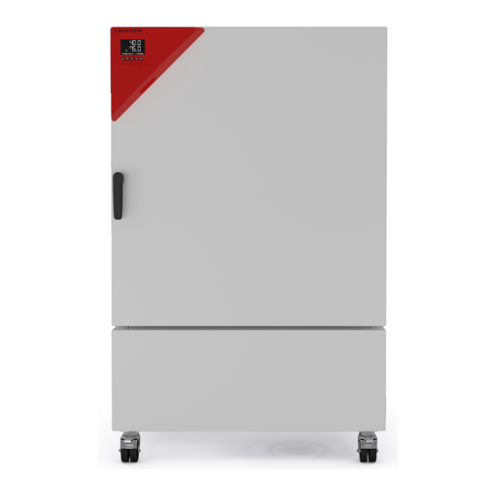
Page 18: Chamber Overview
Chamber overview Figure 4: Cooling incubator KB ECO / KB ECO-UL size 240 Main power switch Instrument panel with RD4 chamber controller and USB interface USB interfaces Door handle Chamber door Location of Peltier modules Power cable Ethernet interface KB ECO / KB ECO-UL (E6.2) 12/2021 Page 18/85... -
Page 19: Completeness Of Delivery, Transportation, Storage, And Installation
Note on second-hand chambers (Ex-Demo-Units): Second-hand chambers are chambers that were used for a short time for tests or exhibitions. They are thoroughly tested before resale. BINDER ensures that the chamber is technically sound and will work flaw- lessly. Second-hand chambers are marked with a sticker on the chamber door. Please remove the sticker before commissioning the chamber. -
Page 20: Storage
∅ Do NOT set the fork lifter from the chamber side. • Permissible ambient temperature range during transport: -10 °C / 14 °F to +60 °C / 140 °F. You can order transport packing for moving or shipping purposes from BINDER service. 3.3 Storage Intermediate storage of the chamber is possible in a closed and dry room. - Page 21 Do not install or operate the chamber in potentially explosive areas. DANGER Danger of explosion due to combustible dusts or explosive mixtures in the vicinity of the chamber. Serious injury or death from burns and / or explosion pressure. ∅ Do NOT operate the chamber in potentially explosive areas. ...
-
Page 22: Installation And Connections
Installation and connections Condensate collection pan Emerging condensate is collected in a condensate collection pan which is mounted under the chamber. If necessary, the pan can be removed and emptied at any time. Under normal operating conditions (e.g. incubation of 100 Petri dishes at 25 ° C) there is so little condensate that it will evaporate in the condensate collection pan so that the collection pan does not have to be emptied. -
Page 23: Electrical Connection
• Only use original connection cables from BINDER according to the above specification. UL chambers: Use only a UL Listed Power supply cord (UL category ELBZ), SJT 3x14 AWG (2.08 mm²);... -
Page 24: Functional Overview Of The Rd4 Chamber Controller
“Set points” menu directly at the controller or use the APT-COM™ 4 Multi Management Software (option) specially developed by BINDER. The controller offers various notifications and alarm messages with visual and audible indication. All con- troller settings remain valid until the next manual change. They are stored also after turning off the chamber. -
Page 25: Menu Structure Of The Controller And Access Levels
• Admin: The password enables access to advanced controller functions and settings. Factory setting is 00 01. • Service: The password enables access to all controller functions (for BINDER Service only). As soon as a password has been assigned, access to the respective functions is blocked and only available after entering the correct password. -
Page 26: Performance During And After Power Failures
To reduce odors quickly we recommend heating up the chamber to its nominal temperature for one day and in a well-ventilated location. WARNING: If customer should use a BINDER chamber running in non-supervised continu- ous operation, we strongly recommend in case of inclusion of irrecoverable specimen or samples to split such specimen or samples and store them in at least two chambers, if this is feasible. -
Page 27: Temperature Set-Point Entry
Temperature set-point entry Required access level: “User”. Setting range Control range -10 °C / 14 °F up to 70 °C / Temperature 20 ºC below ambient temperature up to 70 °C / 158 °F 158 °F. With safety controller mode “Limit”, adapt the safety controller always when you changed the temperature set-point. -
Page 28: Control By Date
Safety controller The safety controller settings remain in effect. Please note that with the set-point type offset, the automatic switchover can trigger a safety controller alarm. Recommended setting: Setpoint type “Limit” above the higher of the two set-points. The tolerance band alarm is always effective. Setting Path: Normal display... - Page 29 Setting the date: day The current setting flashes. Enter the desired day with the arrow but- tons. Confirm the entry with the OK button. Date <ON> Setting the date: month The current setting flashes. Enter the desired month with the arrow buttons.
-
Page 30: Regular Cyclic Control
Setting the date: day The current setting flashes. Enter the desired day, month, and year with the arrow buttons and confirm all entries each entry with the OK button. Date <OFF> With the arrow-down button you can change to enter the time to deactivate the alternative setpoint. Press the OK button to enable the setting Setting the time: hours The current setting flashes. -
Page 31: Entry Of The Alternative Temperature Set-Point
Setting the time: minutes The current setting flashes. Enter the desired minutes with the arrow buttons. Confirm the entry with the OK button. Time <ON> With the arrow-down button you can change to enter the day of the week to deactivate the alternative setpoint. -
Page 32: Activating / Deactivating "Idle Mode" Function
Activating / deactivating “Idle mode” function You can also activate the " Idle mode " function for the switching times set via the control by date and / or the cyclic control. This function is used to switch off all device functions except for the controller. With operating mode “Idle mode”, heating, refrigeration, and the fan are deactivated. -
Page 33: Special Controller Functions - Idle Mode
Special controller functions – Idle mode Required access level: “User”. Path: Normal display Setpoints Functions on/off You can define the switching state of up to four controller functions. Function 2 “Idle mode” serves to deactivate all chamber functions except the controller. With operating mode “Idle mode”, heating, refrigeration, and the fan are deactivated. -
Page 34: Password
Password 10.1 Password request To access menus for which access is restricted, you must enter the corresponding password. After calling the appropriate menu function with the OK button the password request appears. Password request. The left two digits are flashing. Enter the desired numbers with the ar- row buttons. -
Page 35: Assign And Modify A Password
10.2 Assign and modify a password In this menu you can assign and modify the passwords of the “User” and “Admin” access levels. Required access level: “Admin”. Keep the password well in mind. There is no access to the corresponding menu functions without the correct password. -
Page 36: Temperature Safety Devices
The user cannot restart the device again. The protective cut-off device is located internally. Only a service specialist can replace it. Therefore, please contact an authorized service provider or BINDER Service. 11.2 Overtemperature safety controller class 3.1 The chambers are regularly equipped with an electronic overtemperature safety controller (temperature safety device class 3.1 according to DIN 12880:2007). -
Page 37: Setting The Safety Controller Mode
11.2.1 Setting the safety controller mode Required access level: “User”. Path: Normal display Setpoints Safety controller Mode Press the OK button to enable the setting. Setting the safety controller mode The current setting flashes. Use the arrow buttons to select between LIMI (Limit) and OFFS (Offset). -
Page 38: Message And Measures In The State Of Alarm
11.2.3 Message and measures in the state of alarm The state of alarm is indicated visually in Normal display. If the buzzer is enabled (chap. 14.2) there is an additional audible alert. The heating turns off. As soon as the inner chamber temperature has cooled down below the safety controller value, the heating is released and temperature control continues. -
Page 39: General Controller Settings
General controller settings The general settings can be accessed in the “Settings” submenu, which is available for users with “Service” or “Admin” authorization level. It serves to enter date and time, select the language for the controller menus and the desired temperature unit and to configure the controller’s communication functions. The display of some network settings is available for all users in the “Chamber info”... -
Page 40: Setting The Current Date
12.3 Setting the current date Required access level: “Admin”. Following start-up of the chamber (chap. 6), it is “User”. Path: Normal display Settings Chamber Date Press the OK button to enable the setting. Setting the date: day The current setting flashes. Enter the current day with the arrow but- tons. -
Page 41: Function "Language Selection At Restart
12.6 Setting the chamber address This setting is required for the communication with the BINDER APT-COM™ 4 Multi Management Software. The chamber address settings in the chamber controller and in the software must be identical. Required access level: “Admin”. -
Page 42: Display Brightness
12.7 Display brightness Required access level: “Admin”. Path: Normal display Settings Chamber Brightness Press the OK button to enable the setting. Setting the display brightness The current setting flashes. Enter the desired value with the arrow but- tons. Setting range: 10% up to 100% Confirm the entry with the OK button. -
Page 43: Setting The Temperature Tolerance Range
13.2 Setting the temperature tolerance range Normal display Settings Various Temperature range Path: Press the OK button to enable the setting. Setting the temperature tolerance range The current setting flashes. Enter the desired temperature range with the arrow buttons. Entry range: 1.0 °C up to 10.0 °C Confirm the entry with the OK button. -
Page 44: Activating / Deactivating The Audible Alarm (Alarm Buzzer)
You can start and stop time or week programs at the RD4 controller. The programming itself has to be done using the APT-COM™ 4 Multi Management Software from BINDER (chap. 22.1). There you can create the programs and transfer them to the chamber controller. -
Page 45: Start Week Program
Ethernet network settings The settings of this submenu are used for networking chambers with an Ethernet interface, e.g. to connect them with BINDER’s APT-COM™ 4 Multi Management Software (option, chap. 22.1). 16.1 Showing the network settings Required access level: “User”. -
Page 46: Showing The Chamber's Mac Address
16.1.1 Showing the chamber’s MAC address Path: Normal display Chamber info Ethernet MAC address Display of the MAC address (exam- ple) Toggle forth and back with the Back button and the OK button. 00:00:00:00:00:00 MAC address With the arrow-down button you can now change to the next parameter (IP address). With the Back button you can go back to the “Ethernet”... -
Page 47: Showing The Standard Gateway
16.1.4 Showing the standard gateway Path: Normal display Chamber info Ethernet Standard gateway Display of the standard gateway (example) Toggle forth and back with the Back button and the OK button. Standard gateway 0.0.0.0 With the arrow-down button you can now change to the next parameter (DNS server address). With the Back button you can go back to the “Ethernet”... -
Page 48: Changing The Configuration Of The Network Settings
16.2 Changing the configuration of the network settings Required access level: “Admin”. The “Ethernet” submenu offers to subsequently or individually access the following settings: • Selecting the type of assignment (automatic or manual) of the IP address, chap. 16.2.1 If automatic IP address assignment has been selected: •... -
Page 49: Assigning The Ip Address
With the Back button you can go back to the “Ethernet” submenu and, repeatedly pressing it, to Normal display. 16.2.3 Assigning the IP address Access to this function is possible only if manual IP address assignment has been selected (chap. 16.2.1) Path: Normal display Settings... -
Page 50: Setting The Subnet Mask
16.2.4 Setting the subnet mask Access to this function is possible only if manual IP address assignment has been selected (chap. 16.2.1) Path: Normal display Settings Ethernet Subnet mask Press the OK button to enable the setting. The subnet mask entry is done in four steps, corresponding to the number sections: (1).(2).(3).(4) Principle of entry: •... -
Page 51: Data Recorder
(chap. 17.3). Temperature values are always given out in °C. • Chamber data for BINDER Service “DL2” This data is intended for use by BINDER Service. It also contains information from the self-test function. The storage rate is fix (1 minute). Temperature values are always given out in °C. -
Page 52: Storage Capacity
17.4 Deleting the data recorder When importing a configuration via USB stick and when loading a new firmware version by BINDER service, the entire data memory is deleted. BINDER service can also install the configuration by means of a setup program without deleting the data. -
Page 53: Usb Menu: Data Transfer Via Usb Interface
For detailed information on the file content see chap. 17.1. • Service data The "Service" folder is created on the USB stick and can be sent to BINDER Service. In addition to the configuration and recorder data, it contains further service-relevant information. -
Page 54: Export Functions
18.3 Export functions Required access level: any user Function “Export configuration”. To write the configuration data from the controller to the USB stick, press the OK button. Export configuration With the arrow-down button you can now change to the next function. Function “Export recorder data”. -
Page 55: Removing The Usb Stick
The results of the self-test are stored in the service recorder of the controller. You can export them using the controller’s USB interface and send them to BINDER Service (use function “Export recorder data” to USB stick, chap. 18). BINDER Service will evaluate the data using an analyzing tool. -
Page 56: Deactivating The Self-Test Mode
Display showing the running self-test in Normal display (example values) Self-test active Do not open and do not turn off the chamber while self-test is running. After an interruption of the voltage supply, the self-test restarts. If desired, you can cancel an ongoing self-test by deactivating the self-test function in the controller menu (chap. -
Page 57: Defrosting At Refrigerating Operation
Defrosting at refrigerating operation BINDER cooling incubators are very diffusion-proof. In favor of the high temperature accuracy, no automatic cyclical defrosting device is used. At very low temperatures the moisture in the air can condense on the heat sinks leading to icing. -
Page 58: Options
BINDER Data Logger Kit offers an independent long-term measuring system for temperature, available for different temperature ranges. The BINDER Data Logger is equipped with a keyboard and a large LCD display, alarm functions and a real-time function. Measurement data are recorded in the Data Logger and can be read out after the meas- urement via the RS232 interface of the Data Logger. -
Page 59: Cleaning
Do not use cleaning agents that may cause a hazard due to reaction with components of the device or the charging material. If there is doubt regarding the suitability of cleaning products, please contact BINDER service. We recommend using the neutral cleaning agent Art. No. 1002-0016 for a thorough cleaning. -
Page 60: Decontamination / Chemical Disinfection
For chemical disinfection, we recommend using the disinfectant spray Art. No. 1002-0022. Any corrosive damage that may arise following use of other disinfectants is excluded from lia- bility by BINDER GmbH. With every decontamination method, always use adequate personal safety controls. -
Page 61: Maintenance And Service, Troubleshooting, Repair, Testing
For personnel requirements please refer to the Service Manual. • Repair Repair of the chamber can be performed by BINDER Service or by BINDER qualified service partners or technicians, in accordance with the description in the Service Manual. After maintenance, the chamber must be tested prior to resuming operation. -
Page 62: Maintenance Intervals, Service
With an increased amount of dust in the ambient air, clean the Peltier fan grid (by suction or blowing) several times a year. We recommend taking out a maintenance agreement. Please consult BINDER Service: BINDER telephone hotline: +49 (0) 7462 2005 555... -
Page 63: Simple Troubleshooting
If there are is a technical fault or shortcoming, take the chamber out of operation and inform BINDER Service. If you are not sure whether there is a technical fault, proceed ac- cording to the following list. If you cannot clearly identify an error or there is a technical fault, please contact BINDER Service. -
Page 64: Sending The Chamber Back To Binder Gmbh
24.5 Sending the chamber back to BINDER GmbH If you return a BINDER product to us for repair or any other reason, we will only accept the product upon presentation of an authorization number (RMA number) that has previously been issued to you. An au- thorization number will be issued after receiving your complaint either in writing or by telephone prior to your sending the BINDER product back to us. -
Page 65: Disposal
(Elektro- und Elektronikgerätegesetz, ElektroG from 20 October 2015, BGBl. I p. 1739) or contact BINDER service who will organize taking back and disposal of the cham- ber according to the German national law for electrical and electronic equipment (Elektro- und El- ektronikgerätegesetz, ElektroG from 20 October 2015, BGBl. -
Page 66: Disposal Of The Chamber In The Member States Of The Eu Except For The Federal Republic Of Germany
Elektronikgerätegesetz, ElektroG from 20 October 2015, BGBl. I p. 1739). Instruct BINDER Service to dispose of the device. The general terms of payment and delivery of BINDER GmbH apply, which were valid at the time of purchasing the cham- ber. -
Page 67: Disposal Of The Chamber In Non-Member States Of The Eu
Danger of violation against existing law if not disposed of properly. Failure to comply with applicable law. Alteration of the environment. For final decommissioning and disposal of the chamber, please contact BINDER ser- vice. Follow the statutory regulations for appropriate, environmentally friendly disposal. -
Page 68: Technical Description
(certified since December 1996 by TÜV CERT). All test equipment used is subject to the administration of measurement and test equipment that is also a constituent part of the BINDER QM DIN EN ISO 9001 systems. They are controlled and calibrated to a DKD-Standard at regular intervals. -
Page 69: Kb Eco / Kb Eco-Ul Technical Data
26.4 KB ECO / KB ECO-UL technical data Chamber size 1020 Exterior dimensions Width, gross (incl. access port) mm / inch 932/ 36.69 1255 / 49.37 1254 / 49.37 Height, gross (incl. feet/castors) mm / inch 1461 / 57.52 1925 / 75.79 1925 / 75.79 Depth, net mm / inch 796 / 31.34 885 / 34.84 1149 / 45.24... -
Page 70: Equipment And Options (Extract)
26.5 Equipment and options (extract) To operate the chamber, use only original BINDER accessories or accessories / components from third-party suppliers authorized by BINDER. The user is responsible for any risk arising from using unauthorized accessories. Regular equipment... -
Page 71: Accessories And Spare Parts (Extract)
Qualification folder 26.6 Accessories and spare parts (extract) BINDER GmbH is responsible for the safety features of the chamber only, provided skilled electricians or qualified personnel authorized by BINDER perform all maintenance and repair, and if components relating to chamber safety are replaced in the event of failure with original spare parts. -
Page 72: Dimensions
26.7 Dimensions Dimensions size 240: [mm] KB ECO / KB ECO-UL (E6.2) 12/2021 Page 72/85... - Page 73 Dimensions size 720: [mm] KB ECO / KB ECO-UL (E6.2) 12/2021 Page 73/85...
- Page 74 Dimensions size 1020: [mm] KB ECO / KB ECO-UL (E6.2) 12/2021 Page 74/85...
-
Page 75: Certificates And Declarations Of Conformity
Certificates and declarations of conformity 27.1 EU Declaration of Conformity KB ECO / KB ECO-UL (E6.2) 12/2021 Page 75/85... - Page 76 KB ECO / KB ECO-UL (E6.2) 12/2021 Page 76/85...
- Page 77 KB ECO / KB ECO-UL (E6.2) 12/2021 Page 77/85...
-
Page 78: Certificate For The Gs Mark Of Conformity Of The "Deutsche Gesetzliche Unfallversicherung E.v." (German Social Accident Insurance) Dguv
27.2 Certificate for the GS mark of conformity of the “Deutsche Gesetzliche Unfallversicherung e.V.” (German Social Accident Insurance) DGUV KB ECO / KB ECO-UL (E6.2) 12/2021 Page 78/85... - Page 79 KB ECO / KB ECO-UL (E6.2) 12/2021 Page 79/85...
-
Page 80: Contamination Clearance Certificate
Contamination clearance certificate 28.1 For chambers located outside USA and Canada Declaration regarding safety and health Erklärung zur Sicherheit und gesundheitlichen Unbedenklichkeit The German Ordinance on Hazardous Substances (GefStofV), and the regulations regarding safety at the workplace, require that this form be filled out for all products that are returned to us, so that the safety and the health of our employees can be guaranteed Die Sicherheit und Gesundheit unserer Mitarbeiter, die Gefahrstoffverordnung GefStofV und die Vorschriften zur Si- cherheit am Arbeitsplatz machen es erforderlich, dass dieses Formblatt für alle Produkte, die an uns zurückgeschickt... - Page 81 Kind of transport / transporter / Transportweg/Spediteur: Transport by (means and name of transport company, etc.) Versendung durch (Name Spediteur o.ä.) ___________________________________________________________________________________ Date of dispatch to BINDER GmbH / Tag der Absendung an BINDER GmbH ___________________________________________________________________________________ KB ECO / KB ECO-UL (E6.2) 12/2021 Page 81/85...
- Page 82 We hereby commit ourselves and guarantee that we will indemnify BINDER GmbH for all damages that are a consequence of incomplete or incorrect information provided by us, and that we will exempt BINDER GmbH from eventual damage claims by third parties / Wir versichern, dass wir gegenüber BINDER für jeden...
-
Page 83: For Chambers Located In Usa And Canada
Please complete this form and the Customer Decontamination Declaration (next 2 pages) and attach the required pictures. E-mail to: IDL_SalesOrderProcessing_USA@binder-world.com After we have received and reviewed the complete information we will decide on the issue of a RMA num- ber. Please be aware that size specifications, voltage specifications as well as performance specifications are available on the internet at www.binder-world.us... - Page 84 Customer (End User) Decontamination Declaration Health and Hazard Safety declaration To protect the health of our employees and the safety at the workplace, we require that this form is com- pleted by the user for all products and parts that are returned to us. (Distributors or Service Organizations cannot sign this form) NO RMA number will be issued without a completed form.
- Page 85 4.5 Shipping laws and regulations have not been violated. I hereby commit and guarantee that we will indemnify BINDER Inc. for all damages that are a con- sequence of incomplete or incorrect information provided by us, and that we will indemnify and hold harmless BINDER Inc.
Need help?
Do you have a question about the KB ECO Series and is the answer not in the manual?
Questions and answers