Table of Contents
Advertisement
Operating Manual
APT.line™ KB (E3.1)
Refrigerated Incubators
with microprocessor program controller RD3
Model
KB 23 (E3.1)
KB 23-UL (E3.1)
KB 53 (E3.1)
KB 53-UL (E3.1)
KB 53 (115 V) (E3.1)
KB 115 (E3.1)
KB 115-UL (E3.1)
KB 115 (115 V) (E3.1)
BINDER GmbH
Address
Tel.
Fax
Internet
E-mail
Service Hotline
Service Fax
Service E-Mail
Service Hotline USA
Service Hotline Asia Pacific
Service Hotline Russia and CIS +7 495 98815 17
Issue 08/2012
Art. No.
9020-0112, 9120-0112
9020-0113, 9120-0113
9020-0114, 9120-0114
9020-0243, 9120-0243
9020-0115, 9120-0115
9020-0252, 9120-0252
9020-0116, 9120-0116
9020-0242, 9120-0242
9020-0117, 9120-0117
9020-0253, 9120-0253
Post office box 102
D-78502 Tuttlingen
+49 7462 2005 0
+49 7462 2005 100
http://www.binder-world.com
info@binder-world.com
+49 7462 2005 555
+49 7462 2005 93 555
service@binder-world.com
+1 866 885 9794 or +1 631 224 4340 x3
+852 39070500 or +852 39070503
Art. No. 7001-0115
Advertisement
Table of Contents

Related Manuals for Binder APT.line KB Series


Summary of Contents for Binder APT.line KB Series
- Page 1 9020-0252, 9120-0252 KB 115 (E3.1) 9020-0116, 9120-0116 9020-0242, 9120-0242 KB 115-UL (E3.1) 9020-0117, 9120-0117 KB 115 (115 V) (E3.1) 9020-0253, 9120-0253 BINDER GmbH Address Post office box 102 D-78502 Tuttlingen Tel. +49 7462 2005 0 +49 7462 2005 100 Internet http://www.binder-world.com...
-
Page 2: Ec - Declaration Of Conformity
EC – declaration of conformity EG - KONFORMITÄTSERKLÄRUNG EC - DECLARATION OF CONFORMITY CE - DECLARATION DE CONFORMITE Anbieter / Supplier / Fournisseur: BINDER GmbH Anschrift / Address / Adresse: Im Mittleren Ösch 5, D-78532 Tuttlingen Kühlbrutschränke mit Programmregelung Produkt / Product / Produit: Refrigerated incubators with program control Incubateurs réfrigérés à... - Page 3 Die oben beschriebenen Produkte sind konform mit folgenden harmonisierten Normen: The products described above are in conformity with the following harmonized standards: Les produits décrits ci-dessus sont conformes aux normes harmonisées suivantes: Sicherheit / safety / sécurité: EN 61010-1:2010 Sicherheitsbestimmungen für elektrische Mess-, Steuer-, Regel- und Laborgeräte –...
- Page 4 D-78532 Tuttlingen, 16.01.2012 BINDER GmbH P. M. Binder Dr. H. von Both Geschäftsführender Gesellschafter Leiter F & E Managing Director Director R & D Directeur général Chef de service R&D 3 / 3 KB (E3.1) 08/2012 page 4/84...
-
Page 5: Product Registration
Product registration KB (E3.1) 08/2012 page 5/84... -
Page 6: Table Of Contents
Contents EC – declaration of conformity ........................2 Product registration ............................5 SAFETY ........................8 Legal considerations ........................... 8 Structure of the safety instructions ...................... 8 1.2.1 Signal word panel ........................8 1.2.2 Safety alert symbol ........................9 1.2.3 Pictograms ..........................9 1.2.4 Word message panel structure .................... - Page 7 17.2.1 Cleaning ..........................67 17.2.2 Decontamination ........................68 17.3 Sending the unit back to BINDER GmbH ..................69 18. DISPOSAL......................70 18.1 Disposal of the transport packing ..................... 70 18.2 Decommissioning ..........................70 18.3 Disposal of the unit in the Federal Republic of Germany ..............70 18.4 Disposal of the unit in the member states of the EC except for the Federal Republic of Germany .
-
Page 8: Safety
Understanding and observing the instructions in this operating manual are prerequisites for hazard-free use and safety during operation and maintenance. In no event shall BINDER be held liable for any damages, direct or incidental arising out of or related to the use of this manual. -
Page 9: Safety Alert Symbol
CAUTION Indicates a potentially hazardous situation which, if not avoided, may result in moderate or minor (reversible) injury. CAUTION Indicates a potentially hazardous situation which, if not avoided, may result in damage to the product and/or its functions or of a property in its proximity. 1.2.2 Safety alert symbol Use of the safety alert symbol indicates a risk of injury. -
Page 10: Word Message Panel Structure
Risk of injury (UL units only) Unit front KB Unit front KB-UL Figure 1: Position of labels on the unit Keep safety labels complete and legible. Replace safety labels that are no longer legible. Contact BINDER service for these replacements. KB (E3.1) 08/2012 page 10/84... -
Page 11: Type Plate
Tel. + 49 (0) 7462/ 2005-0 Made in Germany Internet: www.binder-world.com Figure 3: Type plate (example of KB 115 regular unit 9020-0122) Indications of the type plate Information BINDER Manufacturer: BINDER GmbH KB 115 Model KB 115 Serial No. 00-00000 Serial No. 00-00000 100 °C... -
Page 12: General Safety Instructions On Installing And Operating The Refrigerated Incubator
(for Germany). BINDER GmbH is only responsible for the safety features of the unit provided skilled electricians or qualified personnel authorized by BINDER perform all maintenance and repair, and if components relating to chamber safety are replaced in the event of failure with original spare parts. -
Page 13: Intended Use
The refrigerated incubator KB does not dispose of any measures of explosion protection. DANGER Explosion hazard. Danger of death. ∅ Do NOT introduce any substance into the refrigerated incubator which is combustible or explosive at working temperature. ∅ NO explosive dust or air-solvent mixture in the inner chamber. Any solvent contained in the charging material must not be explosive or inflammable. -
Page 14: Unit Description
Any corrosive damage caused by such ingredients is excluded from liability by BINDER GmbH. WARNING: If customer should use a BINDER chamber running in non-supervised continuous operation, we strongly recommend in case of inclusion of irrecoverable specimen or samples to split such specimen or samples and store them in at least two chambers, if this is feasible. -
Page 15: Unit Overview
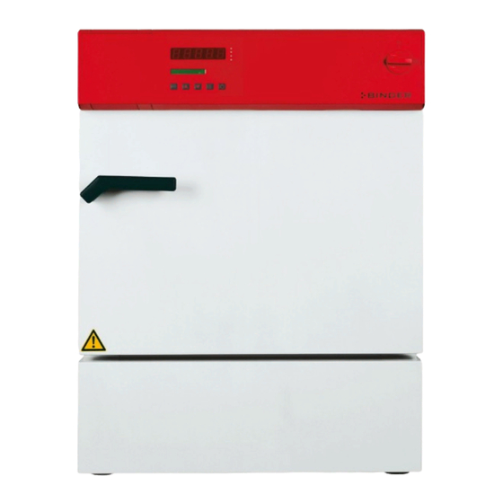
Unit overview Figure 4: Refrigerated incubator KB Main power switch On/Off Temperature controller RD3 Instrument panel Unit door Compressor housing Instrument panel Figure 5: Control panel of standard unit Main power switch On/Off Program controller RD3 Switch for interior illumination (option) KB (E3.1) 08/2012 page 15/84... -
Page 16: Completeness Of Delivery, Transportation, Storage, And Installation
Second-hand units are units that were used for a short time for tests or exhibitions. They are thoroughly tested before resale. BINDER ensures that the chamber is technically sound and will work flawlessly. Second-hand units are marked with a sticker on the unit door. Please remove the sticker before commissioning the unit. -
Page 17: Storage
Storage Intermediate storage of the unit is possible in a closed and dry room. Observe the guidelines for temporary decommissioning (chap. 18.2). • Permissible ambient temperature range during storage: -10 °C to +60 °C. • Permissible ambient humidity: max. 70 % r.H., non-condensing When after storage in a cold location you transfer the unit to its warmer installation site, condensation may form. -
Page 18: Installation Of The Equipment
Avoid any conductive dust in the ambiance according to the unit layout complying with pollution degree 2 (IEC 61010-1). Do not install or operate the unit in potentially explosive areas. DANGER Explosion hazard. Danger of death. ∅ Do NOT operate the unit in potentially explosive areas. ∅... -
Page 19: Start Up
To reduce odors quickly we recommend heating up the chamber to its nominal temperature for one day and in a well-ventilated location. WARNING: If customer should use a BINDER chamber running in non-supervised continuous operation, we strongly recommend in case of inclusion of irrecoverable specimen or samples to split such specimen or samples and store them in at least two chambers, if this is feasible. -
Page 20: General Indications
(setting in the user level, chap. 10). This setting is then valid for all program sections. Programming can be done directly via the controller keyboard or graphically at the computer using the communication software APT-COM™ 3 DataControlSystem (option, chap. 16.1) specially developed by BINDER. General indications The program controller RD3 offers several functional levels: Normal Display / fixed value operation: •... -
Page 21: Fixed Value Entry Mode
User level (chap. 10) • User specific controller settings • Setting the real time clock Normal Display / Fixed value operation 5 seconds Fixed value entry mode Program editor Program start level 5 seconds Menu visible only if week program Week program editor timer is activated in the user level 5 seconds... - Page 22 Press key Display 1 shows e.g. 37.0 (actual temperature set-point 2) (visible only if week program timer is activated in the user level, chap. 10) Display 2 shows SP2 TEMPERATURE (variable: temperature in °C) Enter temperature set-point in °C with arrow Value is shown in display 1.
-
Page 23: Week Program Editor
If the week program timer is active, depending on the running week program another set-point (SP2) may be targeted. Temperatures too high for the introduced solvent quantity can occur. Deactivate the week program timer if you do not use it (default setting, setting in the User level, chap. 10). CAUTION Too high or too low temperature. - Page 24 Display 1 shows 0000 Display 2 shows Shiftpt. (no function) Hit program key Display 1 shows 0000 Display 2 shows Shiftpt. (selection of the shift point) (actual shift point: 1) Value is shown in display 2. Select the shift point (1 up to 4) with key Hit program key Display 1 shows e.g.
-
Page 25: Program Table Template For Week Program Editor
Program table template for Week program Editor Program editor Program title Project Date: Day of the week Time Channel 1 Channel 2* (temperature) hh:mm ON = SP2 OFF = SP1 Monday Tuesday Wednesday Thursday Friday Saturday Sunday * Channel 2 is non-functional in the standard unit KB (E3.1) 08/2012 page 25/84... -
Page 26: Program Editor
Program editor Selecting between set-point ramp and set-point step You can program various kinds of temperature transitions. In the user level (chap. 10) you can select between the settings “Ramp” (default setting) and “Step”. Setting “Ramp” permits programming all kinds of temperature transitions. With setting “Step”... - Page 27 Program entry as set-point ramp (example): W/°C t/min. Program table corresponding to the diagram (with default setting “Ramp”): Section Temperature Section length Fan speed Operation lines set-point [ °C] [hh.mm] TEMP TIME O.LINE 00:30 01:30 01:00 03:20 00:01 * Only with option zero-voltage relay outputs via operation lines, see chap. 16.6. The values of such a program table can now be entered to the RD3 program controller (chap.
-
Page 28: Programming With Setting "Step
Program table corresponding to the diagram (with default setting “Ramp”): Section Temperature Section length Fan speed Operation lines set-point [ °C] [hh.mm] TEMP TIME O.LINE 00:30 00:01 01:30 00:01 01:00 00:01 03:20 00:01 * Only with option zero-voltage relay outputs via operation lines, see chap. 16.6. The values of such a program table can now be entered to the RD3 program controller (chap. -
Page 29: General Notes On Programming Temperature Transitions
Program table corresponding to the diagram (with setting “Step”): Section Temperature Section length Fan speed Operation lines set-point [ °C] [hh.mm] TEMP TIME O.LINE 00:30 01:30 01:00 03:20 * Only with option zero-voltage relay outputs via operation lines, see chap. 16.6. The values of such a program table can now be entered to the RD3 program controller (chap. - Page 30 The values of the program table can now be entered to the RD3 program controller. – Step 1 Selecting the program and the program section: Normal Display Display 1 shows e.g. 19.8 (actual temperature value) Display 2 shows e.g. 15.05.06 13:52 - - (actual date and time, actual state of week program timer channel 1: Off, channel 2: Off) for 5 sec...
- Page 31 Next step – set-point entry in the desired program sections: Basic entry principle: Access the parameters of individual program sections with button X/W one after the other. Enter the values of the individual parameters with the arrow keys. A value flashes once after 2 seconds thus indicating that it has been taken over to the controller.
- Page 32 Selecting the next program sections to be entered Display 1 shows e.g. 02 (section S02 selected) Display 2 shows P01: --- SEC. Section S02 has already been created. enter new set-points for the individual parameters with X/W. alternating CONTINUE X/W Display 1 shows e.g.
-
Page 33: Program Table Template For Program Editor
Program table template for Program Editor Program editor Program title Project Program No. Date: Section Temperature Section length Fan speed Operation lines * set-point [ °C] [hh.mm] TEMP TIME O.LINE * Only with option zero-voltage relay outputs via operation lines, see chap. 16.6. With the standard device the operation lines (O.LINE) are without any function. -
Page 34: Deleting A Program Section
Deleting a program section A program section is deleted from the program by setting the section duration to Zero. Normal display for 5 sec. Press down key Display 1 shows e.g. 0000 Display 2 shows PROGRAM EDITOR (you are in the program editor) Hit program key Display 1 shows 0000... -
Page 35: Program Start Level
The following section (in our example now S03) is displayed: Display 1 shows e.g. 03 (actually selected section: S03) Display 2 shows P01:S03 (program section can be selected) alternating CONTINUE X/W (information: set-point entry with X/W) or wait 120 sec Press key EXIT Controller returns to Normal Display If you delete a program section which is followed by further sections, those following move up... - Page 36 Deactivate the week program timer (factory setting, setting in the user level, chap. 10) before starting a program. Step 1 – Program selection (only with program type “2 programs” set): Normal Display Hit program key Display 1 shows e.g. 1 (actually selected program) Display 2 shows SEL.PRG.
-
Page 37: User Level
If you press button during program course, the entered set-points of the actually running program section are shown one after the other for 5 sec. each: Display 1 shows e.g. 25.5 (actual temperature value) Display 2 shows P01:S03 02:07:12 (actual program P01, actual section S03, and remaining time of program section S03) Press key Display 1 shows... - Page 38 • Safety controller set-point (Saf.setp) The temperature set-point setting of the safety controller (over temperature safety device class 3.1) is displayed and can be changed. An absolute value (e.g. 40 °C) in case of setting “limit” or a relative value (e.g. 2 °C) in case of setting “Offset” can be entered. Regularly check the setting of the set-point mode and of the over temperature safety device set-point entered in this mode for the temperature value in fixed value operation or for the maximum temperature value of the selected temperature program in program...
- Page 39 • Maximum section duration (Prg.Time) The maximum length of an individual program section can be set to either 99 hs 59 min or to 999 hs 59 min. This setting is then valid for all program sections. When changing the maximum duration setting, pre-existing programs will be deleted in the program editor.
- Page 40 • Date of the real time clock (Date) Main menu. Use the program key to access the settings of year, month, and day in the corresponding submenus. • Year of the real time clock (Year) Enter the year (2006 up to 2050) •...
- Page 41 Normal Display Display 1 shows e.g. 19.8 (actual temperature value) Display 2 shows e.g. 15.05.06 13:52 - - (actual date and time, actual switching state of week program timer channel 1: Off, channel 2: Off) for 5 sec Press down key Display 1 shows e.g.
- Page 42 Display 1 shows 0000 (no function) Display 2 shows Decimal: XXX.X (setting of decimal point position) (actual setting: XXX.X) Decimal point position XXX.X or XXXX. is Select decimal point position with arrow keys displayed in display 2. Press key Display 1 shows 0000 (no function) Display 2 shows...
- Page 43 Display 1 shows e.g. 3 (actual setting: 3 minutes) Display 2 shows Prt-Inv. (print interval) (actual setting: 3 min) Select value between 0 and 255 minutes Setting is displayed in displays 1 and 2. with arrow keys Press key Display 1 shows 0000 Display 2 shows Disp.LED: (continuous display illumination?)
- Page 44 Display 1 shows 0000 Display 2 shows 12h/24h (Display mode 12 hours or 24 hours? (actual setting: 24h) Select between 12 hours and 24 hours with Setting is displayed in display 2. arrow keys Press key Display 1 shows 0000 Display 2 shows Date (Main menu: Setting the date of the real time clock) Hit program key...
-
Page 45: Programming Example Of The Week Program Editor
Programming example of the Week Program Editor 11.1 Desired time function From Monday to Friday the chamber shall maintain a temperature of +20 °C, and during the week-end (Saturday and Sunday) a temperature of +5 °C. This program shall automatically run during the whole year, i.e. it shall be programmed just once. 11.2 Proceeding overview 1. - Page 46 Normal Display Display 1 shows e.g. 19.8 (actual temperature value) Display 2 shows e.g. 15.05.06 13:52 - - (actual date and time, actual switching state of week program timer channel 1: Off, channel 2: Off) for 5 sec Press down key Display 1 shows e.g.
- Page 47 Display 1 shows 0000 Display 2 shows 12h/24h (Display mode 12 hours or 24 hours? (actual setting: 24h) Press key Display 1 0000 shows Display 2 Date (Main menu: Setting the date of the real time clock) shows Hit program key Display 1 shows e.g.
- Page 48 2. Enter the set-points for the week program in Fixed value entry mode (see chap. 6) Set-points for the example program: • SP 1 (night / weekend) = 5 °C • SP 2 (day / week) = 20 °C Normal Display Display 1 shows e.g.
- Page 49 Normal Display Display 1 shows e.g. 19.8 (actual temperature value) (actual date and time, actual state of week program timer Display 2 shows e.g. 15.05.06 13:52 - - channel 1: Off, channel 2: Off) for 5 sec Press down key Display 1 shows e.g.
- Page 50 Display 1 shows e.g. --.-- (time of the selected shift point) (actually selected shift point: S1) Display 2 shows --:-- (actual setting: shift point not programmed) Hit program key Display 1 shows 06.00 (time of the selected shift point) (entry of time of the selected shift point) Display 2 shows Time 06:00 (actual setting: 6.00, i.e.
- Page 51 Display 1 shows 20.00 (time of the selected shift point) (entry of time of the selected shift point) Display 2 shows Time 20:00 (actual setting: 20.00, i.e. 8 p.m.) Value is shown in display 2. Enter the time 20:00 with arrow keys Press key Display 1 shows 0000...
-
Page 52: Example Programming For The Program Editor
Example programming for the Program Editor 12.1 Desired time function From Monday to Friday the chamber shall maintain a temperature of +20 °C, and during the week-end (Saturday and Sunday) a temperature of +5 °C. This program shall automatically run during the whole year, i.e. it shall be programmed just once. 12.2 Proceeding overview 1. -
Page 53: Proceeding In Detail
3. Set the number of cycles to infinite in the program start level and start the program The described example program must be started once at the precise moment of temperature change (on Monday e.g., at 0.01 or at 7.00). If the program cannot be manually started at the desired moment, you can program a suitable program delay-time of 99 hs. - Page 54 Display 1 shows 0000 Display 2 shows UserCod? 0000 (enter user code, display flashes) e.g. 0001 (basic setting, Enter the user code with arrow keys or the valid code in case it has been previously changed in this menu). Value is shown in both displays. Automatically forward after 2 sec Display 1 shows (actual address)
- Page 55 2. Enter the time program to the program editor Program table for the example program: Section Temperature Section length Fan speed Operation lines set-point [ °C] [hh.mm] TEMP TIME O.LINE 119:59 000:01 047:59 000:01 In this example the program is entered to the first program place (P01). Normal display Display 1 shows e.g.
- Page 56 Display 1 shows (actual section length set-point) Display 2 shows S01: TIME 119:59 (variable: section length in hhh:mm) alternating CONTINUE X/W (information: go on with X/W) Value is shown in both displays. Enter section length set-point of S01 of 119 hs.
- Page 57 Display 1 shows section S04 has been selected Display 2 shows P01: --- SEC. enter new set-points for the individual variables with button alternating CONTINUE X/W X/W. NEW SEC. X/W Select section S04 with arrow keys Press key Display 1 shows (actual temperature set-point) Display 2 shows S04:TEMP...
- Page 58 Display 1 shows actually selected number of program cycles: infinite Display 2 shows REPEAT (enter number of program cycles) Select number of cycles –1, i.e. infinite Value is shown in display 1. repeats, with arrow keys Hit program key Display 1 shows selected program Display 2 shows RUN PRG.
-
Page 59: Behavior In Case Of Failures
The user cannot restart the device again. The protective cut-off device is located internally. Only a service specialist can replace it. Therefore, please contact an authorized service provider or BINDER service. 14.2 Safety controller (temperature safety device class 3.1) The refrigerated incubator is regularly equipped with an electronic safety controller (over temperature safety device class 3.1 acc. - Page 60 Upper limit Set point value __________________ ------------------------------------- Lower limit __________________ ------------------------------------- Figure 8: Temperature safety device class 3.3 With a safety device class 3.1 a maximum value for the temperature is set that the unit will not exceed due to the regulatory function of the safety device class 3.1. This protection against excessively high temperatures can, for example, serve to protect the refrigerated incubator, its environment and the material under treatment from excess temperatures.
- Page 61 • Turn the control knob of the safety device using a coin to its end-stop (position 10) (unit protection). • When the set point is reached, turn back the control knob until its trip point (turn it counter-clockwise). • The trip point is identifiable by the red alarm lamp. •...
-
Page 62: Notes On Refrigerating Operation
Options 16.1 Communication software APT-COM™ 3 DataControlSystem (option) The unit is regularly equipped with a serial interface RS 422 that can connect the BINDER communication software APT-COM™ 3 DataControlSystem. The connection to a computer is established using the KB interface via an interface converter RS 422 / RS 232. -
Page 63: Protocol Printer (Option From Size 53 On)
The BINDER Data Logger is equipped with a keyboard and a large LCD display, alarm functions and a real-time function. Measurement data are recorded in the Data Logger and can be read out after the measurement via the RS232 interface of the Data Logger. -
Page 64: Additional Pt100 Temperature Sensor (Option From Size 53 On)
16.5 Additional Pt100 temperature sensor (option from size 53 on) An additional fixed or flexible temperature sensor Pt100 allows measuring the chamber temperature (fixed Pt100) or the temperature of the charging material (flexible Pt100) by means of an independent measuring system utilizing Pt100 entry. The sensor top protective tube of the flexible Pt100 can be immersed into liquid substances. -
Page 65: Water Protected Internal Socket (Option From Size 53 On)
A suitable DIN plug is enclosed. Operation line 1 Operation line 2 Operation line 3 Pin 1: Pin Pin 3: Pin Pin 5: Pin Pin 2: Make Pin 4: Make Pin 6: Make Switching state On: 1xx Switching state On: x1x Switching state On: xx1 Maximum loading capacity of the switching contacts: 24V AC/DC –... -
Page 66: Maintenance, Cleaning, And Service
With an increased amount of dust in the ambient air, clean the condenser fan (by suction or blowing) several times a year. We recommend taking out a maintenance agreement. Please consult BINDER Service. BINDER telephone hotline: +49 (0) 7462 2005 555... -
Page 67: Cleaning And Decontamination
Any corrosive damage that may arise following use of other cleaning agents is excluded from liability by BINDER GmbH. Any corrosive damage caused by a lack of cleaning, is excluded from liability by BINDER GmbH. CAUTION Danger of corrosion. -
Page 68: Decontamination
For chemical disinfection, we recommend using the disinfectant spray Art. No. 1002-0022. Any corrosive damage that may arise following use of other disinfectants is excluded from liability by BINDER GmbH. With every decontamination method, always use adequate personal safety controls. -
Page 69: Sending The Unit Back To Binder Gmbh
17.3 Sending the unit back to BINDER GmbH If you return a BINDER product to us for repair or any other reason, we will only accept the product upon presentation of an authorization number that has previously been issued to you. An authorization number will be issued after receiving your complaint either in writing or by telephone prior to your sending the BINDER product back to us. -
Page 70: Disposal
According to directive 2002/96/EC of the European Parliament and of the Council on waste electrical and electronic equipment (WEEE), BINDER devices are classified as “monitoring and control instruments” (category 9) only intended for professional use“. They must not be disposed of at public collecting points. - Page 71 (Elektro- und Elektronikgerätegesetz, ElektroG) from 23 March 2005, BGBl. I p. 762 or contact BINDER service who will organize taking back and disposal of the unit according to the German national law for electrical and electronic equipment (Elektro- und Elektronikgerätegesetz, ElektroG) from 23 March 2005, BGBl.
-
Page 72: Disposal Of The Unit In The Member States Of The Ec Except For The Federal Republic Of Germany
According to directive 2002/96/EC of the European Parliament and of the Council on waste electrical and electronic equipment (WEEE), BINDER devices are classified as “monitoring and control instruments” (category 9) only intended for professional use“. They must not be disposed of at public collecting points. -
Page 73: Disposal Of The Unit In Non-Member States Of The Ec
CAUTION Alteration of the environment. For final decommissioning and disposal of the unit, please contact BINDER service. Follow the statutory regulations for appropriate, environmentally friendly disposal. The main board of the refrigerated incubator includes a lithium cell. Please dispose of it according to national regulations. - Page 74 115V or 230V. Check unit fuse and replace it if Unit fuse has responded. appropriate. If it responds again, Unit without function. contact BINDER service. Controller defective. Nominal temperature exceeded Contact BINDER service. by 10° due to unit failure. Over temperature protective device (class 1) responds.
-
Page 75: Technical Description
(certified since December 1996 by TÜV CERT). All test equipment used is subject to the administration of measurement and test equipment that is also constituent part of the BINDER QM DIN EN ISO 9001 systems. They are controlled and calibrated to a DKD-Standard at regular intervals. -
Page 76: Kb Technical Data
20.4 KB technical data Unit size Exterior dimensions Width mm / inch 433 / 17.05 634 / 24.96 834 / 32.83 Height (incl. feet) mm / inch 618 / 24.33 837 / 32.95 1022 / 40.24 Depth mm / inch 516 / 20.31 576 / 22.68 646 / 25.43... -
Page 77: Equipment And Options
20.5 Equipment and Options To operate the refrigerated incubator, use only original BINDER accessories or accessories / components from third-party suppliers authorized by BINDER. The user is responsible for any risk arising from using unauthorized accessories. -
Page 78: Spare Parts And Accessories
-- Not available 20.6 Spare parts and accessories BINDER GmbH is only responsible for the safety features of the unit provided skilled electricians or qualified personnel authorized by BINDER perform all maintenance and repair, and if components relating to chamber safety are replaced in the event of failure with original spare parts. -
Page 79: Contamination Clearance Certificate
Contamination clearance certificate 21.1 For units located outside North America and Central America Declaration regarding safety and health Erklärung zur Sicherheit und gesundheitlichen Unbedenklichkeit The German Ordinance on Hazardous Substances (GefStofV), and the regulations regarding safety at the workplace, require that this form be filled out for all products that are returned to us, so that the safety and the health of our employees can be guaranteed. - Page 80 Kind of transport / transporter / Transportweg/Spediteur: Transport by (means and name of transport company, etc.) Versendung durch (Name Spediteur o.ä.) ___________________________________________________________________________________ Date of dispatch to BINDER GmbH / Tag der Absendung an BINDER GmbH: ___________________________________________________________________________________ KB (E3.1) 08/2012 page 80/84...
- Page 81 We are aware that, in accordance with Article 823 of the German Civil Code (BGB), we are directly liable with regard to third parties, in this instance especially the employees of BINDER GmbH, who have been entrusted with the handling / repair of the unit / component. / Es ist uns bekannt, dass wir gegenüber Dritten –...
-
Page 82: For Units In North America And Central America
Please complete this form and the Customer Decontamination Declaration (next 2 pages) and attach the required pictures. E-mail to: IDL_SalesOrderProcessing_USA@binder-world.com After we have received and reviewed the complete information we will decide on the issue of a RMA number. Please be aware that size specifications, voltage specifications as well as performance specifications are available on the internet at www.binder-world.us... - Page 83 Customer (End User) Decontamination Declaration Health and Hazard Safety declaration To protect the health of our employees and the safety at the workplace, we require that this form is completed by the user for all products and parts that are returned to us. (Distributors or Service Organizations cannot sign this form) NO RMA number will be issued without a completed form.
- Page 84 Shipping laws and regulations have not been violated. I hereby commit and guarantee that we will indemnify BINDER Inc for all damages that are a consequence of incomplete or incorrect information provided by us, and that we will indemnify and hold harmless BINDER Inc.
Need help?
Do you have a question about the APT.line KB Series and is the answer not in the manual?
Questions and answers