
Related Manuals for Elmo TD4114 IP II


Summary of Contents for Elmo TD4114 IP II
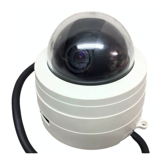
- Page 1 Domed Camera TD4114 IP INSTRUCTION MANUAL Please read this instruction manual carefully before using TD4114 IP and keep it for future reference.
-
Page 2: Important Safety Instructions
IMPORTANT SAFETY INSTRUCTIONS 1. Read these instructions. 2. Keep these instructions. 3. Heed all warnings. 4. Follow all instructions. 5. Do not use this apparatus outdoors. 6. Do not use this apparatus near water. 7. Clean only with dry cloth. 8. - Page 3 INFORMATION CAUTION RISK OF ELECTRIC This equipment has been tested SHOCK DO NOT OPEN and found to comply with the CAUTION : TO REDUCE THE RISK OF limits for Class A digital device, ELECTRIC SHOCK. DO NOT REMOVE COVER (OR BACK). pursuant to Part 15 of the FCC NO USER SERVICEABLE PARTS INSIDE.
-
Page 4: Handling Precautions
HANDLING PRECAUTIONS I Do not use any AC adapter other than the one supplied with the product. I This Camera has no power switch. Before maintenance, disconnect the power plug from the outlet. I This Camera is designed only for use indoors. Do not use this Camera out of doors. - Page 5 • We will not be liable for any damage arising out of or resulting from malfunction or hung-up of the product due to the use of an appliance or software we are not involved in for the product. • We will not be liable for any damage arising out of or resulting from repairs or tampering of the product by yourself or any unauthorized third party.
-
Page 6: Table Of Contents
CONTENTS IMPORTANT SAFETY INSTRUCTIONS ............1 HANDLING PRECAUTIONS ................3 CONTENTS......................5 1. PART NAMES AND FUNCTIONS ..............7 [1] Main unit.......................7 [2] Back panel ......................8 2. SETTING UP ....................9 [1] Installation ......................9 [2] How to adjust the video..................12 [3] Drawing the Composite Cable from the Camera Back Face ......13 [4] Connection of the Camera .................14 3. - Page 7 [4] MPEG4 Viewer software [ELMO 1Channel Viewer] .........47 (1) Restrictions ....................47 (2) Connection ....................47 (3) Live display ....................49 (4) Sound ......................50 (5) Settings ......................51 (6) MPEG4 Setup ....................52 (7) JPEG Setup ....................53 (8) Network Setup .....................54 (9) Alarm Setup ....................56 (10) E-mail Setup ....................57...
-
Page 8: Part Names And Functions
1. PART NAMES AND FUNCTIONS Main unit BOTTOM OF MAIN UNIT Name Function MAIN UNIT Main unit of the camera. ZOOM RING Adjusts the image size. FOCUS RING Adjusts the focus. LENS COVER Protects the lens. MAIN UNIT COVER Protects the main unit. ETHERNET TERMINAL RJ-45 connector for Ethernet. -
Page 9: Back Panel
Back panel Name Function TILT SET SCREW Fixes the up/down direction of video after its adjustment. MAIN UNIT SET SCREW HOLE Fixes the main unit. ALARM IN-OUT TERMINAL To be connected to an alarm device. (6P connector (black)) VIDEO OUT TERMINAL To be connected to the image input terminal of a (BNC jack) monitor TV or VTR. -
Page 10: Setting Up
2. SETTING UP [1] Installation (1) Mounting the Fixing Plate 1.Make mounting holes and a cord hole in the place (ceiling) to which this Camera is installed. FRONT MOUNTING HOLE (prepared hole) for FIXING PLATE, 4 locations 85.7mm(3-3/8inch) ø72 (cord hole) WARNING:The total mass of the main unit and fixing plate is approx. - Page 11 3. Match the [ ] mark on the fixing plate with the [ ] mark on the back face of the main unit, set the tabs (3 locations) of the back face of the main unit in the mating cuts (3 locations) of the fixing plate, and turn the main unit clockwise by 25°...
- Page 12 (2) Mounting the Safety Wires 1.Loop up one end of the Safety Wires through the respective safety wire looping holes made on the Ceiling Plate, and then loop up the other end of the same around the beams or anything that is used to mount ceiling tile channel for structure safety. SAFETY WIRE (not supplied) SAFETY WIRE LOOPING HOLE...
-
Page 13: How To Adjust The Video
[2] How to adjust the video 1. Turn the main unit cover counterclockwise MAIN UNIT COVER (in the direction indicated by arrows). 2. Watching the monitor, adjust the shooting PAN BASE direction. • Clockwise/counterclockwise direction Turn the pan base clockwise/ counterclockwise to adjust the right/left direction. -
Page 14: Drawing The Composite Cable From The Camera Back Face
4. Attach the lens cover. MAIN UNIT LENS COVER MAIN UNIT COVER 5. Attach the main unit cover and turn it MAIN UNIT clockwise (in the direction indicated by arrows). MAIN UNIT COVER [3] Drawing the Composite Cable from the Camera Back Face 1.Remove the blank cover from the back face of the Camera base , and draw the composite cable from the back face of the Camera. -
Page 15: Connection Of The Camera
[4] Connection of the Camera Speaker AUDIO OUTPUT (Green) with amplifier Microphone AUDIO INPUT (Blue) RELAY CABLE (supplied) VIDEO OUT VIDEO CABLE To SENSOR and (commercial item, EXTERNAL CONTROL BNC, co-axial) ALARM IN-OUT TERMINAL DC IN (6P connector (black)) COMPOSITE CABLE To MONITOR (part of the Camera) VIDEO IN... -
Page 16: Alarm
3. Alarm Alarms are caused by “alarm 1”, “alarm 2”, and “motion detection”. You can set an alarm action for each cause. “With/Without alarm”, “Send e-mail/Send FTP/Both/None” are available. Note: An alarm remains output from the alarm output terminal for ten seconds. -
Page 17: Sound
Camera. For further information about operation, see “Speaker” on page 27 and “(4) Sound” on page 50. Note: When the dedicated software, “ELMO 1Channel Viewer”, is used for the connection between a client and the Camera, no sound will be transmitted or received if you select [MPEG4 Setting] –... -
Page 18: Initializing The Settings
5. INITIALIZING THE SETTINGS G Set the DIP switch No. 2 to ON to turn on the power. In ten seconds, all of the camera and network settings will be reset to the factory settings. After the power is turned OFF, set the DIP switch No. 2 to OFF. Note: Set the DIP switch to OFF after initialization. -
Page 19: Operation Procedures
Camera on a Web browser. • MPEG4 server function ..For displaying live images and snapshots and remote- operating the Camera on dedicated client software (ELMO 1 Channel Viewer: hereinafter called “Viewer”). • Sound server function ... For receiving sound on a Web browser. For receiving or transmitting sound on a Viewer. - Page 20 G Preparations before connection Before connection, determine an IP address and a subnet mask to be set in the Camera. For the IP address and the subnet mask, contact the administrator of the network you intend to use. The network settings of the Camera made by the factory are as follows: IP address: 192.168.1.10 Subnet mask: 255.255.255.0...
- Page 21 • Connection to a host (For operation at DC12V) Connect the Ethernet terminal (RJ-45) of the Camera and that of the host with each other using the attached Ethernet cross cable or an Ethernet cross cable (UTP category 5 or more) commercially available.
-
Page 22: Install
Viewer Install wizard. G Installing Viewer Install Viewer by running the “ELMO 1Channel Viewer install program” on the attached CD-ROM and opening Install Wizard. As soon as the wizard begins to run, the following screen appears. -
Page 23: Web Browser
G Uninstalling Viewer Open “Add/Delete Software” (“Add/Delete Applications” for Windows2000) on “Control Panel” then select “ELMO 1Channel Viewer” from the installed programs, and press the [Change] button. When the following screen is displayed, select “Remove” and press the [Next] button to uninstall the ELMO 1Channel Viewer. -
Page 24: Connection
(2) Connection Start the Web browser on the host networked to the Camera. Note: In the example of connection, Microsoft Internet Explorer is used. 1. Enter the IP address of the Camera in the URL input field on the Web browser. 1. - Page 25 3. The page shown below is displayed on the Web browser. 4. Select English or Japanese. Note: To display information in Japanese, the browser must be capable of properly displaying Japanese pages. 5. The main page is displayed. • Home ........Displays the main page. •...
- Page 26 • Live View (QQVGA) ... Displays live images with a size of 160 × 120. • Capture View (Half-D1) ..Displays capture images with a size of 704 × 480. • Capture View (SIF) ....Displays capture images with a size of 352 × 240. •...
-
Page 27: Live Display
(3) Live display Live images taken by the Camera are displayed. On the main page, select the size of images you want to display live from [Live View (Half- D1)], [Live View (SIF)], and [Live View (QQVGA)]. The sizes of live images are shown below. •... - Page 28 w Iris ........Adjusts the iris. The auto iris (the automatic adjustment function to keep brightness at the same level even if the state of the object changes) is valid at all times. Use the “Open” and “Close” buttons to “increase” or “decrease” brightness.
-
Page 29: Capture Display
Note: Half-D1 size images are saved in 704 x 240, meaning that they are landscape. They can be viewed in the size of 704 x 480 on “Image Viewer” that is installed together with “ELMO 1Channel Viewer”. Note: The procedure described above may depend on the browser. -
Page 30: Settings
(5) Settings You can make all settings relating to the Camera. You can jump to pages on which settings for the Camera can be made. To go to each setup page, click on the corresponding link on the screen shown below. Note: To change the settings, login by the administrator authority should have been completed. -
Page 31: External Gpio Setup
(6) External GPIO Setup You can set the activation mode of the external GPIO. • Activation Mode ....Used to set the output mode of the external GPIO output terminal. The GPIO is controlled by the ON/OFF of the activation mode and GPIO. -
Page 32: Jpeg Setup
(setting range: 30, 15, 10, 5, and 1 frames/second). Note: When the frame rate is set to “1” or “5”, sound can not be transmitted or received by using “ELMO 1Channel Viewer”. • Resolution ......Designate the size of images to be displayed. -
Page 33: Network Setup
(9) Network Setup Make settings relating to the network. Note: Prior to making network settings, be sure to consult the network administrator of the network to be used. Note: If the setting of this item is changed, the connection setting of the Camera may need to be changed. - Page 34 Multicast ......UDP image data is distributed, irrespective of whether the Camera is connected or is not connected from the host, resulting in a decrease in the load on the Camera and the transmission line. Although any number of addresses can be set, image data may not be distributed properly depending on the network environment.
-
Page 35: Alarm Setup
(10) Alarm Setup Make settings relating to alarms. • Alarm 1 / 2 / Motion Detection Title ......Set any desired title of alarm 1/ 2 or motion detection (with up to 32 characters). Note: Two-byte characters, including Japanese characters, are not available for a title. -
Page 36: E-Mail Setup
by FTP and e-mail will be transmitted at the same time. • Alarm 1 / 2 / Motion Detection Matched Resolution .......Designate the size of JPEG images to be attached when transferring the FTP or transmitting e-mail as set at Alarm 1/2 Action. - Page 37 • SMTP Address...... Designate the SMTP server to be used (with up to 32 characters). • POP Address......Designate the POP server to be used (with up to 32 characters). • Use Authentication ....Designate whether to use user authentication on the SMTP server to be used.
-
Page 38: Ftp Setup
(12) FTP Setup Make settings relating to FTP connection. • IP........... Designate the IP address of the server to which the FTP will be transmitted. • Port........Designate the port number of the FTP server to which the FTP will be transmitted. It is not generally necessary to change the setting (21, 1024 to 65535). - Page 39 •Time Store ......Set whether to regularly transmit and save images in the FTP server. • Time Store login each send .. Set whether to connect to the FTP server each time images are transmitted or not (always connected). • Time Store dwell time ..Set the interval at which images will be saved when Time Store is valid (30 to 180 seconds).
-
Page 40: User Setup
(13) User Setup Make settings relating to user administration. • Adding a new user You can register a login ID, a password, and authority for connection to the Camera. Designate an authority, enter a login ID and a password, and then click on the [Add] button. - Page 41 • Modifying a user You can modify the registered login ID, password, and authority of any user for connection to the Camera. Select the user you want to modify from the list. Designate the authority, enter the login ID and password, and press the [Modify] button. Note: With regard to “root”, only the password can be changed.
-
Page 42: Ip Filtering Setup
(14) IP filtering Setup Make settings relating to the IP filter. Note: Making the settings described here may prevent connection to the Camera. Perform the setting operation with extreme care. Note: “Start IP” cannot be set larger than “End IP”. •... -
Page 43: Camera Control Setup
• Modifying an address Select the address you want to modify from the list. Change the “start address” and the “end address”, and click on the [Modify] button. The data will be corrected. • Deleting an address Select the address you want to delete from the list, and click on the [Remove] button. (15) Camera Control Setup Make settings relating to the Camera. -
Page 44: Camera Settings
• Control Duration Time ..Designate the period during which a client maintains control when “Time Slice Share” is selected at “Control Policy” (setting range: 1 to 60 minutes). (16) Camera Settings P.43 P.45 (17) Camera Settings (AE Settings) - 43 -... - Page 45 Name Function E-ZOOM To set the maximum magnification [OFF, 1.1×, 1.2×, 1.4×, 1.6×, 1.8×, 2.0×, 2.2×, 2.4×, 2.6×, 2.8×, 3.0×, 3.5×, 4.0×] To select the high-speed shutter speed [OFF (1/60s), 1/100s, 1/250s, HS-SHUTTER 1/500s, 1/1000s, 1/2000s, 1/4000s, 1/10000s, 1/20000s, 1/50000s]. When [LS-SHUTTER] is [ON], the shutter speed can be selected from [OFF (1/60s) 1/100s].
-
Page 46: Camera Settings (Picture Settings)
(18) Camera Settings (Picture Settings) Name Function To set the backlight compensation function to [ON/OFF]. When there is an intensive light in the background, this function prevents the object from becoming dark. BLC MODE To select the Backlight Compensation Setting mode [AREA/HIST]. About the Backlight Compensation Setting mode To select the image area of the object that needs an appropriate AREA... -
Page 47: System Time Setup
Name Function To select the White Balance Setting mode [ATW, AWC, INDOOR, OUTDOOR, FL-LIGHT, MWB]. About the White Balance Setting mode To adjust the white balance by way of continuous, automatic following. (When the image is in a single color all over, the white balance may not be ajusted correctly.) To adjust the white balance according to the then shooting status. -
Page 48: Mpeg4 Viewer Software [Elmo 1Channel Viewer]
[4] MPEG4 Viewer software [ELMO 1Channel Viewer] (1) Restrictions Access to the Camera through “ELMO 1Channel Viewer” (hereinafter referred to as “Viewer”) needs your computer to meet the following operating requirements: • Microsoft Windows 2000 or XP. • DirectX 9.0C or a later version is installed. - Page 49 2. Viewer’s main screen is displayed. 3. Select [Camera] – [Connect], and the Connect Dialog screen appears. 4. Enter the IP address, login name (ID), password, and connection port of the Camera you want to connect, and click on the [OK] button. Viewer will be connected to the Camera, and the screen will display an MPEG4 image and the Control Panel.
-
Page 50: Live Display
(3) Live display When double-clicking on the image, the image is enlarged to full screen. When double- clicking again on the image, the image display returns to the original size. • Obtaining snapshots You can save snapshots, which are in sizes of Half-D1, SIF, and QQVGA, on the Camera in a specific folder. -
Page 51: Sound
• Control Panel • Iris Open / Close....... Adjusts the iris. Normal ....... Adjusts the brightness to the normal level. *The auto iris (the automatic adjustment function to keep brightness at the same level even if the state of the object changes) is valid at all times. •... -
Page 52: Settings
(5) Settings You can change the settings for the Camera. Select [Setup] from the menu bar, and the setting menu shown below appears. Note: To change the settings, login by the administrator authority should have been completed. Note: Those characters available for setting each item are only the one-bite alphanumeric characters and special characters (@, –, _, ¥, /, ', ", .). -
Page 53: Mpeg4 Setup
(6) MPEG4 Setup Make settings for obtaining MPEG4 images. Note: By changing this setting, the Camera itself may be reset and become incapable of distributing images for a while. • Quality ........Designate the upper limit to the data amount to limit the data amount generated during communication or image distribution (GOP: 64 to 2000 kbps, Frame: 500 to 2000 kbps). -
Page 54: Jpeg Setup
(7) JPEG Setup Set image quality for JPEG images. • JPEG Quality ......Designate image quality. High........High image quality. Although high-quality images can be obtained, the load on the transmission line increases. Normal ....... Medium image quality with a compression rate between High and Low. -
Page 55: Network Setup
(8) Network Setup Make settings relating to the network. Note: Before making network settings, consult the administrator of the network you are going to use. Note: If this item is changed, the connection setting for the Camera may need to be changed. In this case, make the proper connection setting, and reconnect the Camera. - Page 56 • Gateway ........ Designate the IP address of a router when it is used to connect the Camera to an external network. • DNS1/DNS2 ......Set the address of a DNS server to which the Camera is to be connected. At DNS2, set the address of the DNS server to which the Camera will be connected if it cannot connect to DNS1.
-
Page 57: Alarm Setup
(9) Alarm Setup Make settings relating to alarms. • Alarm 1 / 2 / Motion Detection Title ......Set any desired title of alarm 1/ 2 or motion detection (with up to 32 characters). Note: Two-byte characters, including Japanese characters, are not available for a title. -
Page 58: E-Mail Setup
• Alarm 1/2 Output....Set whether to output an alarm when an alarm signal is input to alarm input 1 or 2. • Motion Detection Alarm Out..Set whether to give alarm output when a motion is detected. (10) E-mail Setup Make settings relating to e-mail. -
Page 59: Ftp Setup
• Message ........ Set a text to be sent as a message when transmitting e-mail (with up to 64 characters). Note: Two-byte characters, including Japanese characters, are not available for a Message. Use one-byte alphanumerical characters. • Use Authentication ....Designate whether to use user authentication on the SMTP server to be used. - Page 60 • Passive Mode ......Designate whether to use passive mode or active mode for transferring the FTP. Use passive mode when there are restrictions on the ports because of a firewall, etc. • Time Store Dwell Time ..Set the interval at which images will be saved when Time Store is valid (30 to 180 seconds).
-
Page 61: Motion Detection Setup
(12) Motion Detection Setup • Use Motion Detection... Set whether to perform motion detection. • Sensitivity ......Set the sensitivity of motion detection. • Area settings When “Select” under “Tools” is checked, the area on the screen that is selected by drag &... -
Page 62: User Setup
(13) User Setup Make settings relating to user administration. • Adding a new user You can register a login ID, a password, and authority for connection to the Camera. Designate an authority, enter a login ID and a password, and then click on the [Add] button. - Page 63 • Modifying a user You can modify the registered login ID, password, and authority of any user for connection to the Camera. Select the user you want to modify from the list. Designate the authority, enter the login ID and password, and press the [Modify] button. Note: For to “root,”...
-
Page 64: Ip Filtering Setup
(14) IP filtering Setup Make settings relating to the IP filter. Note: Making the settings described here may prevent connection to the Camera. Perform the setting operation with extreme care. Note: “Start IP” cannot be set larger than “End IP”. •... -
Page 65: Snapshot Setup
(15) Snapshot Setup Make settings relating to snapshots on this screen. • Path ........Set a directory for saving snapshots. In snapshot saving, the [MAC address] folder and [Date] folder of the Camera connected to the set path folder are created, and snapshots are saved there. -
Page 66: Color Setup
(16) Color Setup Set the brightness, contrast, hue, and saturation of images on this screen. • Brightness ......Sliding the control knob to the right makes the image brighter. • Contrast......... Sliding the control knob to the right makes the contrast stronger. -
Page 67: Camera Control Setup
(17) Camera Control Setup Make settings relating to the Camera. • Control Policy....... Designate the mode of controlling the Camera. All-Time Share....The control policy remains unless the client having an operation authority cuts off the connection. Time Slice Share ....The operation authority will be released as soon as the time set at “Control Duration Time”... -
Page 68: External Gpio Setup
(18) External GPIO Setup You can set the activation mode of the external GPIO. • Activation Mode ....Used to set the output mode of the external GPIO output terminal. The GPIO is controlled by the ON/OFF of the activation mode and GPIO. -
Page 69: Camera Settings (Picture Settings)
(20) Camera Settings (Picture Settings) For each setting item, see the description of each function on page 45. (21) System Time Setup Set the internal clock of the Camera. The time of this clock will be added to the file name when sending an E-mail or FTP. -
Page 70: Tools
(22) Tools Select [Tools] from the menu bar, and the Tool menu shown below appears. • Display Motion Detection ..Displays an area in which some motion is detected on the MPEG4 live image screen. • External GPIO On ....Turns ON or OFF output from the general-purpose output terminal. -
Page 71: Firmware Update
• Open Snapshot Folder ..Opens the file designated at Path on the Snapshot Setup screen. • Image Viewer ....... Displays the JPEG images saved in the PC. Displays the JPEG images in D1, which was acquired in Half-D1. • Language Setup ....Set English or Japanese for Viewer (the selection becomes valid after Viewer is turned OFF and ON again). - Page 72 3. Turn ON the power to the Camera, and select [Tool] – [Network Update] from the menu bar of Viewer on the host. 4. The Net Update window opens. Set correct data at each of IP (the Camera’s IP address), Port (the Camera’s optional port number), ID (the Camera’s administrator login name), and Password (the Camera’s login password).
-
Page 73: Set Items
[5] Set items G AE Settings Name Function Factory settings E-ZOOM To set the maximum magnification [OFF, 1.1x, 1.2x, 1.4x, 1.6x, 1.8x, 2.0x, 2.2x, 2.4x, 2.6x, 2.8x, 3.0x, 3.5x, 4.0x] HS-SHUTTER To select the high-speed shutter speed [OFF (1/60s), 1/100s, 1/250s, 1/500s, 1/1000s, 1/2000s, 1/4000s, 1/10000s, 1/20000s, 1/50000s]. - Page 74 G PICTURE Settings Name Function Factory settings To set the backlight compensation function to [ON/OFF]. OFF When there is an intensive light in the background, this function prevents the object from becoming dark. BLC MODE To select the Backlight Compensation Setting mode AREA [AREA/HIST].
- Page 75 Name Function Factory settings INDOOR This function is selected to shoot indoors. The color temperature is assumed to be 3200K. OUTDOOR This function is selected to shoot outdoors. The color temperature is assumed to be 6300K. This function is selected when the Camera is used LIGHT under the fluorescent illumination.
- Page 76 Open and the GND level becomes valid during output. Normal Close: The GND level is usually activated, and high impedance becomes valid during output. G MPEG4 Make settings for MPEG4 display using “ELMO 1Channel Viewer”. Name Function Factory settings Quality...
- Page 77 G Network Consult the administrator of the network you intend to use before making network settings. Name Function Factory settings MPEG4 Select a MPEG4 distribution method. Send Type UDP Unicast: A method of sending the UDP image Unicast data by the connection request from the client. Multicast: A method of sending the same UDP image data to the multiple addresses in the same network.
- Page 78 G Alarm Name Function Factory settings Alarm 1 Title Set any desired title of alarm 1. Event1 * Two-byte characters, including Japanese characters, are not available for a title. Use one-byte alphanumerical characters. Alarm 1 Select the mode of the alarm to be effective when None Action an alarm input signal (no-voltage make contact) is...
- Page 79 Name Function Factory settings Matched Designate the size of JPEG images to be attached Resolution when transmitting the FTP or transmitting e-mail as (Alarm 2) set at Alarm 2 Action. Half-D1/SIF/QQVGA Motion Set any desired title of Motion Detection. Motion Detection Two-byte characters, including Japanese characters, Detection...
- Page 80 G E-mail Name Function Factory settings E-mail Designate the address to which e-mail will be None transmitted. E-mail from Designate the e-mail address of the Camera. None E-mail CC1 Designate an address to which e-mail will be None / CC2 transmitted at the same time when it is sent to the / CC3 e-mail address set at To.
- Page 81 G FTP Name Function Factory settings IP address Designate the IP address of the server to which the 0.0.0.0 FTP will be transferred. Port number Designate the port number of the FTP server to which the FTP will be transferred. User ID Designate an account name for connection to the None...
- Page 82 G User Name Function Factory settings User list Registered login IDs and authorities are displayed. root,Admin Adding a You can register a login ID, a password, and authority (None) new user for connection to the Camera. Designate one of the following authorities, and enter a login ID and a password.
- Page 83 G IP Filtering Name Function Factory settings Start IP Set in the Exception list IP addresses whose access to 0.0.0.0 End IP the Camera will not be permitted or rejected. Example: When Start IP is 192.168.1.50 and End IP is 192.168.1.100 All addresses between them will be set.
- Page 84 G Motion Detection Setup (for ELMO 1Channel Viewer only) Name Function Factory settings Use Motion Used to set whether to use motion detection. Detection Sensitivity Set the sensitivity of motion detection. High High – (adjustable using the scroll bar) – Low Set/Clear Used to select Set or Clear.
-
Page 85: Troubleshooting Hints
1. The OS is Microsoft Windows 2000 or XP. 2. JRE 1.5.0 or a later version is installed. 3. Java (Sun) is enabled. “ELMO 1Channel Viewer” operates only in the environment shown below. 1. The OS is Microsoft Windows 2000 or XP. - Page 86 Ref. Symptom Checking Point Page The Ethernet cable The Ethernet connector (RJ45) is provided in the P. 7 cannot be back ofthe Camera. connected The Ethernet • The power to the Camera or a device connected to it – connector link is not turned ON.
- Page 87 P. 48, cannot be not designated. logged in from Enter the login ID and password set on the Camera. “ELMO * If you have forgotten the login ID or password set 1Channel on the Camera, see “5.INITIALIZING THE Viewer”. SETTING (page 17)”.
-
Page 88: Specifications
8. SPECIFICATIONS Note: The specifications are subject to change without notice. G General Item Specifications Power source DC12V (DC9V-13V) Current consumption MAX. 0.6A Power over Ethernet Powered Device (IEEE802.3af compliant) DC44V-57V Power Classification:Class3 Outside dimensions Diameter 146mm (5.84in.), Height 133mm (5.32in.) (Projections and fitting plate not included) Weight / mass 1200g (2.6lb) (Fitting plate included) - Page 89 G Camera Item Specifications Image pickup device 1/3-in CCD 768 (Horizontal) × 494 (Vertical) Effective picture element 811 (Horizontal) × 508 (Vertical) (410,000 pixels) Total picture element Minimum illumination (Note) Color: 0.5 lx (30IRE) B&W: 0.05 lx ( 30IRE) Digital zoom Max.
- Page 90 G Network Item Description Interface 10Base-T/100Base-TX (automatic switching) Compatible protocol IP, ARP, ICMP, TCP, UDP, HTTP, FTP, SMTP IP filtering IP filtering Function (Packet filtering by connection source IP address/network address) Web server functions Compatible browser Internet Explorer 6.0 or later version Compatible OS Windows 2000/XP Number of ports...
- Page 91 Item Description Stream server functions Transmission mode Unicast/Multicast (switchable) Live image display Compatible browser Dedicated application Compatible OS Microsoft Windows 2000/XP Image format MPEG4 × × Image size D1 (704 480) / SIF (352 240) Frame rate 30/15/10/5/1 fps (changeable according to setting) Bandwidth limit function Can be set between 64 kbps and 2 Mbps.
-
Page 92: Supplied Accessories
Ceiling plate Main unit set screw M3 × 5 Fixing plate (for under the roof) Fixing screw M4 × 40 CD-ROM (MPEG4 view software “ELMO 1Channel Viewer”, instruction manual) Installation manual is a trademark of ELMO CO., LTD. “Microsoft”, “Windows”, and “Internet Explorer” are registered trademarks of Microsoft Corporation of the U.S. - Page 93 6-14, Meizen-cho, Mizuho-ku Nagoya, 467-8567, Japan OVERSEAS SUBSIDIARY COMPANIES ELMO USA CORP. Headquarters 1478 Old Country Road Plainview, NY 11803-5034, U.S.A. Tel. (516) 501-1400 Fax. (516) 501-0429 E-mail:elmo@elmousa.com...
Need help?
Do you have a question about the TD4114 IP II and is the answer not in the manual?
Questions and answers