
Related Manuals for Cardinal 190


Summary of Contents for Cardinal 190
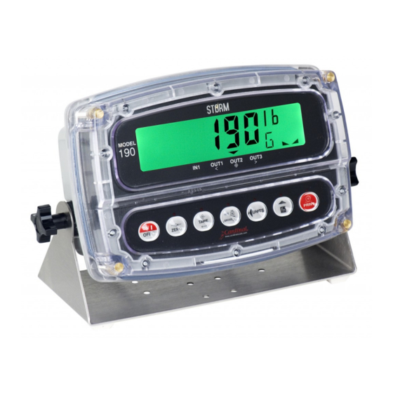
- Page 1 Model 190 Indicator Installation, Technical, and Operation Manual Includes Models 190A, 190-BP, 190DC, 190EU, 190LS, 190UK, and options BP190, 190-DAC, 190-IP, 190-RS232, 190-USB, and 190-WIFI 8400-M022-O1 Rev K Model 190 Indicator...
- Page 2 8400-M022-O1 Rev K Model 190 Indicator...
-
Page 3: Precautions
Configuration and upgrades can easily be performed in the field, while still maintaining the rigid control the most demanding installations require. This flexibility ensures the Model 190 will be able to meet your weight indicating needs for years to come. - Page 4 Please do your part by making certain that this device is properly disposed of. The symbol shown to the right indicates that this device must not be disposed of in unsorted municipal waste programs. 8400-M022-O1 Rev K Model 190 Indicator...
-
Page 5: Table Of Contents
Dual-Point without Zero (False Zero) Calibration ............. 26 Single-Point for Span Only (Last Zero) Calibration ..........27 Single-Point for Zero Only (Only Zero) Calibration ........... 28 Multi-Point Calibration ....................29 Calibration “C” Numbers ................... 31 8400-M022-O1 Rev K Model 190 Indicator... - Page 6 ERROR MESSAGES..................... 75 Before You Call Service ................... 75 Error Codes ......................76 EVENT COUNTERS ...................... 77 Accessing the Event Counters ................. 77 TEST MODE/ DIAGNOSTICS ..................79 Accessing Test Mode/Diagnostics ................79 8400-M022-O1 Rev K Model 190 Indicator...
- Page 7 AC Wiring (Detail C) ....................83 Power Supply Sub-Assembly ................... 84 P2 Wiring Detail ....................... 85 P2 Wiring Detail with 190-DAC Option Card ............85 190DC and 190LS Rear Sub-Assembly ..............86 190DC Power Supply Sub-Assembly ............... 87 190DC Wiring Detail B ..................... 88 190DC POWER OPTIONS (not shown) ..............
- Page 8 APPENDIX E – 190-WiFi Option ................108 Specifications ......................108 Onboard Status/Diagnostic LED’s ................109 Setup ........................110 Network Configuration .................... 112 Wi-Fi Operation ...................... 116 APPENDIX F – 190-DAC Option ................117 Specifications ......................117 Onboard Status/Diagnostic LED’s ................118 Setup ........................
-
Page 9: Specifications
1 to 100 samples per second, selectable Auto Zero Range: 0.5 or 1 through 9 divisions Weighing Units: Pounds, Ounces, Kilograms, Grams Keypad: Color-Coded, Capacitive Touch-type, 7 keys Standard I/O: (1) bi-directional RS232 8400-M022-O1 Rev K Model 190 Indicator... -
Page 10: Standard Features
Any application affected by vibration or movement on the scale platform can benefit from using StableSENSE ® 8400-M022-O1 Rev K Model 190 Indicator... -
Page 11: European Declaration Of Conformity
YY = last two digits of year ZZZ = sequential number The undersigned hereby declares, on behalf of Cardinal Scale Manufacturing Company of Webb City, Missouri, that the above-referenced product, to which this declaration relates, is in conformity with the provisions of: Council Directive 2006/95/EC Low Voltage Directive Test Report Number 0206-1 Cardinal Scale Mfg. -
Page 12: Precautions
CAUTION: RISK OF EXPLOSION IF BATTERY IS REPLACED BY AN INCORRECT TYPE. DISPOSE OF USED BATTERIES ACCORDING TO THE INSTRUCTIONS. ATTENTION: RISQUE D'EXPLOSION SI LA BATTERIES EST REMPLACE'E PAR UN TYPE INCORRECT. REJETEZ LES BATTERIES UTILISE'ES SELON LES INSTRUCTIONS. 8400-M022-O1 Rev K Model 190 Indicator... -
Page 13: Installation
This section is provided to assist you in obtaining such an environment. Environmental The 190 indicator meets or exceeds all certification requirements within a temperature range of 14 to 104 °F (-10 to +40 °C). To keep cooling requirements to a minimum, the indicator should be placed out of direct sunlight and to provide adequate air circulation, keep the area around the indicator clear. -
Page 14: Electrical Power
Electrical Power The 190 has been designed to operate from 100 to 240V AC @ 0.4A Max. at 50/60 Hz. Note that a special order is not required for operation at 230/240V AC. WARNING! - To avoid electrical hazard and possible damage to the indicator, DO NOT, under any circumstance, cut, remove, alter, or in any way bypass the power cord grounding prong. -
Page 15: Mounting
Mounting Before beginning the installation of your Model 190 Indicator, make certain that it has been received in good condition. Carefully remove it from the shipping carton and inspect it for any evidence of damage (such as exterior dents or scratches) that may have taken place during shipment. -
Page 16: Load Cell Connections
(with sense leads) or four wires and shield (without sense leads). 1/4” 6. Remove the 7-connector terminal block connector from P5 on the 190 mainboard. Grasp the terminal block connector and lift straight up away from the board. Figure No. 3 7. -
Page 17: Load Cell Connections With Over 30 Feet Of Cable
For scales with very low dead loads (less than 10% of the combined load cell capacity), connect the DEAD LOAD (dead load boost) jumper J3 (near the P5 terminal block). -SEN +SEN Figure No. 5 8400-M022-O1 Rev K Model 190 Indicator... -
Page 18: Serial And I/O Cable Installation
3. Remove 3" of the outer insulation jacket then remove 1/4" of insulation from each of the wires (refer to Figure No. 3). 4. Remove the 9-connector terminal block connector from P3 on the 190 mainboard. Grasp the terminal block connector and lift straight up away from the board. -
Page 19: P3 I/O Interconnection Diagram
3. Make certain no cables or wires are exposed between the rear housing and front housing assembly and then place the front housing assembly onto the rear housing. 4. Secure by tightening the 4 Captive screws loosened earlier. 8400-M022-O1 Rev K Model 190 Indicator... -
Page 20: Indicator Setup
INDICATOR SETUP Calibration Inhibit Jumper Your Model 190 indicator has been thoroughly tested and calibrated before being shipped to you. If you received the indicator attached to a scale, calibration is not necessary. If the indicator is being connected to a scale for the first time or recalibration is necessary for other reasons, proceed as indicated. -
Page 21: Calibration Data Entry
Calibration Data Entry The Model 190 uses a capacitive touch keypad that requires a “finger touch” to function. The keypad will not operate with other items such as pens, pencils, or tools. Figure No. 9 During the indicator setup and calibration process, it will be necessary to enter operational parameters via the 190 keypad. -
Page 22: Accessing Setup
Accessing Setup 1. With the 190 turned ON, press the Fn/ and UNITS/ key simultaneously. 2. Hold both keys until the display changes to SetUP. 3. Release the keys to begin setup. 4. Press the UNITS/ key to step to the beginning point of each setup section. -
Page 23: Settings
IMPORTANT! Calibration and Configuration parameters are not stored in the non-volatile memory until SETUP is exited. If power is lost while in Setup, any changes made will be lost and the 190 will revert to the previous configuration. SETUP USA= (Domestic or International) With SEtUP displayed, press the TARE ... - Page 24 4 = g (grams) NOTE: The selection for Unit2 cannot be the same as Unit1. Also, dependent upon the selection for Unit1, the interval and decimal point settings, not all unit combinations are available. 8400-M022-O1 Rev K Model 190 Indicator...
- Page 25 Otherwise, use the Fn/ key to toggle the setting and press the TARE key to save it. NOTE: In the 24-hour format, 12 is added to all times after noon, i.e., 3 PM would be 1500. td=12 td=24 12-hour clock (3PM displays 3:00) 24-hour clock (3PM displays 15:00) 8400-M022-O1 Rev K Model 190 Indicator...
- Page 26 Output not connected to common before cutoff with 1 active Preset Output not connected to common before cutoff with 2 active Presets Output not connected to common before cutoff with 3 active Presets Output not connected to common before cutoff on Checkweigher Mode 8400-M022-O1 Rev K Model 190 Indicator...
- Page 27 Battery is Installed No Battery Installed NOTE: If a battery is installed, select YES for the batt= parameter. The battery charger will be turned on automatically upon the power up of the indicator. 8400-M022-O1 Rev K Model 190 Indicator...
- Page 28 TARE key again to save it. Otherwise, use the Fn/ and UNITS/ keys to enter a new setting (0 to 255) and press the TARE key to store the new setting. 8400-M022-O1 Rev K Model 190 Indicator...
-
Page 29: Analog To Digital Filtering
TARE key again to save it. Otherwise, use the Fn/ and UNITS/ keys to enter a new setting (1 to 99) and press the TARE key to save it. 8400-M022-O1 Rev K Model 190 Indicator... - Page 30 Otherwise, use the Fn/ and UNITS/ keys to enter a new setting and press the TARE key to save the new setting. Allowable values for the stable count are 1 through 255. 8400-M022-O1 Rev K Model 190 Indicator...
-
Page 31: Filter Setting Recommendations
3. F= FILTER SETTING (1 to 99) determination: Set to desired results. 4. If stability is unacceptable with any setting of F=, reduce the sample rate and/or increase the break range, b= setting for increased filtering. 8400-M022-O1 Rev K Model 190 Indicator... -
Page 32: Calibration
Calibration The 190 indicator has six modes that can be used to perform calibration. Four of the modes require a test load or test weights, one requires the scale to be empty (and at zero) and the last uses the calibration “C” numbers from a previous calibration. -
Page 33: Dual-Point With Zero (First Zero) Calibration
Next, starting at the left and proceeding right, the dashes will disappear, after which the display will show: CAL3=. CAL3= – Last Calibration Weight The display will show CAL3=. This weight is not used. Press the UNITS/ key to skip CAL3= and advance to SetgC? prompt. 8400-M022-O1 Rev K Model 190 Indicator... -
Page 34: Dual-Point Without Zero (False Zero) Calibration
Starting at the left and proceeding right, a series of dashes will appear on the display. Next, starting at the left and proceeding right, the dashes will disappear, after which the display will show: SetgC?. 8400-M022-O1 Rev K Model 190 Indicator... -
Page 35: Single-Point For Span Only (Last Zero) Calibration
Starting at the left and proceeding right, a series of dashes will appear on the display. Next, starting at the left and proceeding right, the dashes will disappear, after which the display will show: SetgC?. 8400-M022-O1 Rev K Model 190 Indicator... -
Page 36: Single-Point For Zero Only (Only Zero) Calibration
Next, starting at the left and proceeding right, the dashes will disappear, after which the display will show: CAL2=. CAL2= – Second Calibration Weight The display will show CAL2=. This is the second of two calibration steps. Press the ZERO key. The display will advance to SetgC?. 8400-M022-O1 Rev K Model 190 Indicator... -
Page 37: Multi-Point Calibration
Starting at the left and proceeding right, a series of dashes will appear on the display. Next, starting at the left and proceeding right, the dashes will disappear, after which the display will show: CAL3=. 8400-M022-O1 Rev K Model 190 Indicator... - Page 38 Starting at the left and proceeding right, a series of dashes will appear on the display. Next, starting at the left and proceeding right, the dashes will disappear, after which the display will show: SetgC?. 8400-M022-O1 Rev K Model 190 Indicator...
-
Page 39: Calibration "C" Numbers
If the C4= value displayed is acceptable, press the TARE key again to save it. Otherwise, use Fn/ and UNITS/ keys to enter a new C4= value and press TARE key. The display will change to show: SetgC?. 8400-M022-O1 Rev K Model 190 Indicator... -
Page 40: Set Gravity Constant
Set Gravity Constant The Cardinal 190 Weight Indicator is equipped with an acceleration of gravity function which means that it can be calibrated in one location and then adjusted to match the acceleration of gravity at the location where it will be used. -
Page 41: Serial Input/Output
Otherwise, use the Fn/ key to toggle to a new setting and press the TARE key to save it. Allowable settings are: 0 = No Parity with 8 data bits 1 = Odd Parity with 7 data bits 2 = Even Parity with 7 data bits 8400-M022-O1 Rev K Model 190 Indicator... - Page 42 Otherwise, use the Fn/ key to toggle the setting and press the TARE key to save it. 0 = Continuous Output uses SMA format 1 = Continuous Output uses Cardinal Scoreboard format SMA Continuous Output Format If SMA is selected, data will be transmitted in the following format: <lf><s><r><n><m><f><xxxxxx.xxx><uuu><cr>...
- Page 43 = Carriage Return (hex 0D) Operation Commands A connection to the 190 Serial Port RXD serial input can be used to send commands to the indicator. A description of the available commands is described in the section, ASCII Commands.
-
Page 44: Print Tab Settings
TARE key again to save it. Otherwise, use the Fn/ and UNITS/ keys to enter a new location and press the TARE key to save it. 8400-M022-O1 Rev K Model 190 Indicator... - Page 45 TARE key again to save it. Otherwise, use the Fn/ and UNITS/ keys to enter a new location and press the TARE key to save it. 8400-M022-O1 Rev K Model 190 Indicator...
- Page 46 TARE key again to save it. Otherwise, use the Fn/ and UNITS/ keys to enter a new number of End-Of-Print linefeeds and press the TARE key to save it. Allowable settings are: 0 through 99 8400-M022-O1 Rev K Model 190 Indicator...
-
Page 47: Fine Span Adjustment
Press the Fn/ key to increase the span by 0.5 division OR press the UNITS/ key to decrease the span by 0.5 division. Press the TARE key to exit the Fine Span Adjustment and advance to the Hires? prompt. 8400-M022-O1 Rev K Model 190 Indicator... -
Page 48: Display High Resolution Weight
Press the Fn/ key to increase the span by 0.1 division OR press the UNITS/ key to decrease the span by 0.1 division. Press the TARE key to exit the Display High Resolution Weight and advance to the LoCoUt? prompt. 8400-M022-O1 Rev K Model 190 Indicator... -
Page 49: Key Lockout Feature
TARE key again to save it. Otherwise, use the Fn/ key to toggle the setting and press the TARE key to save it. UnLoCd LoCD Key is Unlocked (Enabled) Key is Locked (Disabled) 8400-M022-O1 Rev K Model 190 Indicator... - Page 50 "LoCd" and then prompt the operator to press the following keys in this order: PRINT, ZERO, Fn/, TARE , UNITS/, NET/GROSS If no key is pressed or the keys are pressed in the wrong order, the indicator will turn off. 8400-M022-O1 Rev K Model 190 Indicator...
-
Page 51: Options Setup
TARE key to save it. Allowable settings are: 12 = 1200 Baud 24 = 2400 Baud 48 = 4800 Baud 96 = 9600 Baud 19 = 19.2k Baud 38 = 38.4k Baud 76 = 76.8k Baud 8400-M022-O1 Rev K Model 190 Indicator... - Page 52 Otherwise, use the Fn/ key to toggle the setting and press the TARE key to save it. 0 = Continuous Output uses SMA format 1 = Continuous Output uses Cardinal Scoreboard format NOTE: Refer to the CONT1= Continuous Output on Serial Interface, tYPE= parameter for a description of output formats.
-
Page 53: Function Setup
TARE key again to save it. Otherwise, use the Fn/ key to toggle the setting and press the TARE key to save it. Time and Date is Enabled Time and Date is Disabled 8400-M022-O1 Rev K Model 190 Indicator... - Page 54 TARE key again to save it. Otherwise, use the Fn/ key to toggle the setting and press the TARE key to save it. Weight Accumulation Weight Accumulation Function is Enabled Function is Disabled 8400-M022-O1 Rev K Model 190 Indicator...
-
Page 55: Display Backlight Color Setup
Otherwise, use the Fn/ key to toggle to a new setting and press the TARE key to save it. Allowable settings are: 0 = No Backlight 1 = Red Backlight 2 = Green Backlight 3 = Yellow Backlight 4 = Blue Backlight 5 = Pink Backlight 8400-M022-O1 Rev K Model 190 Indicator... - Page 56 Otherwise, use the Fn/ key to toggle to a new setting and press the TARE key to save it. Allowable settings are: 0 = No Backlight 1 = Red Backlight 2 = Green Backlight 3 = Yellow Backlight 4 = Blue Backlight 5 = Pink Backlight 8400-M022-O1 Rev K Model 190 Indicator...
-
Page 57: Keypad
KEYPAD Standard Key Functions The Model 190 is equipped with a 7-key Capacitive Touch keypad. The keypad is used to enter commands and data into the indicator. This section describes each key along with its normal function. It is helpful to refer to the actual indicator while reading this section. - Page 58 ("unit1", “unit2”, and "unit3") are selected in setup. The available units include pounds, ounces, kilograms, and grams. During setup, the UNITS/ key is used to advance the cursor left to the next position when inputting setup parameters. 8400-M022-O1 Rev K Model 190 Indicator...
- Page 59 Gross weight, or Net weight to the associated accumulator and send print ticket data to the serial interface selected during setup (see Port=). NOTE: The indicator will not respond to pressing the PRINT key unless the weight display is stable. 8400-M022-O1 Rev K Model 190 Indicator...
-
Page 60: Fn/ Key Functions
Live Weight X will be 1 if enabled, 0 if disabled Weight X will be 1 if enabled, 0 if disabled ACCU Accumulation Backlight Color Backlight Colors for normal operation and Colors Checkweigher results 8400-M022-O1 Rev K Model 190 Indicator... -
Page 61: Fn/ Key Combination Features
Refer to the Operation, Ticket Format Selection for details. This key combination is also used to enter the Preset Weight Comparators “PWC” weight values. Refer to the Operation, Preset Weight Comparators section for details. 8400-M022-O1 Rev K Model 190 Indicator... -
Page 62: Annunicators
ANNUNICATORS The Model 190 is equipped with annunciators that are turned on to indicate that the display is in the mode corresponding to the annunciator label or that the status indicated by the label is active. This section describes each annunciator. Refer to the illustration below for the location of the annunciators. - Page 63 This annunciator is also used to indicate that preset 3 is active. Note that this annunciator is active only when the Checkweigher feature or the preset feature has been enabled. Refer to the d oUt parameter in Setup. 8400-M022-O1 Rev K Model 190 Indicator...
-
Page 64: Battery Status
NOTE: When the indicator is connected to an external power supply and is charging the battery, the charge level status bars will scroll. Also, as the battery approaches full discharge, the outline of the battery will start to flash. 8400-M022-O1 Rev K Model 190 Indicator... -
Page 65: Indicator Setup Review
INDICATOR SETUP REVIEW The 190 indicator allows several operational parameters to be reviewed and changed without breaking the calibration seal. Accessing Setup Review With the indicator ON, press the Fn/ key and then the ZERO key. The display will change to show td= (the prompt for selection of a 12 or 24-hour clock). - Page 66 Enable or Disable Continuous Output to the Option Port Cont2= type= If Opt=1 and Cont2=YES (Select Continuous Output Format, SMA or Cardinal Scoreboard) Select Field Bus Option Baud Rate when Opt= 2 baUd= Select Field Bus Option MAC Address when Opt= 2...
-
Page 67: Operation
The 190 includes support for visual tickets. Visual tickets are designed by the PC-based programs Visual Print or nControl and then downloaded to the indicator. The 190 allows one programmable format in addition to the standard print tab settings format. Press the Fn/ key then the PRINT key. -
Page 68: Preset Weight Comparators
Preset Weight Comparators The Model 190 has three (3) outputs, which can be configured during setup to perform as Preset Weight Comparators “PWC”. The output state of each PWC (before reaching the preset weight) is defined in the section SETUP, d out= (Digital Output) parameter. -
Page 69: Hold Function
Press the PRINT key to print the held reading. Press the NET/GROSS, ZERO, TARE , or UNITS/ key to release the hold and return to the weight display. 8400-M022-O1 Rev K Model 190 Indicator... -
Page 70: Count Function
To change the average piece weight, press the Fn/ key a second time, and the Add= 5 prompt will be displayed. To quit the sampling process without changing the average piece weight, set the sample size to 0 and press the TARE key. 8400-M022-O1 Rev K Model 190 Indicator... -
Page 71: Time And Date Functions
When the correct date is displayed, press the TARE key to save it. Repeatedly press the TARE key to step through the remaining function prompts until the indicator returns to the weight display. 8400-M022-O1 Rev K Model 190 Indicator... -
Page 72: Peak Hold Function
To display the peak value, momentarily press the Fn/ key. To zero the peak value, make sure there is no load on the scale and press the ZERO key. Press the NET/GROSS key to return to the weight display. 8400-M022-O1 Rev K Model 190 Indicator... -
Page 73: Checkweigher
Checkweigher The Model 190 has logic level outputs that can be used to control peripheral devices used to signal when the weight is within preset limits. The output state of the Checkweigher (before reaching the preset weight) is defined in the section SETUP, the d out= (Digital Output) parameter. - Page 74 When the displayed weight is within the range from minimum acceptable weight to maximum acceptable weight, the arrow over OUT2 ⊕ (the ACCEPT annunciator) will turn on and the display will change to the color selected in the section, Display Backlight Color Setup. 8400-M022-O1 Rev K Model 190 Indicator...
-
Page 75: Live Weight Function
Load the scale platform. When a stable value has been reached, the Hold annunciator will be on steadily and the display will lock. Press the NET/GROSS key to return to the weight display. 8400-M022-O1 Rev K Model 190 Indicator... -
Page 76: Accumulated Weight Function
Press the TARE key to display the Gross accumulator again. Press the ZERO key to clear the displayed accumulator. Press the NET/GROSS key to return to the normal weight display. 8400-M022-O1 Rev K Model 190 Indicator... -
Page 77: Touch Key Lock Out Function
Touch Key Lock Out Function The 190 firmware provides a means for locking out the capacitive touch keys. When the keys are locked out, any activation of the keys, whether intentional or accidental, will be ignored. NOTE: This function is available in firmware version 1.0.13 or newer. -
Page 78: Ascii Commands
ASCII Commands The Model 190 indicator will respond to ASCII commands when input to the 190’s internal serial port, the 190-RS232 option card, the 190-IP option card, and the 190-WiFi option card. Note that for the indicator to respond to the ASCII commands described below, the internal serial port and the option cards must be set to “Weight-On-Demand”... - Page 79 Request Displayed Weight Command (SMA Format) The wireless device sends: <LF>W<CR> The 190 will respond with displayed weight in SMA format: <LF><s><r><n><m><f><xxxxxxx.xxx><uuu><CR> where: <LF> line feed (hex 0A) <s> scale status Z = center of zero O = over capacity...
- Page 80 Request Scale to Zero Command The wireless device sends: <LF>Z<CR> The 190 will attempt to zero the scale and respond with weight in SMA format. Scale status will indicate if the attempt to zero was unsuccessful. Request Scale to Tare Command The wireless device sends: <LF>T<CR>...
- Page 81 About Scale Scroll Command The wireless device sends: <LF>B<CR> The 190 will respond with the following (NOTE: The command must be repeated for each response): <LF>MFG:Cardinal Scale Mfg. Co.<CR> <LF>MOD:190<CR> <LF>REV:n.n.nn/1.1<CR> <LF>END:<CR> NOTE: n.n.nn will be the version number for the 190 firmware.
- Page 82 Abort Command The wireless device sends: <ESC> (hex 1B) The 190 will clear any pending commands. The 190 will not send a response to this command. Unrecognized Command Response If the 190 receives a command it does not recognize it will respond with <LF>?<CR>...
-
Page 83: Error Messages
ERROR MESSAGES Before You Call Service The Cardinal 190 Weight Indicator has been designed to provide you with years of trouble-free operation. However, should you experience a problem, please refer to the troubleshooting guide below before you call for service. The following describes several types of symptoms along with suggested remedies. -
Page 84: Error Codes
The Cardinal 190 Weight Indicator is equipped with software that indicates when an error in the operation takes place. The following lists the error codes displayed by the 190 along with their meaning. Should you encounter an error code, please refer to this list for the cause. -
Page 85: Event Counters
The Cardinal Model 190 Weight Indicator has been designed with a Category 1 Event Counter type of security seal. The 190 will display two event counters that increment when a change is made to features that are required by NTEP or OIML to be sealed. One counter is designated for calibration parameters and one is designated for configuration changes as required in NCWM Publication 14, 2007. - Page 86 Decimal Point Precision Capacity Weighing Units 2 (Secondary Units) Unit2 Zero Tracking Range 4% Zero Limit Power Up Zero Digital Filter Number dFLt Filter Level Amount Filter Break Range Sample Rate Motion Range Stable Count 8400-M022-O1 Rev K Model 190 Indicator...
-
Page 87: Test Mode/ Diagnostics
TEST MODE/ DIAGNOSTICS The Cardinal Model 190 Weight Indicator has a comprehensive diagnostic feature that can allow it to self-diagnose a problem. After displaying the model number, software revision, and performing a display test, the indicator will enter the diagnostics mode. -
Page 88: Parts Identification
PARTS IDENTIFICATION Front Sub-Assembly 8400-M022-O1 Rev K Model 190 Indicator... - Page 89 PCB Controller Terminal Block Connectors QTY. PART NUMBER DESCRIPTION 6610-1552 P2 – 5-PIN POWER TERMINAL BLOCK CONNECTOR 6610-1554 P5 – 7-PIN LOAD CELL TERMINAL BLOCK CONNECTOR 6610-1556 P3 – 9-PIN I/O TERMINAL BLOCK CONNECTOR Not shown. 8400-M022-O1 Rev K Model 190 Indicator...
-
Page 90: Rear Sub-Assembly
8200-B104-08 LABEL: 205-210 TERM. BLOCK 8400-B020-08 O-RING, 190 8400-D012-08 PLASTIC BACK, 190 8510-C346-0I LABEL CAUTION HIGH VOLTAGE SCW FILLISTER, MACHINE-SCW 10-32X1.5. WITH 8400-0150-08 UNDERCUT THREADS SS 8400-D012-08 MODIFIED PLASTIC BACK, 190 (FOR 190A) 8400-M022-O1 Rev K Model 190 Indicator... -
Page 91: Ac Wiring (Detail C)
ITEM NO. QTY. PART NUMBER DESCRIPTION 6540-0332 KNOB, ENCLOSURE 1.25 DIA W/10-32 X 3/4 STUD PLUG, HOLE 0.343” X 0.187” X 1” LG, SILICONE 6540-1104 RUBBER 8400-B001-08 RUBBER GIMBAL WASHER AC Wiring (Detail C) 8400-M022-O1 Rev K Model 190 Indicator... -
Page 92: Power Supply Sub-Assembly
WASHER LOCK INT TOOTH #4 TYPE A Z-PL 6680-0138 SPACER #6 X .187 NYLON 6680-1107 SPACER #4-40 X .750 3/16 HEX ALU. Z/P 8400-B017-0A 190 AC POWER CABLE (SEE AC WIRING DETAIL C) 8400-B018-0A DC POWER CABLE, 190 8400-B019-08 POWER SUPPLY, 190 8400-C005-08 POWER SUPPLY COVER, 190 8400-M022-O1 Rev K ... -
Page 93: P2 Wiring Detail
P2 Wiring Detail DETAIL B P2 Wiring Detail with 190-DAC Option Card ITEM NO. QTY. PART NUMBER DESCRIPTION 8400-C031-0A PCB, 190-DAC OPTION CARD 0.5 ft 6980-0151 WIRE, 24 GA, RED (6” LONG) 0.5 ft 6980-0150 WIRE, 24 GA, BLACK (6” LONG) -
Page 94: 190Dc And 190Ls Rear Sub-Assembly
MODIFIED PLASTIC BACK, 190 (FOR 190A) SCW FILLISTER, MACHINE-SCW 10-32X1.5, WITH 8400-0150-08 UNDERCUT THREADS SS 1938-0050-0A CABLE, 190 LOAD CELL PIGTAIL (190LS ONLY) 6610-5033 CABLE TIE, LARGE 8” (190LS ONLY) 6800-1072 BATTERY, LI-ION, 7.4V, 2600 mAH (190LS ONLY) 8400-M022-O1 Rev K Model 190 Indicator... -
Page 95: 190Dc Power Supply Sub-Assembly
WASHER LOCK INT TOOTH #4 TYPE A Z-PL 6680-0138 SPACER #6 X .187 NYLON 6680-1107 SPACER #4-40X.750 3/16 HEX ALU. Z/P 8400-B017-0A 190 AC POWER CABLE (SEE 190DC WIRING DETAIL B) 8400-B018-0A DC POWER CABLE, 190 8400-C005-08 POWER SUPPLY COVER, 190 8400-C026-0A POWER SUPPLY, 190DC 8400-M022-O1 Rev K ... -
Page 96: 190Dc Wiring Detail B
190DC POWER MATING CONNECTOR, 6 FT CABLE AND BATTERY TERMINAL EYELETS 190DC12 190DC POWER MATING CONNECTOR, 12 FT CABLE AND BATTERY TERMINAL EYELETS 190DC18 190DC POWER MATING CONNECTOR, 18 FT CABLE AND BATTERY TERMINAL EYELETS 190DCMATE 190DC POWER MATING CONNECTOR 8400-M022-O1 Rev K Model 190 Indicator... - Page 97 8400-M022-O1 Rev K Model 190 Indicator...
-
Page 98: Appendix A - Bp190 Optional Battery Pack
DO NOT charge the battery above 40 C. Lithium-ion does not need to be fully charged; a partial charge is acceptable. The battery does not need to be fully discharged between charging cycles. 8400-M022-O1 Rev K Model 190 Indicator... -
Page 99: Installing The Bp190
7. Secure battery pack to power supply cover with cable ties. 8. Insert 5-connector terminal block removed in step 2 into P2 on 190 main board. 9. Make certain no cables or wires are exposed between the rear housing and front housing assembly and then place the front housing assembly onto the rear housing. - Page 100 Battery Pack Cable Ties Connected Together See Step 5 Note and Images Below. CORRECT! WRONG! Position Cable Ties Connection on Do Not Position Cable Ties Top of Batteries. Connection on Front of Batteries. 8400-M022-O1 Rev K Model 190 Indicator...
-
Page 101: Appendix B - Model 190A
X,Y (Digital Output) setting enables the Axle Weighing Mode. NOTE: The Model 190 cannot be upgraded to a Model 190A in the field. It must be returned to the factory to perform the upgrade. When the d oUt= parameter is set to 5, the following prompts will be enabled:... - Page 102 TARE key to save it. Allowable values for the total delay are 1 to 99 seconds. NOTE: The Total Delay timer will start after the Stoplight Delay timer expires. 8400-M022-O1 Rev K Model 190 Indicator...
-
Page 103: Standard Axle Weighing Operation
5. When the display shows that the weight is stable, press the PRINT key to record the weight. 6. Have the vehicle driven forward until the next set of wheels are centered on the axle load weighers. 7. Press the PRINT key to record the weight. 8400-M022-O1 Rev K Model 190 Indicator... - Page 104 This may be repeated as many times as desired as long as the indicator is not turned off or another axle weight recorded. As soon as the first axle weight of the next vehicle is printed, the axle weights of the previous vehicle are cleared. 8400-M022-O1 Rev K Model 190 Indicator...
-
Page 105: Auto Axle Weighing Operation
The traffic light will turn red. The Gross weight for that axle will be displayed. 3. After the motion on the scale stops, the printer will print the weight on the scale and add the weight to the total accumulator. The Printd message will be displayed on the 190 display. -
Page 106: Wiring
NOTE: Refer to the CONT1= Continuous Output on Serial Interface, tYPE= parameter section for a description of output formats 0 and 1. Cardinal SB500 with traffic control Continuous Output Format If Cardinal SB500 with traffic control is selected, the data will be transmitted in the following format: %NDDDDDDDDDT<CR>... -
Page 107: Scoreboard Interconnections
Scoreboard Interconnections Serial Option Card P4 Wiring RS232 Wiring 20mA Current Loop (Passive) 8400-M022-O1 Rev K Model 190 Indicator... -
Page 108: Appendix C - 190-Rs232 Option
APPENDIX C – 190-RS232 Option Operation A connection to the 190-RS232 option card RXD serial input can be used to send commands to the 190. A description of the available commands is described in the ASCII Commands section. Specifications Function:... -
Page 109: Setup
TARE key to save it. Allowable settings are: 12 = 1200 Baud 24 = 2400 Baud 48 = 4800 Baud 96 = 9600 Baud 19 = 19.2k Baud 38 = 38.4k Baud 76 = 76.8k Baud 8400-M022-O1 Rev K Model 190 Indicator... - Page 110 0 = Continuous Output uses SMA format 1 = Continuous Output uses Cardinal Scoreboard format 2 = Continuous Output uses Cardinal SB500 with traffic control format NOTE: Refer to the CONT1= Continuous Output on Serial Interface, tYPE= parameter section for a description of output formats 0 and 1.
- Page 111 Cardinal SB500 with traffic control Continuous Output Format If Cardinal SB500 with traffic control is selected, the data will be transmitted in the following format: %NDDDDDDDDDT<CR> where: = Panel number for a daisy chain configuration = Byte of data to display at a respective location on the scoreboard = Control character for the traffic light.
-
Page 112: Appendix D - 190-Ip Option
(12 MIPS at 48 MHz, 22 MIPS at 88 MHz) E-mail client capability Password protection Status/diagnostic LEDs Onboard Status/Diagnostic LED’s The 190-IP option card contains three (3) LEDs to indicate the communication status of the Ethernet TCP/IP connection. LED Indication Description Indicates data transferred from the 190... -
Page 113: Setup
Otherwise, use the Fn/ key to toggle the parity setting to 0 (No Parity with 8 data bits) and press the TARE key to save it. NOTE: The default parity is 0 (No Parity with 8 data bits) and should not be changed. 8400-M022-O1 Rev K Model 190 Indicator... -
Page 114: Ethernet Cable Installation
Resource Type > Software > Lantronix DeviceInstaller for Cardinal IP Devices. 190-IP Operation A client TCP connection to the 190-IP IP address at its listening port, 10001, can be used to send commands to the 190. A description of the available commands is described in the ASCII Commands section. -
Page 115: Xport Connector Status Led's
100BASE-T Full Duplex Link Blinking Green 100BASE-T Full Duplex; Activity Solid Amber 10BASE-T Half Duplex Link Blinking Amber 10BASE-T Half Duplex; Activity Solid Green 10BASE-T Full Duplex Link Blinking Green 10BASE-T Full Duplex; Activity 8400-M022-O1 Rev K Model 190 Indicator... -
Page 116: Appendix E - 190-Wifi Option
APPENDIX E – 190-WiFi Option The 190-WiFi Option is used to connect the 190 digital weight indicator to IEEE 802.11b/g wireless local area networks (wireless LAN). When the indicator is powered on, the Wi-Fi option card will connect to a wireless LAN matching the configuration stored in the option card. -
Page 117: Onboard Status/Diagnostic Led's
Onboard Status/Diagnostic LED’s The 190-WiFi option card contains four (4) LEDs to indicate the communication status of the wireless connection. LED Indication Description DISC This LED indicates that Discovery Mode is active on the 190- WIFI. Discovery Mode affects whether the 190-WIFI can see (find) computers and devices on the network and whether other computers on the network can see the 190-WIFI. -
Page 118: Setup
Otherwise, use the Fn/ key to toggle the parity setting to 0 (No Parity with 8 data bits) and press the TARE key to save it. NOTE: The default parity is 0 (No Parity with 8 data bits) and should not be changed. 8400-M022-O1 Rev K Model 190 Indicator... - Page 119 0 = Continuous Output uses SMA format 1 = Continuous Output uses Cardinal Scoreboard format 2 = Continuous Output uses Cardinal SB500 with traffic control format NOTE: Refer to the CONT1= Continuous Output on Serial Interface, tYPE= parameter section for a description of output formats 0 and 1.
-
Page 120: Network Configuration
From the initial factory settings, the 190-WIFI will appear as a wireless access point with the name “190WIFI”. To connect to 190-WIFI for initial setup, you will need to connect to it as a wireless access point using a wireless device such as a laptop, PC, tablet, or smartphone. - Page 121 Web Configuration Parameter Descriptions – Access Point The configuration web page in the 190-WIFI module allows the module to be configured as either an access point or to connect to an existing network. To accomplish this, a new parameter has been added on the web page “Network Mode”.
- Page 122 This parameter allows the 190-WIFI module to be configured as either an access point, or to connect to an existing network. To set up the 190-WIFI module as an access point, set the mode to “Server (SoftAP). Access Point SSID Enter the SSID of the access point you wish to connect to here.
- Page 123 Access Point SSID Enter the SSID of the access point you wish to connect to here. If no access point exists with the SSID that is entered, then the 190-WIFI module will attempt to start an access point with the entered SSID.
-
Page 124: Wi-Fi Operation
DEFAULT jumper to restore the network to a known configuration. Wi-Fi Operation A connection to the 190-WIFI option card can be used to send commands to the 190. A description of the available commands is described in the ASCII Commands section. -
Page 125: Appendix F - 190-Dac Option
APPENDIX F – 190-DAC OPTION The 190-DAC is an option card for the 190 that outputs an analog 0-10V or 0-24mA. The user can control the output voltage or current using the DAC interface in the 190. The DAC has sense jumpers that allow the user to connect the 190-DAC card voltage or current lines long distances. -
Page 126: Onboard Status/Diagnostic Led's
Onboard Status/Diagnostic LED’s The 190-DAC option card contains four (4) LEDs to indicate run time status and errors to the user. LED Indication Description DC/DC Power Voltage is in tolerance 9V ± 5% and isolated DAC is powered. NOTE: The DC/DC Power (D1) LED will be on continuously when the DAC is powered. -
Page 127: Setup
Allowable values are: 0 = 4-20 ma 1 = 0-20 ma 2 = 0-24 ma 3 = 0-10 volts 4 = 0-5 volts 5 = -10 to +10 volts 6 = -5 to +5 volts 8400-M022-O1 Rev K Model 190 Indicator... - Page 128 NOTE: If one of the current output ranges is selected, set oUt= to: 4-20 ma: 10 X (max_current – 4) / 16 0-20 ma: 10 X (max_current)/20 0-24 ma: 10 X (max_current)/24 +1-5 Set OUT = 5.00 8400-M022-O1 Rev K Model 190 Indicator...
-
Page 129: Dac Wiring
DAC Option Card P1 Power Connection To power the DAC option card, connect P1 on the DAC (Pin +9V and GND) to connector P2 of 190 Main Board (Pin +9V and GND). DAC Option Card P3 Analog Out Connections Terminal... -
Page 130: Appendix G - 190-Usb Option
APPENDIX G – 190-USB Option Features The 190-USB Option is a standard full-speed (12Mbps) USB 2.0 device (or upstream) port. It can be connected to a USB 2.0 host, with the Cardinal Scale 8200-B512-0A USB CABLE, to be used as a serial I/O port. -
Page 131: Setup
Otherwise, use the Fn/ key to toggle the parity setting to 0 (No Parity with 8 data bits) and press the TARE key to save it. NOTE: The default parity is 0 (No Parity with 8 data bits) and should not be changed. 8400-M022-O1 Rev K Model 190 Indicator... -
Page 132: 190-Usb Operation
0 and 1. 190-USB Operation A connection to the 190-USB option card can be used to send commands to the 190. A description of the available commands is described in the ASCII Commands section. - Page 133 STATEMENT OF LIMITED WARRANTY WARRANTY TERMS Cardinal Scale Manufacturing Company warrants the equipment we manufacture against defects in material and workmanship. The length and terms and conditions of these warranties vary with the type of product and are summarized below:...
- Page 134 This warranty sets forth the extent of our liability for breach of any warranty or deficiency in connection with the sale or use of our product. Cardinal will not be liable for consequential damages of any nature, including but not limited to loss of profit, delays or expenses, whether based on tort or contract.
- Page 135 8400-M022-O1 Rev K Model 190 Indicator...
- Page 136 Cardinal Scale Mfg. Co. 102 E. Daugherty, Webb City, MO 64870 USA Ph: 417-673-4631 or 1-800-641-2008 Fax: 417-673-2153 www.cardinalscale.com Technical Support: 1-866-254-8261 Printed in USA E-mail: tech@cardet.com 8400-M022-O1 Rev K 04/21 8400-M022-O1 Rev K Model 190 Indicator...
Need help?
Do you have a question about the 190 and is the answer not in the manual?
Questions and answers