Sign In
Upload
Download
Table of Contents
Contents
Add to my manuals
Delete from my manuals
Share
URL of this page:
HTML Link:
Bookmark this page
Add
Manual will be automatically added to "My Manuals"
Print this page
×
Bookmark added
×
Added to my manuals
Manuals
Brands
Cardinal Manuals
Measuring Instruments
212 Series
Installation, technical and operation manual
Cardinal 212 Series Installation, Technical And Operation Manual
Hide thumbs
1
2
3
4
Table Of Contents
5
6
7
8
9
10
11
12
13
14
15
16
17
18
19
20
21
22
23
24
25
26
27
28
29
30
31
32
33
34
35
36
37
38
39
40
41
42
43
44
45
46
47
48
49
50
51
52
53
54
55
56
57
58
59
60
61
62
63
64
65
66
67
68
69
70
71
72
73
74
75
76
77
78
79
80
81
82
83
84
85
86
87
88
89
90
91
92
93
94
95
96
97
98
99
100
101
102
103
104
105
106
107
108
109
110
111
112
113
114
115
116
117
118
119
120
121
122
123
124
125
126
127
128
129
130
131
132
133
134
135
136
137
138
139
140
141
142
143
144
145
146
147
148
149
150
151
152
153
154
page
of
154
Go
/
154
Contents
Table of Contents
Troubleshooting
Bookmarks
Table of Contents
Table of Contents
1 Overview
Specifications
Model Number Description
Standard Features
Options
Accessories
Precautions
Static Electricity
Key Descriptions
Annunicators
2 Getting Started
Installation
Site Preparation Requirements
Environmental
Electrical Power
Transient Suppression
Mounting the 212/212X
Installing the Wall Bracket
Cable Connections
DC Power Cable Connection
Scale Cable Connections
Serial and I/O Cable Connection
AGSIO (Serial/Dio Mating Connector Cable)
Optically Isolated Inputs
Optically Isolated Outputs
Optional DC Output Relay Board
Main PCB (Printed Circuit Board)
Main PCB Jumpers
Indicator Setup
Setup Data Entry
Quick Calibration
Quick Calibration Weigh Bar Table
Full Setup and Configuration
Settings
Analog to Digital Filtering
Filter Setting Recommendations
Calibration
Weigh Bar Table (Calibration Mode Selection 1)
Enter Load Cell Specs (Calibration Mode Selection 2)
Other Calibration Modes (Calibration Mode Selection 3)
Dual-Point with Zero (First Zero) Calibration
Dual-Point Without Zero (False Zero) Calibration
Single-Point for Span Only (Last Zero) Calibration
Single-Point for Zero Only (Only Zero) Calibration
Calibration "C" Numbers
Serial Input/Output
Print Tab Settings
Fine Span Adjustment
Display High Resolution Weight
Key Lock out Function
Storing Indicator Defaults
Restoring Indicator Defaults
Indicator Setup Review
Accessing Setup Review
Indicator Operational Setup Review
Accessing and Navigating the Operational Setup Review
3 Operation
Standard Weighing
Subtractive Weighing
Auto-Hold for Animal Weighing
Preset Weight Comparator (PWC)
Digital Fill Control (DFC)
Specified Target Weight DFC
Simple DFC (Simple-Fill)
Box-Tracker DFC Mode (Box Fill)
Plot-Tracker DFC Mode (Plot Fill)
Using Memory/ID Storage
4 Service
Troubleshooting
Error and Status Messages
Care and Maintenance
Parts
Rear Sub-Assembly
Front Sub-Assembly
Final Assembly
Advertisement
Quick Links
1
Quick Calibration
2
Calibration
3
Troubleshooting
4
Error and Status Messages
Download this manual
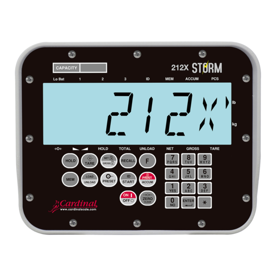
Model 212/212X
Indicator
Installation, Technical
and Operation Manual
Table of
Contents
Previous
Page
Next
Page
1
2
3
4
5
Advertisement
Table of Contents
Need help?
Do you have a question about the 212 Series and is the answer not in the manual?
Ask a question
Questions and answers
Related Manuals for Cardinal 212 Series
Measuring Instruments Cardinal 225 Installation, Set-Up And Operation Manual
Check weigher for the 225 weight indicator (16 pages)
Measuring Instruments Cardinal 200 Series Installation, Technical And Operation Manual
Weight indicating instrument (47 pages)
Measuring Instruments Cardinal 212X Series Installation, Technical And Operation Manual
(154 pages)
Measuring Instruments Cardinal 225D Instructions Manual
(18 pages)
Measuring Instruments Cardinal 190 Installation, Technical And Operation Manual
(136 pages)
Measuring Instruments Cardinal 825 Gen2 Installation And Technical Manual
Desktop weight indicator (198 pages)
This manual is also suitable for:
212x series
212-1s
212-4s
212x-1s
212x-4s
Table of Contents
Print
Rename the bookmark
Delete bookmark?
Delete from my manuals?
Login
Sign In
OR
Sign in with Facebook
Sign in with Google
Upload manual
Upload from disk
Upload from URL


Need help?
Do you have a question about the 212 Series and is the answer not in the manual?
Questions and answers