Table of Contents

Related Manuals for Cardinal 200 Series


Summary of Contents for Cardinal 200 Series
- Page 1 200 SERIES WEIGHT INDICATING INSTRUMENT MODELS 200, 205 and 210 TECHNICAL and OPERATION MANUAL PO BOX 151 • WEBB CITY, MO 64870 8200-M024-O1 Rev D Printed in USA PH (417) 673-4631 • FAX (417) 673-5001 04/01 http://www.cardinalscale.com...
-
Page 2: Table Of Contents
TABLE OF CONTENTS STATIC ELECTRICITY PRECAUTION - - - - - - - - - - - - - - - - - - - - - - - - - - - - - - - - - - Page 2 FCC COMPLIANCE STATEMENT - - - - - - - - - - - - - - - - - - - - - - - - - - - - - - - - - - - - - Page 2 SPECIFICATIONS - - - - - - - - - - - - - - - - - - - - - - - - - - - - - - - - - - - - - - - - - - - - - - - - Page 3... -
Page 3: Static Electricity Precaution
STATIC ELECTRICITY PRECAUTION CAUTION! This device contains static sensitive circuit cards and components. Improper handling of these devices or printed circuit cards can result in damage to or destruction of the component or card. Such actual and/or consequential damage IS NOT covered under warranty and is the responsibility of the device owner. -
Page 4: Specifications
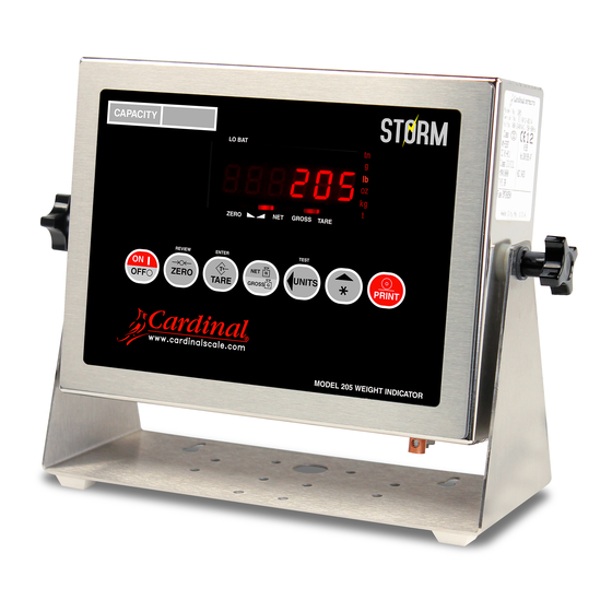
SPECIFICATIONS Power Requirements: 90 to 264 VAC (50/60 Hz) at 0.4A Battery Operation: ( Models 205 and 210 only ) CAM-350 Type 12 volt 2000 mAh (2.0 Ah) Enclosure Type, Size: Model 200 - Panel Mount, NEMA 12/IP52: 5 11/16"W x 2 13/16"H x 7 7/8"D (144mm W x 72mm H x 200mm D) Models 205/210 v- NEMA 4X/IP66: 9 3/16"W x 7 1/2"H x 3 1/8"D (233mm W x 191mm H x 79mm D) Weight: 8.2lbs - (9.6lb with battery) -
Page 5: Site Preparation Requirements
This section is provided to assist you in obtaining such an environment. Electrical Power The 200 Series Indicators are designed to operate from 90 to 264 VAC at 50/60 Hz. Note that a special order is not required for operation at 230 VAC. -
Page 6: Installation
INSTALLATION Before beginning installation of your Model 200 Series Weight Indicating Instrument, make certain that the instrument has been received in good condition. Carefully remove the instrument from the shipping carton and inspect it for any evidence of damage (such as exterior dents or scratches) that may have taken place during shipment. -
Page 7: Models 205 And 210
INSTALLATION, Cont. MODELS 205 AND 210 Remove the 12 screws securing the back panel to the main housing, then loosen the bottom-left cable gland connector for the load cell. This 115 to 230 VAC gland connector is located on the rear panel of 0.4 Amp max. -
Page 8: Serial I/O Cable Installation
SERIAL I/O CABLE INSTALLATION The 200 Series may be connected to a printer to record weight and associated data or it may be connected to a remote display or even to a computer for transmission of weight data. The weight data may be transmitted on demand (pressing the PRINT key or on receipt of a command from the computer). -
Page 9: Models 205 And 210
INSTALLATION, Cont. MODEL 205/210 1. Loosen the cable gland connector(s) for the serial cable. The gland connector(s) for the serial data are located on the rear panel of the enclosure. Refer to Figure No. 4 for an illustration of the gland connector layout. 2. -
Page 10: Relay Board
INSTALLATION, Cont. RELAY BOARD - (Optional, Model 210 Only) The relay board (Cardinal p/n 8539-C062-0A) is mounted in the RB4-F external junction box for use with the 210 Indicator. Connect the devices to be controlled as shown in Figure No. 8. -
Page 11: Keypad Functions - Models 200 And 205
KEYPAD FUNCTIONS - MODEL 200 and 205 The Model 200 and 205 are equipped with a 7-key keypad. The keypad is used to enter commands and data into the instrument. This section describes each key along with its normal function. It is helpful to refer to the actual instrument while reading this section. The membrane keypad is not to be operated with pointed objects (pencils, pens, fingernails, etc). - Page 12 If displaying net weight, the gross, tare, and net weights are printed. The 200 Series includes support for Visual Print. Visual Print is a PC based program that designs a ticket then downloads the ticket information to the 10:19 23/08/2000 indicator.
-
Page 13: Annunciators - Models 200 And 205
KEYPAD FUNCTIONS - MODELS 200 and 205, Cont. ASTERISK, UNITS KEY This combination will enter the Test mode. The Test mode is used to conduct a test of all display elements. The test consists of 5 cycles, each lasting about one second: 1. -
Page 14: Keypad Functions - Model 210
ANNUNCIATORS - MODELS 200 and 205, Cont. The lb (pound) annunciator is located to the left of the weight display and is turned on to indicate that the displayed weight units is pounds. The oz (ounce) annunciator is located to the right of the weight display and is turned on to show that the displayed weight units is ounces. - Page 15 KEYPAD FUNCTIONS - MODEL 210, Cont. COUNT/SAMPLE KEY This key performs two functions. The first time it is pressed, the indicator will count (unless piece weight is 0). The second time it is pressed (or if pcwt=0 on the first press) will show the prompt "ADD=5"...
- Page 16 If displaying net weight, the gross, tare, and net weights are printed. The 200 Series includes support for Visual Print. Visual Print is a PC based program that designs a...
- Page 17 KEYPAD FUNCTIONS - MODEL 210, Cont. 0 THROUGH 9 KEYS These keys are used to enter numeric data during the setup and calibration as well as during normal operation of the instrument. NOTE: The 1 and 0 keys have dual functions. They are used to enter numeric data during setup and calibration as well as during normal operations and are also used to answer yes (1 = YES) or no (0 = NO) to various prompts.
-
Page 18: Annunciators - Model 210
KEYPAD FUNCTIONS - MODEL 210, Cont. In addition to using the ASTERISK, PRINT key combination to change the print ticket format, the operator (just prior to printing the ticket) can change the print ticket format at the end of the weighing operation. This is accomplished by performing the normal weighing operation, then pressing the desired format number (0, 1 or 2), followed by pressing the PRINT key. -
Page 19: Setup And Calibration
The t (tonnes, metric tons) annunciator is located to the right of the weight display and is used to indicate that the displayed units of weight measurement is tonnes (metric tons). SETUP AND CALIBRATION Your 200 Series indicator has been thoroughly tested and calibrated before being shipped to you. If you received the... - Page 20 SETUP AND CALIBRATION, Cont. MODEL 210 Only During the setup and calibration process it is necessary to enter operational parameters via the 210's keypad. Pressing the ENTER key without entering a new value will retain the current setting and advance the 210 to the next prompt. To change a setting, enter a new value and press the ENTER key.
- Page 21 SETUP AND CALIBRATION, Cont. Hi rES - Display High Resolution Weight With Hi rES on the display, pressing the ENTER key will show the active weight in "high resolution" mode (in 1/10 interval). Press the PRINT key to print the weight (followed by the text TEST) via the selected printer output port enabled during setup and calibration.
- Page 22 SETUP AND CALIBRATION, Cont. Unit1= (Weighing Unit 1) Press the ENTER key to show the current value. If the setting displayed is acceptable, press the ENTER key again to save it. Otherwise, using the numeric keys enter the new setting, then press the ENTER key to save it.
- Page 23 SETUP AND CALIBRATION, Cont. PUO= (Power-Up Zero Feature) Press the ENTER key to show the current value. If the setting displayed is acceptable, press the ENTER key again to save it. Otherwise, using the numeric keys, 0/NO or 1/YES, enter the new setting, then press the ENTER key to save it.
- Page 24 SETUP AND CALIBRATION, Cont. A oFF= (Auto Shutoff) - Models 205 and 210 Only The Automatic Shutoff feature will automatically turn the indicator off (when it is not in use) after a predetermined period of inactivity to prolong battery life. To turn the instrument back on you must press the ON / OFF key.
- Page 25 SETUP AND CALIBRATION, Cont. b= (Break Range) Press the ENTER key to show the current setting for the break range. The break range is a number from 1 to 255 that corresponds to the number of division change to break out of the filtering.
- Page 26 SETUP AND CALIBRATION, Cont. CAL (CAL?) - Calibration With CAL (CAL?) displayed, press the ENTER key. The display will change to show the current setting NO. To skip calibration and proceed to the Sio menu, press the ENTER key again. To begin calibration, press the numeric key 1/YES then the ENTER key.
- Page 27 SETUP AND CALIBRATION, Cont. bAUd= (Serial Port Baud Rate) Press the ENTER key to show the current value. If the setting displayed is acceptable, press the ENTER key again to save it. Otherwise, use the numeric keys to enter a new baud rate for the serial ports, then press the ENTER key to save it.
- Page 28 SETUP AND CALIBRATION, Cont. If SB-400 or Computer is selected, the data will be transmitted in the following format: <s><xxxxxx><d><uu><m><cc><cr> Where: Sign "-" = negative, " " ( blank ) = positive xxxxxx.xxx = Weight Six digits Decimal point Added to string if enabled in setup uu = Units tn, lb, l/o, oz, t, kg, g...
- Page 29 SETUP AND CALIBRATION, Cont. Weight On Demand If continuous output has not been selected for Serial Port 1 (Cont1=NO), the 200 Series indicator will respond to a weight request (ENQ). The host device (computer) sends: ENQ - (hex 05) The 200 Series will respond: <s><xxxxxx><d><uu><m><cc><cr>...
- Page 30 SETUP AND CALIBRATION, Cont. The general format for the input is A = YY.XX where A is the character identifying the data printed, YY is the number of lines down and XX is the number of spaces to the right. NOTE! Enter 00 in either location, YY or XX, to disable the data from printing.
- Page 31 SETUP AND CALIBRATION, Cont. n ACC= (Net Weight Accumulator Print Location) Press the ENTER key to show the current setting for the location of the Net weight accumulator printing. If the setting displayed is acceptable, press the ENTER key again to save it. Otherwise, use the numeric keys to enter the new location then press ENTER to save it.
-
Page 32: Setup Review
SETUP REVIEW The Series 200 allows several operational parameters to be reviewed and changed without breaking the calibration seal. These operational parameters are: Power Up Zero Reset Enable/Disable Time Format Digital Output Control Enable/Disable Sleep Mode Feature Enable/Disable ( Models 205 & 210 Only ) Auto Shutoff Feature Enable/Disable ( Models 205 &... -
Page 33: Accumulators
2. Press the ASTERISK key to return to normal operation. BEFORE YOU CALL FOR SERVICE The 200 Series Indicator has been designed to provide you with years of trouble-free operation. In spite of this, troubles sometimes happen. Before calling for service assistance you should make some initial checks to verify that a problem does exist. -
Page 34: Error Codes
ERROR CODES The 200 Series Indicator is equipped with software that indicates when an error in the operation takes place. The following lists the error codes displayed by the 200 Series along with their meaning. Should you encounter an error code, please refer to this list for the cause. -
Page 35: Care And Cleaning
ERROR CODES, Cont. ErrAL (Analog Error Low) 1. The load cell input is below the range of the indicator. CORRECTIVE ACTION: Check for improper load cell wiring and for output of 1 to 40mV. 2. Load cell or circuit failure. CORRECTIVE ACTION: Consult your scale service provider. -
Page 36: Calibration Seal Installation
CALIBRATION SEAL INSTALLATION If your 200 Series Weight Indicating Instrument is used in a commercial application it must be tested and sealed by your local weights and measurements official. The 200 Series is designed to accept a lead and wire security seal to prevent unauthorized access to the calibration adjustments. -
Page 37: Optional Battery Pack Operation
OPTIONAL BATTERY PACK OPERATION The 200 Series Indicator can operate from a readily available Sealed Lead-Acid Camcorder type battery ( not included ). If you wish to operate the indicator from a battery, you must first obtain and install a CAM-350 Type, 12 volt, 2000 mAh (2.0 Ah) battery before operation can begin. The battery is contained inside the instrument and is easy to install. - Page 38 OPTIONAL BATTERY PACK OPERATION, Cont. Discharging the Battery Pack, Cont. Due to the nature of batteries, shutting the indicator OFF will cause the battery pack to recover slightly. If the indicator is operated after turning itself off, it may run for a few minutes before the LO BAT annunciator turns ON again.
-
Page 39: Appendix A - Analog Output Option (Dac) Board
. Refer to Figure No. 15 for the connector pin layout. The 200 Series Indicators feature complete "ranging" for DAC output. Users may select a weight range to be used for a selectable voltage range. This covers all current indicators/users and expands the capabilities for new applications. - Page 40 ANALOG OUTPUT – INSTALLATION, cont. Cable Installation 1. Loosen a cable gland connector for the Analog Output cable. The gland connector(s) are located on the rear panel of the enclosure. 2. Slip a two wire cable throught the gland connector and into the enclosure. 3.
- Page 41 CALIBRATION of the ANALOG OUTPUT, Cont. Press the ENTER key to show the stored value. This is the value, in weight, which outputs zero volts (or 4 mA) from the “dAC”. All weight below this target will output zero volts (or 4 mA). If the setting is acceptable, press the ENTER key again to save it.
-
Page 42: Part Identification
PART IDENTIFICATION (Rear Enclosure Sub Assembly) ITEM NO. QTY. PART NUMBER DESCRIPTION 6013-0039 HEX NUT #6-32 6013-0245 HEX NUT #4-40 6021-0654 SCW PAN HEAD #6-32 x .250 PDMS 6021-1108 SCW FILLISTER MACHINE-SCW #10-32 x .375 S.S. 6024-0108 WASHER LOCK INT. TOOTH #4 S.S. 6024-1081 WASHER FLAT #10 NEOPRENE BACKING S.S. - Page 43 PART IDENTIFICATION (Rear Enclosure Sub Assembly)
- Page 44 PART IDENTIFICATION (Front Enclosure Sub Assembly) ITEM NO. QTY. QTY. PART NUMBER DESCRIPTION 6013-0039 NUT HEX #6-32 6013-0297 NUT 10-32 HEX 6021-0596 10-32 x 0.5 HHB SS 6021-0623 SCW PAN HEAD #6-32 x .750 PDMS 6024-0037 WASHER – LOCK #10 HEL SPLIT 6024-1078 WASHER FLAT #6 NEOPRENE BACKING S.S.
- Page 45 PART IDENTIFICATION (Final Assembly) ITEM NO. QTY. QTY. PART NUMBER DESCRIPTION 593GR986 SERIAL TAG ASSEMBLY 6021-1142 SCW ROUND HEAD #10-32 x 0.625 6021-1143 SCW FILLISTER #10-32 x .625 S.S. 6024-1081 WASHER FLAT #10 NEOPRENE BACKING S.S. 6650-0087 LABEL: MADE IN THE USA 8200-D207-0A SUB ASSEMBLY: REAR ENCLOSURE 8200-D208-0A...
Need help?
Do you have a question about the 200 Series and is the answer not in the manual?
Questions and answers