
Subscribe to Our Youtube Channel
Related Manuals for Cardinal 190 Series

Summary of Contents for Cardinal 190 Series
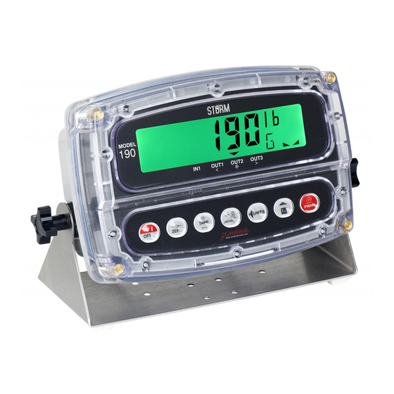
- Page 1 Model 190 Indicator Installation, Technical and Operation Manual Includes Models 190DC, 190A, 190-DAC and Options: BP190, 190-RS232, 190-IP, 190-WIFI and 190-USB...
- Page 3 Model 190 Installation, Technical and Operation Introduction Thank you for selecting and purchasing the Cardinal Model 190 Weight Indicator. The Model 190 indicator was built with quality and reliability and incorporates the latest in digital technology and innovative features for the weighing industry. Configuration and upgrades can easily be performed in the field, while still maintaining the rigid control the most demanding installations require.
- Page 4 Model 190 Installation, Technical and Operation FCC Compliance Statement This equipment generates uses and can radiate radio frequency and if not installed and used in accordance with the instruction manual, may cause interference to radio communications. It has been tested and found to comply with the limits for a Class A computing device pursuant to Subpart J of Part 15 of FCC rules, which are designed to provide reasonable protection against such interference when operated in a commercial environment.
-
Page 5: Table Of Contents
Model 190 Installation, Technical and Operation TABLE OF CONTENTS 1. SPECIFICATIONS ...................... 1 1.1 Standard Features ....................2 1.2 Optional Features ....................2 1.3 European Declaration of Conformity ..............3 2. PRECAUTIONS ......................5 2.1 Static Electricity ....................5 2.2 Batteries ....................... 5 3. - Page 6 Model 190 Installation, Technical and Operation 4.6 Calibration ......................35 4.6.1 Dual-Point with Zero (First Zero) Calibration ..........37 4.6.2 Dual-Point without Zero (False Zero) Calibration ........39 4.6.3 Single-Point for Span Only (Last Zero) Calibration ........41 4.6.4 Single-Point for Zero Only (Only Zero) Calibration ........43 4.6.5 Multi-Point Calibration................
- Page 7 Model 190 Installation, Technical and Operation 8. OPERATION ......................91 8.1 Ticket Format Selection ..................91 8.2 Preset Weight Comparators ................93 8.3 Hold Function ..................... 95 8.4 Count Function ....................97 8.5 Time and Date Functions ................... 99 8.6 Peak Hold Function ..................101 8.7 Checkweigher ....................
- Page 8 Model 190 Installation, Technical and Operation 13. APPENDIX A – BP190 Optional Battery Pack ........... 135 13.1 BP190 Contents: .................... 135 13.2 BP190 Specifications: ..................135 13.3 Installing the BP190 ..................136 14. APPENDIX B – Model 190A ................139 14.1 Traffic Control ....................
- Page 9 Model 190 Installation, Technical and Operation 18. APPENDIX F – 190-DAC Option ................. 169 18.1 Specifications ....................169 18.2 Onboard Status/Diagnostic LED’s ..............170 18.3 Setup ......................171 18.4 DAC Wiring ....................173 19. APPENDIX G – 190-USB Option ................. 175 19.1 Features ......................
-
Page 11: Specifications
Model 190 Installation, Technical and Operation 1. SPECIFICATIONS Power Requirements: 100 to 240 VAC (50/60 Hz) at 0.4A Max. Enclosure Type: Thermoplastic IP69K wall or desk-mount 9.4” W x 6.4” H x 3.7" D Enclosure Size: (239mm W x 163mm H x 93mm D) Operating Environment: Temperature: 14 to 104 ºF (-10 to +40 ºC) Humidity: 90% non-condensing... -
Page 12: Standard Features
Model 190 Installation, Technical and Operation 1.1 Standard Features Push button tare function Gross, tare, net conversion Selectable key lockout Hi-Resolution mode ® 1 StableSENSE adjustable digital filtering Gross and Net accumulators Single serial port Remote input line for Zero, Tare, Gross and Print (1000 feet maximum) Programmable print format using Visual Print or nControl (1 Visual Ticket available) -
Page 13: European Declaration Of Conformity
YY = last two digits of year ZZZ = sequential number The undersigned hereby declares, on behalf of Cardinal Scale Manufacturing Company of Webb City, Missouri, that the above- referenced product, to which this declaration relates, is in conformity with... - Page 14 Model 190 Installation, Technical and Operation 8400-M022-O1 Rev J Page 4...
-
Page 15: Precautions
Model 190 Installation, Technical and Operation 2. PRECAUTIONS 2.1 Static Electricity CAUTION! This device contains static sensitive circuit cards and components. Improper handling of these devices or printed circuit cards can result in damage to or destruction of the component or card. Such actual and/or consequential damage IS NOT covered under warranty and is the responsibility of the device owner. - Page 16 Model 190 Installation, Technical and Operation 8400-M022-O1 Rev J Page 6...
-
Page 17: Installation
Model 190 Installation, Technical and Operation 3. INSTALLATION 3.1 Site Preparation Requirements The Cardinal Model 190 indicator is a precision weight-measuring instrument. As with any precision instrument, it requires an acceptable environment to operate at peak performance and reliability. This section is provided to assist you in obtaining such an environment. -
Page 18: Electrical Power
Model 190 Installation, Technical and Operation Insure that the indicator has good, clean AC power and is properly grounded. In areas subject to lightning strikes, additional protection to minimize lightning damage, such as surge suppressors, should be installed. 3.1.2 Electrical Power The 190 has been designed to operate from 100 to 240 VAC @ 0.4A Max. -
Page 19: Electrical Noise Interference
Model 190 Installation, Technical and Operation 3.1.3 Electrical Noise Interference To prevent electrical noise interference, make certain all other wall outlets for use with air conditioning and heating equipment, lighting or other equipment with heavily inductive loads, such as welders, motors and solenoids are on circuits separate from the indicator. -
Page 20: Mounting
Model 190 Installation, Technical and Operation 3.2 Mounting Before beginning installation of your Model 190 Indicator, make certain that it has been received in good condition. Carefully remove it from the shipping carton and inspect it for any evidence of damage (such as exterior dents or scratches) that may have taken place during shipment. -
Page 21: Load Cell Connections
Model 190 Installation, Technical and Operation 3.3 Load Cell Connections CAUTION! Disconnect any external load cell power supply before connecting load cells to the indicator. Failure to do so will result in permanent damage to the indicator. Scale Figure No. 2 AC Power (Serial, Isolated 100-240 VAC... - Page 22 Model 190 Installation, Technical and Operation 3.3.6. Remove the 7-connector terminal block connector from P5 on the 190 mainboard. Grasp the terminal block connector and lift straight up away from the board. 3.3.7. Referring to the table below and the labels on the circuit board for terminal connections, connect each wire to the terminal block.
-
Page 23: Load Cell Connections With Over 30 Feet Of Cable
Model 190 Installation, Technical and Operation 3.4 Load Cell Connections with Over 30 Feet of Cable For installations with over 30 feet of cable between the indicator and the load cells, sense wires should be used. The sense wires must be connected between the +SENS, -SENS terminals on the indicator and the +EXCITATION, -EXCITATION wires of the load cells or the +SENS, - SENS terminals of the load cell trim board or the section seal trim board. -
Page 24: Serial And I/O Cable Installation
Model 190 Installation, Technical and Operation 3.6 Serial and I/O Cable Installation 3.6.1. Loosen the 4 Captive screws securing the rear housing to the front housing assembly and then loosen a gland connector for the serial cable. Refer to Figure No. 2 for an illustration of the connector layout. -
Page 25: P3 I/O Interconnections
Model 190 Installation, Technical and Operation 3.7 P3 I/O Interconnections Figure No. 7 3.8 P2 Power Connections P2 Board Label Function Ground CHGND Chassis Ground +BAT + (Plus) Battery -BAT - (Minus) Battery Figure No. 8 8400-M022-O1 Rev J Page 15... -
Page 26: Re-Installing The Front Panel
Model 190 Installation, Technical and Operation 3.9 Re-Installing the Front Panel 3.9.1. After all terminations have been made, remove the excess cable from the indicator enclosure and securely tighten each of the cable gland connectors. 3.9.2. Use a wrench to insure the gland connectors are tight (to maintain a water-tight seal) but do not over-tighten them. -
Page 27: Indicator Setup
Model 190 Installation, Technical and Operation 4. INDICATOR SETUP 4.1 Calibration Inhibit Jumper Your Model 190 indicator has been thoroughly tested and calibrated before being shipped to you. If you received the indicator attached to a scale, calibration is not necessary. If the indicator is being connected to a scale for the first time or recalibration is necessary for other reasons, proceed as indicated. - Page 28 Model 190 Installation, Technical and Operation IMPORTANT! The following setup parameters CAN NOT be changed with the calibration inhibit jumper (J4) installed: Domestic or International Legal For Trade Unit1 Weighing Units 1 (Primary Units) Interval Setting Decimal Point Precision Capacity Unit2 Weighing Units 2 (Secondary Units) Zero Tracking Range 4% Zero Limit...
-
Page 29: Calibration Data Entry
Model 190 Installation, Technical and Operation 4.2 Calibration Data Entry The Model 190 uses a capacitive touch keypad that requires a “finger touch” to function. The keypad will not operate with other items such as pen, pencil or tools. Figure No. 10 During the indicator setup and calibration process it will be necessary to enter operational parameters via the 190 keypad. - Page 30 Model 190 Installation, Technical and Operation 8400-M022-O1 Rev J Page 20...
-
Page 31: Accessing Setup
Model 190 Installation, Technical and Operation 4.3 Accessing Setup 4.3.1. With the 190 ON, press the Fn/ and UNITS/ key simultaneously 4.3.2. Hold both keys until the display changes to SetUP. 4.3.3. Release the keys to begin setup. 4.3.4. Press the UNITS/ key to step to the beginning point of each setup section. - Page 32 Model 190 Installation, Technical and Operation 8400-M022-O1 Rev J Page 22...
-
Page 33: Settings
Model 190 Installation, Technical and Operation 4.4 Settings IMPORTANT! Calibration and configuration parameters are not stored in the non-volatile memory until setup is left. If power is lost while in setup mode, any changes made will be lost and the indicator will revert to the previous configuration. - Page 34 Model 190 Installation, Technical and Operation Unit1= (Weighing Unit 1) Press the TARE key to show the current setting. If the setting displayed is acceptable, press the TARE key again to save it. Otherwise, use the Fn/ key to toggle to a new setting and then press the TARE ...
- Page 35 Model 190 Installation, Technical and Operation Unit2= (Weighing Unit 2) Press the TARE key to show the current setting. If the setting displayed is acceptable, press the TARE key again to save it. Otherwise, use the Fn/ key to toggle to a new setting and then press the TARE ...
- Page 36 Model 190 Installation, Technical and Operation PUO= (Power-Up Zero Feature) Press the TARE key to show the current setting. If the setting displayed is acceptable, press the TARE key again to save it. Otherwise, use the Fn/ key to toggle to a new setting and then press the TARE ...
- Page 37 Model 190 Installation, Technical and Operation d in= X,Y (Digital Input) Press the TARE key to show the current setting. If the setting displayed is acceptable, press the TARE key again to save it. Otherwise, use the Fn/ key to select the X, Y settings for the Digital Input, and then press the TARE ...
- Page 38 Model 190 Installation, Technical and Operation d oUt= X,Y (Digital Output) Press the TARE key to show the current setting. If the setting displayed is acceptable, press the TARE key again to save it. Otherwise, use the Fn/ key to select the X, Y settings for the Digital Output, and then press the TARE ...
- Page 39 Model 190 Installation, Technical and Operation SLEEP= (Sleep Mode Feature) The Sleep Mode feature conserves battery power when the indicator remains unused for a selected period of time. With the feature enabled, the display will be blank. Press the TARE key to show the current status of this feature. If a number other than 0 is shown, this feature is selected and the number shown corresponds to the number of minutes of a stable zero weight reading before the indicator enters the sleep mode.
- Page 40 Model 190 Installation, Technical and Operation batt= (Battery Installed) Press the TARE key to show the current setting. If the setting displayed is acceptable, press the TARE key again to save it. Otherwise, use the Fn/ key to toggle to a new setting and then press the TARE ...
-
Page 41: Analog To Digital Filtering
Model 190 Installation, Technical and Operation 4.5 Analog to Digital Filtering With A-d displayed, press the TARE key. The display will change to dFLt=. Proceed to the dFLt= parameter. A-d? With A-d? displayed, press the TARE key. The display will change to no. - Page 42 Model 190 Installation, Technical and Operation F= (Filter Level) The filter level is a number from 1 to 99 that corresponds to the level of filtering with 1 being the least and 99 being the greatest. Press the TARE key to show the current setting. To accept the setting displayed, press the TARE ...
-
Page 43: Filter Setting Recommendations
Model 190 Installation, Technical and Operation 4.5.1 Filter Setting Recommendations Non Critical Sample Rate If the sample rate is not critical, as in static weighing, set: dFLt= 0 (F=2, b=1), dFLt= 1 (F=6, b=12, Sr= 2), or dFLt= 2 (F=20, b=12, Sr= 1). - Page 44 Model 190 Installation, Technical and Operation 8400-M022-O1 Rev J Page 34...
-
Page 45: Calibration
Model 190 Installation, Technical and Operation 4.6 Calibration The 190 indicator has six modes that can be used to perform calibration. Four of the modes require a test load or test weights, one requires the scale to be empty (and at zero) and the last uses the calibration “C” numbers from a previous calibration. - Page 46 Model 190 Installation, Technical and Operation 8400-M022-O1 Rev J Page 36...
-
Page 47: Dual-Point With Zero (First Zero) Calibration
Model 190 Installation, Technical and Operation 4.6.1 Dual-Point with Zero (First Zero) Calibration This is a standard calibration method requiring one weight, an empty scale and has one conversion factor. This method uses two calibration points (CAL1= and CAL2=) to establish a zero (no load) calibration value and to span the indicator. - Page 48 Model 190 Installation, Technical and Operation CAL3= – Last Calibration Weight The display will show CAL3=. This weight is not used. Press the UNITS/ key to skip CAL3= and advance to SetgC? prompt. 8400-M022-O1 Rev J Page 38...
-
Page 49: Dual-Point Without Zero (False Zero) Calibration
Model 190 Installation, Technical and Operation 4.6.2 Dual-Point without Zero (False Zero) Calibration This calibration method requires one test weight and establishes a new conversion factor only. It is used to establish a false (temporary zero) zero without affecting the zero calibration value stored during the last calibration. - Page 50 Model 190 Installation, Technical and Operation 8400-M022-O1 Rev J Page 40...
-
Page 51: Single-Point For Span Only (Last Zero) Calibration
Model 190 Installation, Technical and Operation 4.6.3 Single-Point for Span Only (Last Zero) Calibration This calibration method requires one test weight and establishes a new conversion factor (span) without affecting the zero calibration value stored during the last calibration. This minimizes placing and removing test weights and is especially useful when checking high capacity scales. - Page 52 Model 190 Installation, Technical and Operation 8400-M022-O1 Rev J Page 42...
-
Page 53: Single-Point For Zero Only (Only Zero) Calibration
Model 190 Installation, Technical and Operation 4.6.4 Single-Point for Zero Only (Only Zero) Calibration This calibration method requires no test weight, an empty scale and establishes a new zero without affecting the conversion factor (span). This is useful to regain the full range of zero limit when the dead load of the scale has changed. - Page 54 Model 190 Installation, Technical and Operation 8400-M022-O1 Rev J Page 44...
-
Page 55: Multi-Point Calibration
Model 190 Installation, Technical and Operation 4.6.5 Multi-Point Calibration This method requires up to four weights, an empty scale and has up to four conversion factors. This method uses up to five calibration points (CAL1=, CAL2=, CAL3=, CAL4=, and CAL5=). The five points correspond to zero weight, up to three midpoint weights, and the test load or test weight and can be applied in any order. - Page 56 Model 190 Installation, Technical and Operation CAL3= – Third Calibration Weight The display will show CAL3=. This is the second of two calibration weights. This weight could be ZERO (NO LOAD) or the TEST WEIGHTS (TEST LOAD). Press the TARE key to view the current setting. If the second calibration weight is to be ZERO (NO LOAD), press the TARE ...
- Page 57 Model 190 Installation, Technical and Operation CAL5= – Last Calibration Weight The display will show CAL5=. This is the fifth of the calibration weights. This weight could be ZERO (NO LOAD) or the TEST WEIGHTS (TEST LOAD). If the fifth calibration weight is not going to be used, press the UNITS/...
- Page 58 Model 190 Installation, Technical and Operation 8400-M022-O1 Rev J Page 48...
-
Page 59: Calibration "C" Numbers
Model 190 Installation, Technical and Operation 4.6.6 Calibration “C” Numbers IMPORTANT! If any components have been changed that affect calibration and/or your scale is used in a commercial application and must be "Legal for Trade" you cannot use the “C” numbers to re-calibrate. - Page 60 Model 190 Installation, Technical and Operation 8400-M022-O1 Rev J Page 50...
-
Page 61: Set Gravity Constant
Model 190 Installation, Technical and Operation 4.7 Set Gravity Constant The Cardinal 190 Weight Indicator is equipped with an acceleration of gravity function which means that it can be calibrated in one location and then adjusted to match the acceleration of gravity at the location where it will used. - Page 62 Model 190 Installation, Technical and Operation 8400-M022-O1 Rev J Page 52...
-
Page 63: Serial Input/Output
Model 190 Installation, Technical and Operation 4.8 Serial Input/Output With sio displayed, press the TARE key. The display will change to baud=. Proceed to the baud= parameter. Sio? With sio? displayed, press the TARE key. The display will change to no. - Page 64 TARE key to save it. Allowable settings are: 0 = Continuous Output uses SMA format 1 = Continuous Output uses Cardinal Scoreboard format 4.8.1 SMA Continuous Output Format If SMA is selected, data will be transmitted in the following format: <lf><s><r><n><m><f><xxxxxx.xxx><uuu><cr>...
- Page 65 Model 190 Installation, Technical and Operation 4.8.2 Cardinal Scoreboard Continuous Output Format If Cardinal Scoreboard is selected, the data will be transmitted in the following format: <s><xxxxxx><d><uu><m><cc><cr> Where: Sign "-" = negative, " " (blank) = positive xxxxxx = Weight...
- Page 66 Model 190 Installation, Technical and Operation 4.8.4 Operation Commands A connection to the 190 serial port RXD serial input can be used to send commands to the 190 indicator. A description of the available commands are describe in section 9.11 ASCII Commands. 8400-M022-O1 Rev J Page 56...
-
Page 67: Print Tab Settings
Model 190 Installation, Technical and Operation 4.9 Print Tab Settings Print With Print displayed, press the TARE key. The display will change to port=. Proceed to the port= parameter. Print? With Print? displayed, press the TARE key. The display will change to no. - Page 68 Model 190 Installation, Technical and Operation HoUr= (Time Print Location) Press the TARE key to show the current setting for the Time Print Location. If the setting displayed is acceptable, press the TARE key again to save it. Otherwise, use the Fn/ and UNITS/...
- Page 69 Model 190 Installation, Technical and Operation g ACC= (Gross Weight Accumulator Print Location) Press the TARE key to show the current setting for the Gross Weight Accumulator Print Location. If the setting displayed is acceptable, press the TARE key again to save it. Otherwise, use the Fn/ and UNITS/ keys to enter a new location and then press the TARE ...
- Page 70 Model 190 Installation, Technical and Operation EoP= (End-Of-Print Line Feeds) At the end of a data transmission to a printer, the indicator can transmit a pre-selected number of line feed commands to space the paper in the printer to the desired position for withdrawal or for the next print.
-
Page 71: Fine Span Adjustment
Model 190 Installation, Technical and Operation 4.10 Fine Span Adjustment IMPORTANT! The FSPAn (FSPAn?) mode requires a load of 10% of Capacity on the scale before adjustments can be made. F span Fine Span Adjustment (from SETUP Prompt) If Fine Span Adjustment is desired, with the SETUP prompt displayed, press the UNITS/... - Page 72 Model 190 Installation, Technical and Operation 8400-M022-O1 Rev J Page 62...
-
Page 73: Display High Resolution Weight
Model 190 Installation, Technical and Operation 4.11 Display High Resolution Weight IMPORTANT! The Hires (Hires?) mode requires a load of 10% of Capacity on the scale. Hi res High Resolution Weight (from SETUP Prompt) If displaying High Resolution Weight is desired, with the SETUP prompt displayed, press UNITS/... - Page 74 Model 190 Installation, Technical and Operation 8400-M022-O1 Rev J Page 64...
-
Page 75: Key Lockout Feature
Model 190 Installation, Technical and Operation 4.12 Key Lockout Feature The Key Lockout Feature allows keys on the indicator to be disabled for use by the operator “during normal operation”. During normal operation, when the operator presses a locked key, the display will show LoCd for about a 1/2 second and the key will be ignored. - Page 76 Model 190 Installation, Technical and Operation net= (NET/GROSS Key) Press the TARE key to show the current setting. If the setting displayed is acceptable, press the TARE key again to save it. Otherwise, use the Fn/ key to toggle to a new setting and then press the TARE ...
- Page 77 Model 190 Installation, Technical and Operation on= (ON/OFF Key) Press the TARE key to show the current setting. If the setting displayed is acceptable, press the TARE key again to save it. Otherwise, use the Fn/ key to toggle to a new setting and then press the TARE ...
- Page 78 Model 190 Installation, Technical and Operation 8400-M022-O1 Rev J Page 68...
-
Page 79: Options Setup
Model 190 Installation, Technical and Operation 4.13 Options Setup option With opt displayed, press the TARE key. The display will change to show opt=. Proceed to the opt= parameter. opt? With opt? displayed, press the TARE key. The display will change to no. - Page 80 TARE key to save it. Allowable settings are: 0 = Continuous Output uses SMA format 1 = Continuous Output uses Cardinal Scoreboard format NOTE: Refer to the CONT1= Continuous Output on Serial Interface, tYPE= parameter for description of output formats.
-
Page 81: Function Setup
Model 190 Installation, Technical and Operation 4.14 Function Setup fUnC With FUnC displayed, press the TARE key. The display will change to show Hold=. Proceed to the Hold = parameter. FUnC? With FUnC? displayed, press the TARE key. The display will change to no. - Page 82 Model 190 Installation, Technical and Operation Ti-da= (Time and Date) Press the TARE key to show the current setting. If the setting displayed is acceptable, press the TARE key again to save it. Otherwise, use the Fn/ key to toggle to a new setting and then press the TARE ...
- Page 83 Model 190 Installation, Technical and Operation aCCU= (Weight Accumulation Function) Press the TARE key to show the current setting. If the setting displayed is acceptable, press the TARE key again to save it. Otherwise, use the Fn/ key to toggle to a new setting and then press the TARE ...
- Page 84 Model 190 Installation, Technical and Operation 8400-M022-O1 Rev J Page 74...
-
Page 85: Display Backlight Color Setup
Model 190 Installation, Technical and Operation 4.15 Display Backlight Color Setup CoLorS With Colors displayed, press the TARE key. The display will change to show dflt=. Proceed to the dflt= parameter. Color? With Color? displayed, press the TARE key. The display will change to no. - Page 86 Model 190 Installation, Technical and Operation aCCpt= (Checkweigher “Accept” Backlight Color) Press the TARE key to show the current setting. If the setting displayed is acceptable, press the TARE key again to save it. Otherwise, use the Fn/ key to toggle to a new setting and then press the TARE ...
-
Page 87: Keypad
Model 190 Installation, Technical and Operation 5. KEYPAD 5.1 Standard Key Functions The Model 190 is equipped with a 7-key Capacitive Touch keypad. The keypad is used to enter commands and data into the indicator. This section describes each key along with its normal function. It is helpful to refer to the actual indicator while reading this section. - Page 88 Model 190 Installation, Technical and Operation Description ON/OFF: The ON/OFF key is used to turn the indicator on and off. Press the ON/OFF key when the indicator is off to turn the indicator ON. The 190 will perform a display test (turn on all segments) and then show the model number and software version.
- Page 89 Model 190 Installation, Technical and Operation Description TARE (Enter): The TARE key is used during normal operation to store the current Gross weight as the new Tare weight. The display will change to the Net weight and the Net annunciator will turn on. ...
- Page 90 Model 190 Installation, Technical and Operation Description Fn/ (Up Arrow): The Fn/ key is used for several functions. During indicator setup, when a setup parameter (not a parameter value or setting) is displayed, pressing the Fn/ key will "backup" to the previous parameter prompt. ...
-
Page 91: Fn/ Key Functions
Model 190 Installation, Technical and Operation 5.2 Fn/ Key Functions The Fn/ key is used to select several additional functions that may have been enabled during the setup and calibration of the indicator. Those functions include: Hold, Count, Time and Date, Peak Hold, Checkweigher, Live Weight, Weight Accumulation and Backlight Color. - Page 92 Model 190 Installation, Technical and Operation 8400-M022-O1 Rev J Page 82...
-
Page 93: Fn/ Key Combination Features
Model 190 Installation, Technical and Operation 5.3 Fn/ Key Combination Features The Fn/ key is also used in combination with the other keys on the keypad to access additional indicator features. Those features and their associated key combinations are as follows: Fn/, ZERO KEY This combination will enter the Review mode of Setup and Calibration. - Page 94 Model 190 Installation, Technical and Operation 8400-M022-O1 Rev J Page 84...
-
Page 95: Annunicators
Model 190 Installation, Technical and Operation 6. ANNUNICATORS 6.1 Annunicators The Model 190 is equipped with annunciators that are turned on to indicate that the display is in the mode corresponding to the annunciator label or that the status indicated by the label is active. This section describes each annunciator. - Page 96 Model 190 Installation, Technical and Operation This annunciator is located to kilograms the right of the weight display and is used to indicate that the displayed unit of weight measurement is kilograms. This annunciator is located to grams the right of the weight display and is used to indicate that the displayed unit of weight measurement is grams.
- Page 97 Model 190 Installation, Technical and Operation This annunciator is used to signal ACCEPT that the displayed weight is within OUT2 the acceptable weight limits for the Checkweigher feature. That is, the weight is equal to or greater than the minimum acceptable weight and equal to or less than the maximum acceptable weight.
-
Page 98: Battery Status
Model 190 Installation, Technical and Operation 6.2 Battery Status The battery status indicator will be displayed when a battery pack is installed. The number of bars indicates the level of charge. Number of Bars Level of Charge 100% Note that as the battery approaches full discharge, the outline of the battery will start to flash. -
Page 99: Indicator Setup Review
(Select YES or NO) baUd= Select Serial Port Baud Rate prty= Select Serial Port Parity Cont1= Enable or Disable Continuous Output to the Serial Port type= If Cont1=YES (Select Continuous Output Format, SMA or Cardinal Scoreboard) 8400-M022-O1 Rev J Page 89... - Page 100 Select Option Card Parity when Opt= 0 or 1 Cont2= Enable or Disable Continuous Output to the Option Port type= If Opt=1 and Cont2=YES (Select Continuous Output Format, SMA or Cardinal Scoreboard) baUd= Select Field Bus Option Baud Rate when Opt= 2...
-
Page 101: Operation
Model 190 Installation, Technical and Operation 8. OPERATION 8.1 Ticket Format Selection The 190 includes support for visual tickets. Visual tickets are designed by the PC based programs Visual Print or nControl and then downloaded to the indicator. The 190 allows one programmable format in addition to the standard print tab settings format. - Page 102 Model 190 Installation, Technical and Operation 8400-M022-O1 Rev J Page 92...
-
Page 103: Preset Weight Comparators
Model 190 Installation, Technical and Operation 8.2 Preset Weight Comparators The Model 190 indicator has three (3) outputs, which can be configured during setup to perform as Preset Weight Comparators “PWC”. The output state of each PWC (before reaching the preset weight) is defined in section 4.4 SETUP, the d out= (Digital Output) parameter. - Page 104 Model 190 Installation, Technical and Operation 8.2.2 Preset Weight Comparators Operation The preset weight comparators are used to control peripheral devices used in some form of process control. The number of comparators used depends upon system needs. For example, in a simple filling operation, a single comparator may be used to open or close a gate which dumps material on the scale.
-
Page 105: Hold Function
Model 190 Installation, Technical and Operation 8.3 Hold Function With the Hold function enabled during setup of the indicator, the function must be activated before it can be used. Refer to section 4.14 Function Setup, the FUnC (FUnC?) parameter to enable the Fn/... - Page 106 Model 190 Installation, Technical and Operation 8400-M022-O1 Rev J Page 96...
-
Page 107: Count Function
Model 190 Installation, Technical and Operation 8.4 Count Function With the Count function enabled during setup of the indicator, the function must be activated before it can be used. Refer to section 4.14 Function Setup, the FUnC (FUnC?) parameter to enable the Fn/... - Page 108 Model 190 Installation, Technical and Operation Additional pieces may be added and the display will show the total number of pieces. Press the NET/GROSS key to return to the weight display. After the average piece weight has been set, pressing the Fn/...
-
Page 109: Time And Date Functions
Model 190 Installation, Technical and Operation 8.5 Time and Date Functions With the Time and Date function enabled during setup of the indicator, the function must be activated before it can be used. Refer to section 4.14 Function Setup, the FUnC (FUnC?) parameter to enable the Fn/... - Page 110 Model 190 Installation, Technical and Operation 8400-M022-O1 Rev J Page 100...
-
Page 111: Peak Hold Function
Model 190 Installation, Technical and Operation 8.6 Peak Hold Function With the Peak Hold function enabled during setup of the indicator, the function must be activated before it can be used. Refer to section 4.14 Function Setup, the FUnC (FUnC?) parameter to enable the Fn/... - Page 112 Model 190 Installation, Technical and Operation 8400-M022-O1 Rev J Page 102...
-
Page 113: Checkweigher
Model 190 Installation, Technical and Operation 8.7 Checkweigher The Model 190 indicator has logic level outputs that can be used to control peripheral devices used to signal when the weight is within preset limits. The output state of the Checkweigher (before reaching the preset weight) is defined in section 4.4 SETUP, the d out= (Digital Output) parameter. - Page 114 Model 190 Installation, Technical and Operation The display will change to show the Hi 1= prompt. Press the TARE key again. The display will show the current value for the maximum acceptable weight for ID 1. If the setting displayed is acceptable, press the TARE key to save it.
- Page 115 Model 190 Installation, Technical and Operation 8.7.2 Target Weight Selection From the weight display, briefly press and then release the Fn/▲ key. The display will show the prompt id=. Press the TARE key. The display will show the ID of the currently selected target weight. If the setting displayed is acceptable, press the TARE key to save it.
- Page 116 Model 190 Installation, Technical and Operation 8400-M022-O1 Rev J Page 106...
-
Page 117: Live Weight Function
Model 190 Installation, Technical and Operation 8.8 Live Weight Function With the Live Weight function enabled during setup of the indicator, the function must be activated before it can be used. Refer to section 4.14 Function Setup, the FUnC (FUnC?) parameter to enable the Fn/... - Page 118 Model 190 Installation, Technical and Operation 8400-M022-O1 Rev J Page 108...
-
Page 119: Accumulated Weight Function
Model 190 Installation, Technical and Operation 8.9 Accumulated Weight Function When the accumulated weight function has been enabled during setup of the indicator, the function must be activated before it can be used. Refer to section 4.14 Function Setup, the FUnC (FUnC?) parameter to enable the Fn/... - Page 120 Model 190 Installation, Technical and Operation The display will alternate between showing the Gross accumulator weight and the Gross accumulator count. Press the TARE key and the Net accumulator weight will be displayed, indicated by the alternating n and A. After a brief interval, the display will show the number of Net weight items accumulated, indicated by the alternating N and The display will alternate between showing the Net...
-
Page 121: Touch Key Lock Out Function
Model 190 Installation, Technical and Operation 8.10 Touch Key Lock Out Function The 190 firmware provides a means for locking out the capacitive touch keys. When the keys are locked out, any activation of the keys, whether intentional or accidental, will be ignored. NOTE: This function is available in firmware version 1.0.13 or newer. - Page 122 Model 190 Installation, Technical and Operation 8400-M022-O1 Rev J Page 112...
-
Page 123: Ascii Commands
“Weight On Demand” output format. Request Displayed Weight Command (Scoreboard Format) The wireless device sends: <ENQ> (hex 05) The 190 will respond with weight in Cardinal Scoreboard format: <S><XXXXXX><d>_<UU>_<m>_<cc>_<CR> where: <S> sign “-”... - Page 124 Model 190 Installation, Technical and Operation Request Displayed Weight Command (SMA Format) The wireless device sends: <LF>W<CR> The 190 will respond with displayed weight in SMA format: <LF><s><r><n><m><f><xxxxxxx.xxx><uuu><CR> where: <LF> line feed (hex 0A) <s> scale status Z = center of zero O = over capacity U = under capacity E = zero error...
- Page 125 Model 190 Installation, Technical and Operation Request Scale To Zero Command The wireless device sends: <LF>Z<CR> The 190 will attempt to zero the scale and respond with weight in SMA format. Scale status will indicate if the attempt to zero was unsuccessful. Request Scale To Tare Command The wireless device sends: <LF>T<CR>...
- Page 126 About Scale Scroll Command The wireless device sends: <LF>B<CR> The 190 will respond with the following (NOTE: The command must be repeated for each response): <LF>MFG:Cardinal Scale Mfg. Co.<CR> <LF>MOD:190<CR> <LF>REV:n.n.nn/1.1<CR> <LF>END:<CR> NOTE: n.n.nn will be the version number for the 190 firmware.
- Page 127 Model 190 Installation, Technical and Operation Scale Information Scroll Command The wireless device sends: <LF>N<CR> The 190 will respond with the following (NOTE: the command must be repeated for each response): <LF>TYP:S<CR> <LF>CAP:uuu:ccc:n:d<CR> <LF>CMD:TMCIN<CR> <LF>END:<CR> The CAP response will be repeated once for each unit of measure. uuu is the units of measure.
- Page 128 Model 190 Installation, Technical and Operation Abort Command The wireless device sends: <ESC> (hex 1B) The 190 will clear any pending commands. The 190 will not send a response to this command. Unrecognized Command Response If the 190 receives a command it does not recognize it will respond with <LF>?<CR>...
-
Page 129: Error Messages
9. ERROR MESSAGES 9.1 Before You Call Service The Cardinal 190 Weight Indicator has been designed to provide you with years of trouble-free operation. However, should you experience a problem, please refer to the troubleshooting guide below before you call for service. - Page 130 Model 190 Installation, Technical and Operation The printer prints The print tab setting or visual ticket format but does not use must be selected prior to beginning the the Print Tab weighing operation or just prior to printing the Settings or prints ticket.
-
Page 131: Error Codes
Model 190 Installation, Technical and Operation 9.2 Error Codes The Cardinal 190 Weight Indicator is equipped with software that indicates when an error in the operation takes place. The following lists the error codes displayed by the 190 along with their meaning. Should you encounter an error code, please refer to this list for the cause. - Page 132 Model 190 Installation, Technical and Operation Error Cause (A.) and Corrective Action (B.) The NET/GROSS key was pressed when there is notArE no stored tare. A. The load on the scale exceeds the capacity of oCAP the scale. B. Remove the excess load. A.
-
Page 133: Event Counters
10. EVENT COUNTERS 10.1 Event Counters The Cardinal Model 190 has been designed with a Category 1 Event Counter type of security seal. The 190 will display two event counters that increment when a change is made to features that are required by NTEP or OIML to be sealed. - Page 134 Model 190 Installation, Technical and Operation Configuration Parameters Domestic or International Legal For Trade Unit1 Weighing Units 1 (Primary Units) Interval Setting Decimal Point Precision Capacity Unit2 Weighing Units 2 (Secondary Units) Zero Tracking Range 4% Zero Limit Power Up Zero dFLt Digital Filter Number Filter Level Amount...
-
Page 135: Test Mode/ Diagnostics
Model 190 Installation, Technical and Operation 11. TEST MODE/ DIAGNOSTICS 11.1 Test Mode/Diagnostics Features The Cardinal Model 190 Weight Indicator has a comprehensive diagnostics feature that can allow it to self-diagnose a problem. After displaying the model number, software revision and performing a display test, the indicator will enter the diagnostics mode. -
Page 136: Parts Identification
Model 190 Installation, Technical and Operation 12. PARTS IDENTIFICATION 12.1 Front Sub-Assembly 8400-M022-O1 Rev J Page 126... - Page 137 Model 190 Installation, Technical and Operation 12.1 Front Sub-Assembly, Cont. ITEM NO. QTY. PART NUMBER DESCRIPTION 593GR986 SERIAL TAG ASSY 6021-1286 SCW PAN-HEAD PLASTIC THD. ROLLING, #4x1/4, PHIL. DR. Z/P 6021-1287 SCW PAN-HEAD PLASTIC THD. ROLLING, #4x1/2, PHIL. DR. Z/P 8400-B014-08 CONNECTOR GASKET, 190 8400-C013-08...
-
Page 138: Rear Sub-Assembly
Model 190 Installation, Technical and Operation 12.2 Rear Sub-Assembly ITEM NO. QTY. PART NUMBER DESCRIPTION 6021-1286 SCW PAN-HEAD PLASTIC THD. ROLLING, #4x1/4, PHIL. DR. Z/P 6024-0037 WASHER LOCK HELICAL SP #10 REG SS 6610-2248 CONN GLAND .187-.312 GRIP .599 MTG BLK 6980-0250 190EU POWER CORD H05W-F3G 1mm, 10A/250V, BLACK... -
Page 139: Power Supply Sub-Assy
Model 190 Installation, Technical and Operation 12.3 190 Power Supply Sub-Assy. ITEM NO. QTY. PART NUMBER DESCRIPTION 6021-0423 SCW PAN-HEAD.. MACHINE-SCW 04-40X.250 6021-2018 SCW PAN-HEAD.. MACHINE-SCW 04-40X.875 CABLE CLIP, 1” X 1” GREY 6610-5007 6680-0026 WASHER LOCK INT TOOTH #4 TYPE A Z-PL 6680-0138 SPACER #6 X .187 NYLON 6680-1107... -
Page 140: Ac Wiring Detail
Model 190 Installation, Technical and Operation 12.4 AC Wiring Detail 12.5 P2 Wiring Detail 8400-M022-O1 Rev J Page 130... -
Page 141: 190Dc Rear Sub-Assembly
Model 190 Installation, Technical and Operation 12.6 190DC Rear Sub-Assembly ITEM NO. QTY. PART NUMBER DESCRIPTION 6021-1286 SCW PAN-HEAD PLASTIC THD. ROLLING, #4x1/4, PHIL. DR. Z/P 6024-0037 WASHER LOCK HELICAL SP #10 REG SS 6610-2248 CONN GLAND .187-.312 GRIP .599 MTG BLK 8200-B567-08 LABEL: 825-DCPOWER 8400-B020-08... -
Page 142: 190Dc Power Supply Sub-Assy
Model 190 Installation, Technical and Operation 12.7 190DC Power Supply Sub-Assy. ITEM NO. QTY. PART NUMBER DESCRIPTION 6021-0420 SCW ROUND-HEAD MACHINE-SCW 04-40X.375 6021-2018 SCW PAN-HEAD.. MACHINE-SCW 04-40X.875 CABLE CLIP, 1” X 1” GREY 6610-5007 6680-0026 WASHER LOCK INT TOOTH #4 TYPE A Z-PL 6680-0138 SPACER #6 X .187 NYLON 6680-1107... -
Page 143: 190Dc Wiring Detail
Model 190 Installation, Technical and Operation 12.8 190DC Wiring Detail 12.9 190DC POWER OPTIONS (not shown) (Must select from power options listed below) PS190 AC ADAPTER FOR 190DC 190DC6 190DC PWR CONN. W/6 FT CABLE & BATTERY TERM. EYELETS 190DC12 190DC PWR CONN. - Page 144 Model 190 Installation, Technical and Operation 8400-M022-O1 Rev J Page 134...
-
Page 145: Appendix A - Bp190 Optional Battery Pack
Model 190 Installation, Technical and Operation 13. APPENDIX A – BP190 Optional Battery Pack 13.1 BP190 Contents: DESCRIPTION PART NUMBER CABLE TIE LARGE 8" SST2SM 6610-5033 BATTERY PACK LI-ION 7.2V, 2600 mAH 6” 6800-1072 LEADS 13.2 BP190 Specifications: DISCHARGE CURRENTS Backlight # of Cells Current ~ Continuous Operation... -
Page 146: Installing The Bp190
Model 190 Installation, Technical and Operation 13.3 Installing the BP190 1. Loosen the 4 Captive screws securing the rear housing to the front housing assembly. 2. Remove 5-connector terminal block from P2 on 190 main board. 3. Referring to labels on circuit board for terminal connections, connect each wire to terminal block. - Page 147 Model 190 Installation, Technical and Operation Slots in Power Supply Cover Cable Ties Battery Pack Cable Ties Connected Together See Step 5 Note and Images Below. WRONG! Do Not Position Cable Ties Connection on CORRECT! Front of Batteries. Position Cable Ties Connection on Top of Batteries.
- Page 148 Model 190 Installation, Technical and Operation 8400-M022-O1 Rev J Page 138...
-
Page 149: Appendix B - Model 190A
14. APPENDIX B – Model 190A Designed for non-legal-for-trade portable axle weighing applications such as with Cardinal’s CWL-40 and 760 series mobile wheel weighers, the Model 190A weight indicator features axle weighing software, traffic control mode to automatically capture accumulative axle weights without... -
Page 150: Axle Weighing Mode
Model 190 Installation, Technical and Operation 14.2 Axle Weighing Mode Setup Axle weighing mode is enabled by setting the d oUt= parameter to 5, setting the aUto= parameter to determine whether the scale will be an automatic axle weigher or will function as a standard axle weigher, setting the printer Port number to 1 or 2 and setting the continuous output Cont on the selected port to NO. - Page 151 Model 190 Installation, Technical and Operation When AUTo=YES, the following additional prompts will be displayed. tHrS= (Threshold Weight) The user can enter a one to six digit number. This value will be the threshold weight or trip point above which the system will consider a truck to be on the scale.
- Page 152 Model 190 Installation, Technical and Operation IMPORTANT! The following prompt, id= (ID Prompt) is displayed after the touch= (Key Touch Sensitivity) parameter ONLY in the Model 190A. id= (ID Prompt) The id= (ID=) parameter enables an ID prompt to be displayed when the PRINT key is pressed and printed a ticket.
-
Page 153: Standard Axle Weighing Operation
Model 190 Installation, Technical and Operation 14.3 Standard Axle Weighing Operation After placing the wheel load weighers on the ground in front of the steering axle, the two weighers are connected together using the interconnection cable assembly. One weigher (makes no difference which) is connected to the indicator using the indicator interface cable. - Page 154 Model 190 Installation, Technical and Operation 13. Have the vehicle driven forward until the next set of wheels are centered on the axle load weighers. 14. Press the PRINT key. 15. Repeat the process for the remaining axles. 16. After the last axle of the group, the total weight of the axles in the group will be printed.
-
Page 155: Auto Axle Weighing Operation
Model 190 Installation, Technical and Operation 14.4 Auto Axle Weighing Operation 1. In the idle state the light will be green and the system will wait for a truck to approach 2. The first axle is driven on the scale and the weight exceeds tHrS, the threshold weight. -
Page 156: Wiring
Interface, tYPE= parameter section 4.8.1 and 4.8.2 for description of output formats 0 and 1. Cardinal SB500 with traffic control Continuous Output Format If Cardinal SB500 with traffic control is selected, the data will be transmitted in the following format: %NDDDDDDDDDT<CR>... -
Page 157: Scoreboard Interconnections
Model 190 Installation, Technical and Operation 14.6 Scoreboard Interconnections Serial Option Card P4 Wiring RS232 Wiring 20mA Current Loop (Passive) 8400-M022-O1 Rev J Page 147... - Page 158 Model 190 Installation, Technical and Operation 8400-M022-O1 Rev J Page 148...
-
Page 159: Appendix C - 190-Rs232 Option
Model 190 Installation, Technical and Operation 15. APPENDIX C – 190-RS232 Option 15.1 Specifications Function: Provide additional serial port for 190 series indicators Temperature Range: 14 to 104 F (-10 to +40 C) Internal Connection: 10-pin DIL External Connection: 7 terminal pluggable connector 15.2 Onboard Status/Diagnostic LED’s... -
Page 160: Setup
Model 190 Installation, Technical and Operation 15.3 Setup Enter SETUP and proceed to the Options Setup. option With option displayed, press the TARE key. The display will change to show opt=. Proceed to the opt= parameter. opt? With opt? displayed, press the TARE key. The display will change to no. - Page 161 0 = Continuous Output uses SMA format 1 = Continuous Output uses Cardinal Scoreboard format 2 = Continuous Output uses Cardinal SB500 with traffic control format NOTE: Refer to the CONT1= Continuous Output on Serial Interface, tYPE= parameter section 4.8.1 and 4.8.2 for description of output formats 0 and 1.
-
Page 162: 190-Rs232 Wiring
Model 190 Installation, Technical and Operation Cardinal SB500 with traffic control Continuous Output Format If Cardinal SB500 with traffic control is selected, the data will be transmitted in the following format: %NDDDDDDDDDT<CR> Where: Panel number for a daisy chain configuration Byte of data to display at respective location on the scoreboard Control character for the traffic light. -
Page 163: Appendix D - 190-Ip Option
Model 190 Installation, Technical and Operation 16. APPENDIX D – 190-IP Option 16.1 Features Standard RJ45 Ethernet port Embedded Web server 10/100Mb Ethernet – auto-sensing No firmware update necessary to the 190 STORM Easy configuration through a Web interface ... -
Page 164: Setup
Model 190 Installation, Technical and Operation 16.3 Setup Enter SETUP and proceed to the Options Setup. option With option displayed, press the TARE key. The display will change to show opt=. Proceed to the opt= parameter. opt? With opt? displayed, press the TARE key. The display will change to no. -
Page 165: Ethernet Cable Installation
Model 190 Installation, Technical and Operation Prty= (Option Card Parity Setting) Press the TARE key to show the current setting. If the setting displayed is 0, press the TARE key again to save it. Otherwise, use the Fn/ key to toggle the parity setting to 0 (No Parity with 8 data bits) and then press the TARE ... -
Page 166: Xport Connector Status Led's
Model 190 Installation, Technical and Operation 16.7 XPORT Connector Status LED’s LED’s are provided on the edge of the XPORT connector for diagnostics. Their status and meaning are listed below. LEFT RIGHT LEFT LED RIGHT LED MEANING No Link Solid Amber 100BASE-T Half Duplex Link Blinking Amber 100BASE-T Half Duplex;... -
Page 167: Appendix E - 190-Wifi Option
Model 190 Installation, Technical and Operation 17. APPENDIX E – 190-WiFi Option The 190-WiFi Option is used to connect the 190 digital weight indicator to IEEE 802.11b/g wireless local area networks (wireless LAN). When the indicator is powered on, the WiFi option card will connect to a wireless LAN matching the configuration stored in the option card. -
Page 168: Onboard Status/Diagnostic Led's
Model 190 Installation, Technical and Operation 17.2 Onboard Status/Diagnostic LED’s The 190-WiFi option card contains four (4) LED’s to indicate the communication status of the wireless connection. LED Indication Description DISC This LED indicates that Discovery Mode is active on the 190-WIFI. Discovery Mode affects whether the 190-WIFI can see (find) computers and devices on the network and whether other computers on the network can see the 190-WIFI. -
Page 169: Setup
Model 190 Installation, Technical and Operation 17.3 Setup Enter SETUP and proceed to the Options Setup. option With option displayed, press the TARE key. The display will change to show opt=. Proceed to the opt= parameter. opt? With opt? displayed, press the TARE key. The display will change to no. - Page 170 TARE key to save it. Allowable settings are: 0 = Continuous Output uses SMA format 1 = Continuous Output uses Cardinal Scoreboard format 2 = Continuous Output uses Cardinal SB500 with traffic control format NOTE: Refer to the CONT1= Continuous Output on Serial Interface, tYPE= parameter section 4.8.1 and 4.8.2 for...
-
Page 171: Network Configuration
Model 190 Installation, Technical and Operation 17.4 Network Configuration 17.4.1 Connecting to 190-WIFI Access Point (Ad Hoc) From the initial factory settings, the 190-WIFI will appear as a wireless access point with the name “190WIFI”. In order to connect to 190-WIFI for initial setup, you will need to connect to it as a wireless access point using a wireless device such as a laptop, PC, tablet or smart phone. - Page 172 Model 190 Installation, Technical and Operation 17.4.3 Reset to Defaults – Jumper J1 In the event that you change the network settings in such a way that you can no longer access 190-WIFI, a jumper has been provided (J1 DEFAULT) to reset the network configuration to the initial factory defaults.
- Page 173 Model 190 Installation, Technical and Operation 17.4.4 Web Configuration Parameter Descriptions – Access Point The configuration web page in the 190-WIFI module allows the module to be configured as either an access point, or to connect to an existing network. In order to accomplish this, a new parameter has been added on the web page “Network Mode”.
- Page 174 Model 190 Installation, Technical and Operation Network Mode – This parameter allows the 190-WIFI module to be configured as either an access point, or to connect to an existing network. In order to set up the 190-WIFI module as an access point, set the mode to “Server (SoftAP).
- Page 175 Model 190 Installation, Technical and Operation 17.4.5 Web Configuration Parameter Descriptions – Client (Infrastructure) The configuration web page in the 190-WIFI module allows the module to be configured as either an access point, or to connect to an existing network. In order to accomplish this, a new parameter has been added on the web page “Network Mode”.
- Page 176 Model 190 Installation, Technical and Operation Network Mode – This parameter allows the 190-WIFI module to be configured as either an access point, or to connect to an existing network. In order to set the module to connect to an existing network, change the “Network Mode”...
-
Page 177: Wifi Operation
Model 190 Installation, Technical and Operation Once all settings have been entered, click “Save & Reboot” at the bottom of the webpage in order to save the parameters. NOTE: It is very important not to press “Enter” before all of the configuration settings have been properly entered. - Page 178 Model 190 Installation, Technical and Operation 8400-M022-O1 Rev J Page 168...
-
Page 179: Appendix F - 190-Dac Option
Model 190 Installation, Technical and Operation 18. APPENDIX F – 190-DAC OPTION The 190-DAC is an option card for the 190 that outputs an analog 0-10V or 0-24mA. The user can control the output voltage or current using the DAC interface in the 190. The DAC has sense jumpers that allow the user to connect the 190-DAC card voltage or current lines long distances. -
Page 180: Onboard Status/Diagnostic Led's
Model 190 Installation, Technical and Operation 18.2 Onboard Status/Diagnostic LED’s The 190-DAC option card contains four (4) LED’s indicate run time status and errors to the user. LED Indication Description DC/DC Power Voltage is in tolerance 9V ± 5% and isolated DAC is powered. -
Page 181: Setup
Model 190 Installation, Technical and Operation 18.3 Setup Enter SETUP and proceed to the Options Setup. option With option displayed, press the TARE key. The display will change to show opt=. Proceed to the opt= parameter. opt? With opt? displayed, press the TARE key. The display will change to no. - Page 182 Model 190 Installation, Technical and Operation This is the value, in weight, which outputs zero volts (or 0 or 4 ma) from the DAC. All weight below this target will output zero volts (or 0 or 4 ma). Press the TARE key to show stored value. If the setting is acceptable, press the TARE ...
-
Page 183: Dac Wiring
Model 190 Installation, Technical and Operation dACtSt Press the TARE key and then the Fn/▲ key to switch to the YES prompt. Press the TARE key to enter the DAC output test function, pressing the TARE key with the no prompt will skip the output test. The dAC Lo prompt is displayed and the output of the DAC is the Low value for the range selected. - Page 184 Model 190 Installation, Technical and Operation 8400-M022-O1 Rev J Page 174...
-
Page 185: Appendix G - 190-Usb Option
The 190-USB Option is a standard full speed (12Mbps) USB 2.0 device (or upstream) port. It can be connected to a USB 2.0 host, with the Cardinal Scale 8200-B512-0A USB CABLE, to be used as a serial I/O port. NOTE: The USB driver and installation instructions for the 190-USB is located in the USB Driver folder on the Model 190 Indicator Installation, Technical and Operation Manual CD. -
Page 186: Setup
Model 190 Installation, Technical and Operation 19.3 Setup Enter SETUP and proceed to the Options Setup. option With option displayed, press the TARE key. The display will change to show opt=. Proceed to the opt= parameter. opt? With opt? displayed, press the TARE key. The display will change to no. - Page 187 0 = Continuous Output uses SMA format 1 = Continuous Output uses Cardinal Scoreboard format 2 = Continuous Output uses Cardinal SB500 with traffic control format NOTE: Continuous Output tYPE= settings are for the selection of the format only. A scoreboard cannot be connected directly to the 190-USB.
-
Page 188: 190-Usb Operation
Model 190 Installation, Technical and Operation 19.4 190-USB Operation A connection to the 190-USB option card can be used to send commands to the 190 indicator. A description of the available commands are describe in section 9.11 ASCII Commands. NOTE: When the 190 indicator is turned OFF, power is removed to the USB transceiver. - Page 189 Model 190 Installation, Technical and Operation 8400-M022-O1 Rev J Page 1...
- Page 190 Model 190 Installation, Technical and Operation Cardinal Scale Mfg. Co. 203 E. Daugherty, Webb City, MO 64870 USA Ph: 417-673-4631 or 800-441-4237 Fax: 417-673-2153 www.cardinalscale.com Technical Support: 866-254-8261 Printed in USA E-mail: techsupport@cardet.com 8400-M022-O1 Rev J 02/17 8400-M022-O1 Rev J...
Need help?
Do you have a question about the 190 Series and is the answer not in the manual?
Questions and answers