Table of Contents
Advertisement
Quick Links
Advertisement
Table of Contents

Subscribe to Our Youtube Channel
Related Manuals for Neptune TRU/FLO


Summary of Contents for Neptune TRU/FLO
- Page 1 TRU/FLO Compound Meter ® Installation and Maintenance Guide...
- Page 3 TRU/FLO Compound Meter Installation and Maintenance Guide ®...
- Page 4 This manual is an unpublished work and contains the trade secrets and confidential information of Neptune Technology Group Inc., which are not to be divulged to third parties and may not be reproduced or transmitted in whole or part, in any form or by any means, electronic or mechanical for any purpose, without the express written permission of Neptune Technology Group Inc.
-
Page 5: Table Of Contents
TRU/FLO Operating Characteristics ........ - Page 6 Neptune’s UME Design ........
- Page 7 Performing Maintenance on the Throttle Valve ..........42 Glossary Index TRU/FLO Compound Meter Installation and Maintenance Guide...
- Page 8 Contents Notes: TRU/FLO Compound Meter Installation and Maintenance Guide...
- Page 9 Installed TRU/FLO Compound Meter Side View ........
- Page 10 External Strainer ............31 Representative Breakdown of the 2-inch TRU/FLO Meter Components ....33 Representative Breakdown of the 3-inch, 4-inch, and 6-inch TRU/FLO Meter Components .
- Page 11 3-inch, 4-inch and 6-inch TRU/FLO Parts List........
- Page 12 Tables Notes: TRU/FLO Compound Meter Installation and Maintenance Guide...
-
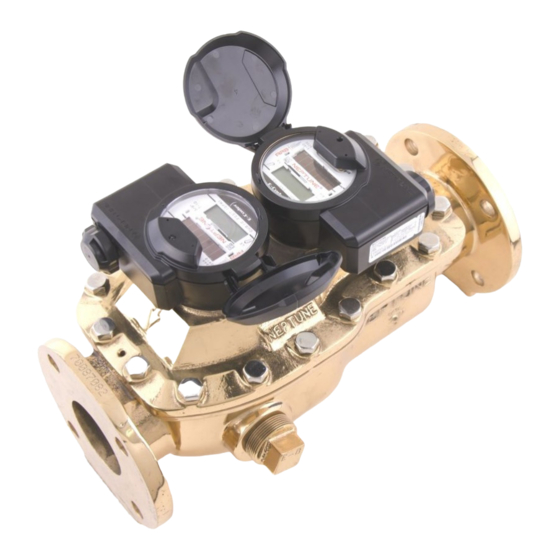
Page 13: Product Description
Product Description The TRU/FLO meter is designed to register wide flow ranges where varying flow rates are typical. It combines the low flow sensitivity of a disc-type meter with the high flow capacity of a turbine-type meter. Its key features include: •... -
Page 14: Tru/Flo General Information
Construction The TRU/FLO meter consists of a durable lead free, high-copper alloy maincase, Neptune turbine measuring assembly, Neptune T-10 chamber, and two magnetic-driven, roll-sealed registers. The lead free, high-copper maincase is corrosion-resistant and easy to handle. - Page 15 2,700,000 gallons 8,000,000 2 years or 2,700,000 gallons The HP Turbine and turbine side of the TRU/FLO compound water meters performs, for a period of one year from the date of shipment, to AWWA accuracy standards for new water meters.
-
Page 16: Specifications
150 PSI (1034 KPA) Maximum Operating Temperature of Water 80º F TRU/FLO Operating Characteristics This section provides a table of the operating characteristics of the TRU/FLO meter. Table 3 Operating Characteristics Normal Operating Range @100% TRU/FLO Meter Size Accuracy (±1.5%) -
Page 17: Tru/Flo Dimensions
Specifications TRU/FLO Dimensions This section provides the dimensions, diagrams, and registration of the TRU/FLO meter. Table 4 Dimensions TRU/FLO E-Coder)R900i Flange Type Weight Meter Size in/mm in/mm in/mm in/mm in/mm in/mm in/mm in/mm in/mm lbs/kg 2-inch HP 15¼ 8⅝ 12⅛... - Page 18 1,000,000,000 1,000,000,000 100,000,000 10,000,000 Disc Side 2” 10,000,000 10,000,000 1,000,000 100,000 3” 10,000,000 10,000,000 1,000,000 100,000 4” 10,000,000 10,000,000 1,000,000 100,000 6” 10,000,000 10,000,000 1,000,000 100,000 6” x 8” 10,000,000 10,000,000 1,000,000 100,000 TRU/FLO Compound Meter Installation and Maintenance Guide...
-
Page 19: General Installation Guidelines
Complete the following safety and preliminary checks before and during each installation: • Verify that you are at the location specified on the Site Work Order. • Verify that the site is safe for you and your equipment. TRU/FLO Compound Meter Installation and Maintenance Guide... -
Page 20: Prior To Installation
Once the inspection is complete, store the cartons in a clean, dry environment. Unpacking The TRU/FLO meter is heavy and needs to be handled carefully. Lift the assembly out of the box by the meter maincase, and not by the register. Inspect the meter for damage but use caution;... -
Page 21: Installing The Tru/Flo
The upstream plate-type strainer provides protection against meter damage from debris in the lines and minimizes the effects of variation in upstream piping. Use of a Neptune strainer of the same line size as the meter is specifically recommended. This strainer design provides optimum velocity profile correction at minimum additional head loss. - Page 22 TRU/FLO meters must operate in a completely filled line at all times. The downstream piping must always provide sufficient back pressure to maintain a full line at the meter.
-
Page 23: Ensuring Proper Installation
Installing the TRU/FLO Ensuring Proper Installation After the TRU/FLO meter is installed, you must carefully fill the meter with water. Complete the following steps: Make sure the service line has been flushed of any debris before installing the meter. Turn the bleed screw (located on the cover) counter-clockwise one to two turns. -
Page 24: Maintaining The Tru/Flo Compound Meter
5 Maintaining the TRU/FLO Compound Meter This chapter provides instructions for maintaining the TRU/FLO meter. The 3-inch, 4- inch, and 6-inch meters in the TRU/FLO product line share similar features and functions. TRU/FLO meters are composed of four major components: •... -
Page 25: Neptune's Ume Design
• For a TRU/FLO meter, this includes the bronze cover with the two registers, the T-10 chamber, and the turbine measuring assembly. For the HP Turbine, HP PROTECTUS III, and Fire Hydrant, this includes the register, bronze cover, and the turbine measuring assembly. -
Page 26: Removing The Cover Assembly
Remove the seal pins from the register. The seal pin can be removed with a screw driver as indicated in Figure 8. Figure 8 Remove Seal Pin Remove the registers from the TRU/FLO cover assembly. See Figure 9. Lay the registers aside in an upright position. -
Page 27: Reinstalling The Cover Assembly
The maincase gasket does not need to be secured with any adhesive. Place the cover assembly on the maincase, making sure that the cover assembly aligns with the guide pins. See Figure 13 Guide pin Figure 13 Placing the Cover Assembly TRU/FLO Compound Meter Installation and Maintenance Guide... -
Page 28: Performing Maintenance On The T-10 Chamber
Removing the T-10 Chamber Complete the following steps to remove the T-10 chamber. Remove the cover assembly. See “Removing the Cover Assembly” on page 14. Remove the T-10 plate. See Figure 16. Figure 16 T-10 Plate TRU/FLO Compound Meter Installation and Maintenance Guide... - Page 29 See Figure 19. Inspect the chamber for any damage, and if necessary discard the chamber. Breaking down and rebuilding individual components in the chamber is not recommended. T-10 chamber Figure 19 Removing the T-10 Chamber TRU/FLO Compound Meter Installation and Maintenance Guide...
- Page 30 See Figure 22. Lightly clean all areas that touch magnetic components. Do not rub too hard or you could permanently damage the machined metal surface. Figure 22 Cleaning Under the Registers TRU/FLO Compound Meter Installation and Maintenance Guide...
-
Page 31: Replacing The T-10 Chamber
Figure 24 Placing the T-10 Chamber Add the chamber gasket to the T-10 chamber. See Figure 25 and Figure 26. Figure 25 T-10 Chamber Gasket Figure 26 Replacing the Gasket TRU/FLO Compound Meter Installation and Maintenance Guide... -
Page 32: Performing Maintenance On The Turbine Measuring Assembly
Place the cover assembly on its side with the turbine measuring assembly facing you. Use the 7/16-inch wrench to remove the calibration vane lock nut. See Figure 29. Keep the bolts for later use. Figure 29 Removing the Lock Nuts TRU/FLO Compound Meter Installation and Maintenance Guide... - Page 33 Figure 31 Removing the Lock Nuts Remove the turbine measuring assembly by lifting the magnet drive spindle and the calibration vane assembly up. See Figure 32. Calibration vane assembly Figure 32 Removing the Rotor Assembly TRU/FLO Compound Meter Installation and Maintenance Guide...
-
Page 34: Replacing The Turbine Measuring Assembly
Return the calibration vane assembly to the turbine measuring assembly. Install the calibration vane so that the large portion of the vane is inside of the measuring assembly. Replace or re-install the magnetic drive assembly. Figure 35 Magnet Drive Assembly TRU/FLO Compound Meter Installation and Maintenance Guide... -
Page 35: Setting The Calibration Vane Assembly
The calibration vane assembly can be modified to change the registration of the meter. You can either turn the calibration vane to the positive side to increase registration or to the negative side to decrease registration. TRU/FLO Compound Meter Installation and Maintenance Guide... -
Page 36: Performing Maintenance On The Throttle Valve Assembly
Complete the following steps to remove the throttle valve assembly. Lift the throttle valve assembly, then insert the snap ring pliers. Use the pliers to remove the snap ring. See Figure 41. Figure 41 Removing the Snap Ring TRU/FLO Compound Meter Installation and Maintenance Guide... -
Page 37: Replacing The Throttle Valve Assembly
Lift the throttle valve up and place the snap ring in the throttle valve groove. The snap ring locks the throttle valve assembly in place and can be reused. Main valve assembly Throttle valve flap Figure 43 Placing the Throttle Valve Assembly TRU/FLO Compound Meter Installation and Maintenance Guide... -
Page 38: Performing Maintenance On The Main Valve Assembly
Use your hand or the screwdriver to walk around the snap and then remove the snap ring from the meter. See Figure 46. Keep the main valve snap ring for later use. Figure 46 Remove the Snap Ring TRU/FLO Compound Meter Installation and Maintenance Guide... -
Page 39: Replacing The Main Valve Assembly
The brass is sharp. Handle with care or wear durable gloves to avoid cuts and abrasions. Check and make sure the main valve snap ring is in the groove. Main valve snap ring Figure 49 Attaching the Main Valve Snap Ring TRU/FLO Compound Meter Installation and Maintenance Guide... -
Page 40: Why Maintenance Is Important
Below are some generic guidelines for performing a meter accuracy test. For more information, consult the TRU/FLO Field Testing Guide or AWWA’s M6 manual. - Page 41 90% in the crossover range. The crossover range can also cover a small flow range. For more details see AWWA C702. For more information, please consult the TRU/FLO Field Testing Guide and AWWA’s M6 manual. TRU/FLO Compound Meter Installation and Maintenance Guide...
- Page 42 Why Maintenance is Important Notes: TRU/FLO Compound Meter Installation and Maintenance Guide...
-
Page 43: Strainer Cleaning And Maintenance
Appendix A: Strainer Cleaning and Maintenance This section provides information on how to clean and maintain the TRU/FLO strainer. Cleaning the Strainer To clean the strainer, complete the following steps. First remove the cover. Pull the metal strainer out of the body and clean off any build up of debris. - Page 44 Appendix A Notes: TRU/FLO Compound Meter Installation and Maintenance Guide...
-
Page 45: Tru/Flo Parts List
Appendix B: TRU/FLO Parts List This appendix describes the individual parts that makeup the TRU/FLO meter. 2-inch Meter The following diagram is a representative breakdown of the 2-inch meter. Table 8 on page 34 describes each part of the diagram. - Page 46 Bolt, 3/8 - 16 UNC - 2A x 1¼-inch LG., SS 316 Retainer Ring Cover Assembly Screw, #10 - 24 x 1-inch, Pan Recessed, SS 18-8 Roll Pin Strainer Pipe Plug - 1½-inch TRU/FLO Compound Meter Installation and Maintenance Guide...
-
Page 47: 3-Inch, 4-Inch And 6-Inch Meters
The following diagram is a representative breakdown of the 3-inch, 4-inch and 6-inch meters. Table 9 on page 36 describes each part of the diagram. Figure 52 Representative Breakdown of the 3-inch, 4-inch, and 6-inch TRU/FLO Meter Components TRU/FLO Compound Meter Installation and Maintenance Guide... - Page 48 Appendix B Table 9 3-inch, 4-inch and 6-inch TRU/FLO Parts List Item Description Item Description Item Description Cover Assembly Bolt Cover Plate Maincase Gasket Vent Screw Screw Maincase Gasket Kit Seal Wire with Lead Seal Bolt Snap Ring Seal Cap...
-
Page 49: 2-Inch Tru/Flo Maintenance
This appendix provides information on maintenance for the 2-inch meter. Removing the UME Complete the following steps. Remove the bolts around the perimeter of the cover. Separate the cover assembly from the maincase. See Figure 53. Figure 53 Remove the UME TRU/FLO Compound Meter Installation and Maintenance Guide... -
Page 50: Performing Maintenance On The Internal Strainer
Remove the retainer ring from the inlet of the main valve assembly. See Figure 56. Inside you can see an o-ring that seals the main valve assembly. Retainer ring Figure 56 Remove Retainer Ring TRU/FLO Compound Meter Installation and Maintenance Guide... - Page 51 See Figure 58. Figure 58 Reinstalling the Parts Reinstall the retainer ring on the main valve and tighten the four screws. See Figure 59. Figure 59 Secure Retainer Ring TRU/FLO Compound Meter Installation and Maintenance Guide...
-
Page 52: Performing Maintenance On The Throttle Valve
Figure 62 Removing the Throttle Valve. Maintenance on the turbine and disc side of the meter is accomplished in the same manner shown previously in this document for the 3-inch, 4-inch and 6-inch meters. TRU/FLO Compound Meter Installation and Maintenance Guide... -
Page 53: Glossary
Rocking, swaying, or nodding motion in the axis of rotation of a largely axially symmetric object. TRU/FLO Compound Meter Installation and Maintenance Guide... - Page 54 Stainless steel assembly found on the outlet of the T-10 measuring chamber. It is used to regulate the flow that moves through the T-10 chamber as the TRU/FLO’s overall flow rate increases. As the flow increases through the TRU/FLO, the main valve assembly seals off the throttle valve.
-
Page 55: Index
43 operation 2 flow conditions 9 o-ring 18, 19, 22 gasket 10 plate, strainer 9 chamber 19 kit 7 gate valve 11 registers 2, 14, 16 guide pins 15 registration TRU/FLO Compound Meter Installation and Maintenance Guide... - Page 56 7 T-10 chamber 2, 12, 13, 16, 19, 29 velocity profile 9 removing 16 replacing 19 T-10 plate 16 warranty 2 T-10 plate gasket 17 T-10 strainer 17, 19, 29 TRU/FLO Compound Meter Installation and Maintenance Guide...
- Page 58 Fax: (905) 858-0428 Tel: +(525) 5203 5294 / +(525) 5203 4032 TAKE CONTROL Fax: +(525) 5203 6503 neptunetg.com IM TRU/FLO 08.15 Part No. 13505-001 © Copyright 2015, Neptune Technology Group Inc. Neptune is a registered trademark of Neptune Technology Group Inc.
Need help?
Do you have a question about the TRU/FLO and is the answer not in the manual?
Questions and answers