Table of Contents
Advertisement
Advertisement
Table of Contents

Related Manuals for Neptune MACH 10


Summary of Contents for Neptune MACH 10
- Page 1 ® MACH 10 Ultrasonic Meter Installation and Maintenance Guide...
- Page 3 ® MACH 10 Ultrasonic Meter Installation and Maintenance Guide...
- Page 4 Neptune Technology Group Inc. Neptune engages in ongoing research and development to improve and enhance its products. Therefore, Neptune reserves the right to change product or system specifications without notice. Trademarks Used in this Manual ®...
- Page 5 Changes or modifications not expressly approved by the party responsible for compliance could void the users' authority to operate the equipment. Professional Installation In accordance with section 15.203 of the FCC rules and regulations, the MIU must be professionally installed by trained meter installers. Changes or modifications not expressly approved by the party responsible for compliance void the user's authority to operate the equipment.
- Page 6 ® MACH 10 Ultrasonic Meter Neptune Technology Group Inc. Installation and Maintenance Guide 1600 Alabama Highway 229 Literature No. IM MACH 10 12.18 Tallassee, AL 36078 Part No. 13505-051 Tel: (800) 633-8754 Fax: (334) 283-7293 Copyright © 2003 - 2018 Neptune Technology Group Inc.
-
Page 7: Table Of Contents
Safety and Preliminary Checks Installation and Application Considerations Water Temperature Meter Installation Water Flow Meter Sizing and Selection ® Chapter 4: Installing MACH 10 Ultrasonic Meters Installation Instructions for MACH 10 ® Meters New Meter Installation Wiring the MACH 10 ®... - Page 8 Contents ® Chapter 5: Activating and Reading MACH 10 Ultrasonic Meters Activating the LCD Meter Display Timeout Period Meter Display LCD Panel How to Read the Meter Alarms LCD Icons Consumption and Unit of Measure Rate of Flow Flow Direction...
- Page 9 Contents Environmental Conditions Functional Specifications Dimensions ® Appendix B: MACH 10 )R900i™ Flags Glossary Index ® MACH 10 Installation and Maintenance Guide...
- Page 10 Contents This page intentionally left blank ® viii MACH 10 Installation and Maintenance Guide...
- Page 11 ® Figure 13 – MACH 10 Faceplate ® Figure 14 – MACH 10 LCD Panel ® Figure 15 – MACH 10 )R900i™ Top View ® Figure 16 – MACH 10 )R900i™ Side View MACH 10 ® Installation and Maintenance Guide...
- Page 12 Figures This page intentionally left blank. ® MACH 10 Installation and Maintenance Guide...
- Page 13 Table 15 – MACH 10 )R900i ™ Dimensions Table 16 – Eighth Digit Resolution by Meter Size ® Table 17 – MACH 10 )R900i™ Flags (digits) ® Table 18 – MACH 10 )R900i™ Flags (minutes) MACH 10 ® Installation and Maintenance Guide...
- Page 14 Tables This page intentionally left blank MACH 10 ® Installation and Maintenance Guide...
-
Page 15: Chapter 1: Product Description
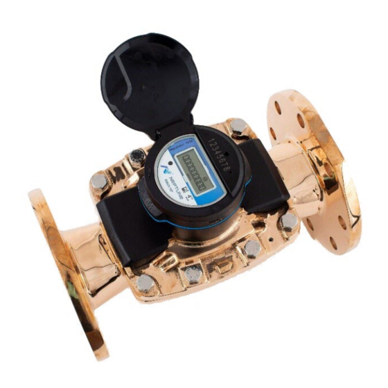
Ultrasonic Meter (MACH 10). Introduction The MACH 10 solid state meter uses ultrasonic transit-time technology and solid state electronics. The meter is contained in a compact, totally encapsulated, weatherproof, and ultraviolet (UV) resistant housing for residential and light commercial applications. Ultrasonic... -
Page 16: Understanding Ultrasonic Technology
Transit-Time Technology The MACH 10 utilizes transit-time ultrasonic technology. This technology takes advantage of the principle that an acoustic signal travels faster with the flow than against the flow of the fluid. These meters have a pair of transducers that are essentially transceivers, sending and receiving the acoustic signals. -
Page 17: Summary
It is totally self-contained. The battery, processor circuit, and electronic display are fully potted and permanently sealed as an integral unit. The MACH 10 meter provides an E-CoderPLUS output signal to Neptune R900 and other AMR / AMI endpoints. - Page 18 Chapter 1: Product Description This page intentionally left blank. MACH 10 ® Installation and Maintenance Guide...
-
Page 19: Specifications
® Chapter 2: MACH 10 Specifications ® This chapter provides the specifications for the MACH 10 Ultrasonic Meter. Environmental and Performance Specifications This table defines environmental specifications that apply to both the Residential and Intermediate MACH 10 meters. Table 1 – Environmental Specifications... -
Page 20: Weight And Dimension Specifications
® Chapter 2: MACH 10 Specifications Weight and Dimension Specifications The following tables define the weight and dimension specifications for the Residential and Intermediate MACH 10 meters. Table 3 – MACH 10 ® Meter Weight Specifications Meter Size Weight Residential 5/8"... -
Page 21: Table 4 - Residential Mach
Chapter 2: MACH 10 ® Specifications ® Table 4 – Residential MACH 10 Dimensions Meter Size D NPSM 5/8" 7-1/2" 4-7/8" 2-1/2" 3/4" – 14 5/8" x 3/4" 7-1/2" 4-7/8" 2-1/2" 1" – 11-1/2 3/4" 9" 4-7/8" 2-9/16" 1" – 11-1/2 3/4"... -
Page 22: Additional Specifications
3.6 volt lithium thionyl-chloride; battery is fully encapsulated within the register housing and is not replaceable Fluid Compatibility The MACH 10 meter is designed and calibrated for potable, combination potable and fire service, and reclaimed water across the defined temperature and velocity range. Maincase The meter maincase is manufactured using lead free bronze, and contains the wetted elements of the meter: two transducers, pressed in reflections, and the flow conditioner. -
Page 23: Battery Requirement
Meter Interface Unit (MIU) requires a battery to perform its functions. With the continued improvements made in battery technology, electronic metering utilizing internal batteries is practical today. The MACH 10 uses lithium thionyl-chloride battery technology. ®... -
Page 24: Chapter 2: Mach
Chapter 2: MACH 10® Specifications This page intentionally left blank. MACH 10 ® Installation and Maintenance Guide... -
Page 25: Chapter 3: General Installation Guidelines
MACH 10 Tools and Materials show the recommended tools and materials you need to successfully Table 7 Table 8 install the MACH 10. are not complete lists of tools and materials. Table 7 Table 8 Table 7 – Recommended Tools... -
Page 26: Safety And Preliminary Checks
Notify the customer of your presence, and tell the customer that you need access to the water meter. Write the ID numbers of the MACH 10 meters you are about to install on the site work order. If the site work order already has a MACH 10 ID number, verify that it matches the ID numbers on the MACH 10 you are about to install. -
Page 27: Chapter 4: Installing Mach 10 ® Ultrasonic Meters
® Installation Instructions for MACH 10 Meters This section defines the step-by step instructions for installing the MACH 10 meter. In outdoor settings, the meter and service line should be located deep enough in the ground to prevent freezing. New Meter Installation The following are steps for installation of the MACH 10 meter. -
Page 28: Wiring The Mach
Wiring the MACH 10 The following table defines the steps to wire the MACH 10 meter while you are in the field. If the meter is not a MACH 10 prewired and potted to an MIU, complete the following steps to wire the MACH 10. -
Page 29: Figure 7 - Ur Crimping Tool
8. Repeat steps 1 through 5 for each color wire. Figure 8 – Improper Connections Table 9 – Color Codes for Wires MIU Wire Color / MACH 10 Wire Color MIU Type R900 Black/B Green/G Red/R Black/G Green/R ... -
Page 30: Completing The Wiring
Black/G Green/R Red/B Badger Completing the Wiring The following table outlines the steps to wire the MACH 10. 1. After you connect all three color wires, read the encoder register to ensure proper connections and the receptacle / MIU is functioning properly. -
Page 31: Figure 11 - Gray Wires In Slot
Chapter 4: Installing MACH 10 ® Ultrasonic Meters 3. Separate each gray wire and place them into the slots on each side. Figure 11 – Gray Wires in Slot 4. Snap the cover closed to finish the installation. Figure 12 – Cover in Place ®... - Page 32 Chapter 4: Installing MACH 10® Ultrasonic Meters This page intentionally left blank. MACH 10 ® Installation and Maintenance Guide...
-
Page 33: Chapter 5: Activating And Reading Mach 10 ® Ultrasonic Meters
This chapter explains the operations of the MACH 10 ultrasonic meter. Activating the LCD Meter Display The light sensor is located in the center of the faceplate of the MACH 10, and it supplies the power for the Liquid Crystal Display (LCD) panel. ®... -
Page 34: Lcd Panel
® Chapter 5: Activating and Reading MACH 10 Ultrasonic Meters LCD Panel Following is an example of the MACH 10 LCD panel. The table on the following page provides a description of each icon. ® Figure 14 – MACH 10... -
Page 35: Lcd Icons
Chapter 5: Activating and Reading MACH 10® Ultrasonic Meters LCD Icons The following table defines the MACH 10 LCD icons and the status they indicate. ® Table 10 – MACH 10 Icons and Displays Icon Description Status Explanation Leak Icon used to indicate a leak. Leak Number of 15-minute intervals <... -
Page 36: Consumption And Unit Of Measure
® Chapter 5: Activating and Reading MACH 10 Ultrasonic Meters Consumption and Unit of Measure The consumption display contains all nine digits, including leading zeros and a decimal point. The value displayed is the sum of the forward flow minus the reverse flow. -
Page 37: Amr / Ami Output
Ultrasonic Meters AMR / AMI Output The Neptune MACH 10 ultrasonic meter is a compact design where the electronic register is fully potted and permanently sealed to the meter maincase. The meter provides high resolution E-CoderPLUS protocol. It communicates status indicators to Neptune R900 RF endpoints as part of the extended encoder / meter reading message. - Page 38 Chapter 5: Activating and Reading MACH 10 ® Ultrasonic Meters This page intentionally left blank. MACH 10 ® Installation and Maintenance Guide...
-
Page 39: Chapter 6: Maintenance And Troubleshooting
At the end of the meter's life, the meter is simply replaced. Replacement Parts There are no replacement parts for the MACH 10 ultrasonic meter. If the plastic meter lid becomes damaged or broken, it can be replaced. Troubleshooting Some conditions such as the following can occur. -
Page 40: Contact Information
A description of any actions taken to correct the issue By Fax To contact Neptune Customer Support by fax, send a description of your problem to (334) 283-7497. Please include on the fax cover sheet the best time of day for a customer support specialist to contact you. -
Page 41: Appendix A: Mach 10 ® )R900I
The transmitted data is updated at 15-minute intervals. It transmits a mobile message that includes the meter reading data and the unique 10-digit MACH 10 ID every 14 to 20 seconds. This allows the meter to be read by a hand held unit (HHU) or mobile data collection unit. -
Page 42: Mach 10 ® )R900I™ Specifications
910 to 920 MHz Output Power Meeting FCC Part 15.247 FCC Verification Part 15.247 Environmental Conditions The following table defines the optimal environmental conditions for the MACH 10. Table 13 – Environmental Conditions Condition Description Operating temperature 14° to 149°F (–10° to +65°C) Storage temperature –40°... -
Page 43: Dimensions
Appendix A: MACH 10 ® )R900i™ Dimensions The dimensions of the MACH 10 are shown in the following images and on page 30. ® Figure 15 – MACH 10 )R900i™ Top View ® Figure 16 – MACH 10 )R900i™ Side View ®... -
Page 44: Table 15 - Mach 10 )R900I ™ Dimensions
® Appendix A: MACH 10 )R900i™ The following tables define the dimensions of the Residential MACH 10 meters. ® Table 15 – MACH 10 )R900i ™ Dimensions Meter D NSPM (external antenna) 5/8" 7-1/2" 6-3/4" 2-1/2" 3/4" - 14 5-7/8"... -
Page 45: Appendix B: Mach
Appendix B: MACH 10 )R900i™ Flags The three tables in this appendix describe the volume represented by the eighth digit by ® meter size (Residential and Intermediate), and the flags used by the MACH 10 )R900i (digits) ® and MACH 10 )R900i (minutes). - Page 46 ® Appendix B: MACH 10 )R900i™ Flags ® Table 18 – MACH 10 )R900i™ Flags (minutes) Leak Status Flag (Resets After 35 Days) Based on total amount of 15-minute periods recorded in the previous 24-hour period. Leak icon off Eighth digit incremented less than 50 of the 96 15-minute intervals...
-
Page 47: Glossary
Condition whenever the measurement section of the meter is not completely filled with water. Liquid Crystal Display. light sensor Component located under the recess that is used to activate the Liquid Crystal Display (LCD). Meter Interface Unit. ® MACH 10 Installation and Maintenance Guide... -
Page 48: Serial Number
Electronic meter using ultrasonic technology and solid state electronics contained in a compact, totally encapsulated, weatherproof, and ultraviolet (UV) resistant housing for residential and light commercial applications. ® MACH 10 Installation and Maintenance Guide... - Page 49 Glossary Vmin Change the ninth digit of the LCD. This is factory programmed depending on meter size. ® MACH 10 Installation and Maintenance Guide...
- Page 50 Glossary This page intentionally left blank. ® MACH 10 Installation and Maintenance Guide...
-
Page 51: Index
23 flags 31 flashlight 11 flow calculated velocity 3 direction 22 calibrated 12 rate 12 checks preliminary 12 safety 12 grounding strap 13 conductive 2 connections 16 hopping, frequency 27 consumption 19, 22 ® MACH 10 Installation and Maintenance Guide... - Page 52 Subterm 8, 21, 28 panel 20 output 23 leakage 13 light sensor 19 piezoelectric 8 piping 12 ® MACH 10 potted 3, 23 R900i 27 product description 1 flags 31 programming 27 rate of flow 22 specifications 28 reading resolution 23...
- Page 53 27 protocol error 27 sealed 3 service line 13 temperature water 12 Term See Other Term, Subterm toolkit 11 transceivers 2 transducers 2, 8 transit-time 2 troubleshooting 25 valve 13 inlet 13 outlet 14 ® MACH 10 Installation and Maintenance Guide...
- Page 55 ® IM MACH 10 12.18 Part No. 13682-001 © Copyright 2003-2018, Neptune Technology Group Inc. Neptune is a registered trademark of Neptune Technology Group Inc.
Need help?
Do you have a question about the MACH 10 and is the answer not in the manual?
Questions and answers