Table of Contents
Advertisement
Quick Links
Advertisement
Table of Contents

Related Manuals for Neptune HP PROTECTUS III


Summary of Contents for Neptune HP PROTECTUS III
- Page 1 HP PROTECTUS ® III Installation and Maintenance Guide...
- Page 3 ® HP PROTECTUS Installation and Maintenance Guide...
- Page 4 Copyright This manual is an unpublished work and contains the trade secrets and confidential information of Neptune Technology Group Inc., which are not to be divulged to third parties and may not be reproduced or transmitted in whole or part, in any form or by any means, electronic or mechanical for any purpose, without the express written permission of Neptune Technology Group Inc.
- Page 5 RF Exposure Information This equipment complies with the FCC RF radiation requirements for uncontrolled environments. To maintain compliance with these requirements, the antenna and any radiating elements should be installed to ensure that a minimum separation distance of 20 cm is maintained from the general population.
- Page 6 Neptune Technology Group Inc. ® HP PROTECTUS III Installation and Maintenance Guide 1600 Alabama Highway 229 Literature No. IM HP PROTECTUS III 10.19 Tallassee, AL 36078 Part No. 13505-021 Tel: (800) 633-8754 Fax: (334) 283-7293 Copyright © 2006 - 2019 Neptune Technology Group Inc.
-
Page 7: Table Of Contents
Contents Chapter 1: Product Description Components Turbine Measuring Element T-10 Bypass ® Throttle Valve Knuckle Valve UL / FM Basket Strainer HP PROTECTUS III General Information ® Operation Construction Warranty Chapter 2: Specifications Environmental Specifications HP PROTECTUS III Operating Characteristics ®... - Page 8 Contents Chapter 4: Maintenance and Troubleshooting Neptune's UME Design Performing Meter Maintenance Low Side T-10 ® Reassemble the T-10 ® High Side - HP Turbine Inspect the Basket Strainer Flush the Strainer Body Knuckle Valve Removing the Knuckle Valve Setting the Spring of the Knuckle Valve...
- Page 9 Figures Figure 1 – HP PROTECTUS III ® Figure 2 – HP PROTECTUS III Side View ® Figure 3 – HP PROTECTUS III Top View ® Figure 4 – HP PROTECTUS III End View ® Figure 5 – Calibration Vane Figure 6 –...
- Page 10 Figures Figure 28 – Installing the Register Figure 29 – Strainer Top Plate Figure 30 – Strainer Top Plate Hook Figure 31 – Basket Strainer Figure 32 – Inspecting the Basket Figure 33 – Pipe Plug Figure 34 – Replacing the Basket Figure 35 –...
- Page 11 Figures Figure 57 – Victaulic Coupling Gasket ® Figure 58 – Separating the Strainer Figure 59 – New Gasket Figure 60 – Reattaching the Coupling Figure 61 – Tightening the Bolts Figure 62 – HP PROTECTUS III Parts Diagram ® ®...
- Page 12 Figures This page intentionally left blank. ® HP PROTECTUS III Installation and Maintenance Guide...
- Page 13 Tables Table 1 – Environmental Specifications Table 2 – Operating Characteristics Table 3 – HP PROTECTUS III Dimensions - Side View ® Table 4 – HP PROTECTUS III Dimensions - Top and End View ® Table 5 – Meter Registration for the Six-Wheel Odometer Table 6 –...
- Page 14 Tables This page intentionally left blank HP PROTECTUS ® III Installation and Maintenance Guide...
-
Page 15: Chapter 1: Product Description
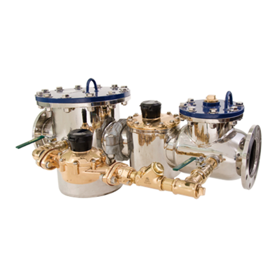
High Performance (HP) PROTECTUS III Fire Service Meter. The HP PROTECTUS III meter measures both domestic and fire service water usage through a single water line. The HP PROTECTUS III meter measures extremely wide flow ranges ®... -
Page 16: Components
T-10 bypass. The valve protects the T-10 from excessive usage and facilitates the meter’s transition through crossover. Do not replace the T-10 on an HP PROTECTUS III bypass with a T-10 meter that does not have the throttle valve installed in the T-10 outlet. Make sure the throttle valve is present in the outlet of the meter used. -
Page 17: Knuckle Valve
The turbine measuring element can register flow when the rate is medium to high. UL / FM Basket Strainer The strainer in the HP PROTECTUS III meter is a UL / FM-approved strainer specially designed to handle fire service applications. The round style of the strainer allows debris to fall to the bottom of the strainer housing. -
Page 18: Construction
The stainless steel body is warranted for 20 years, 10 of which are prorated. Neptune fire service cold water meters perform for a period of one year from date of shipment, to American Water Works Association (AWWA) accuracy standards for new water meters. -
Page 19: Chapter 2: Specifications
Operating Pressure 175 psi (1206 kPa). Maximum Operating Pressure 175 psi (1206 kPa). ® HP PROTECTUS III Operating Characteristics The following table contains the operating characteristics of the HP PROTECTUS III meter. Table 2 – Operating Characteristics Normal Operating Maximum Meter Low Flow @... -
Page 20: Figure 1 - Hp Protectus
Chapter 2: Specifications ® HP PROTECTUS III Dimensions The following tables provide the dimensions, diagrams, and registration of the HP PROTECTUS III meter. Table 3 – HP PROTECTUS III Dimensions - Side View ® Meter Size A in / mm B in / mmg C in / mmg D in / mm... -
Page 21: Figure 2 - Hp Protectus
Chapter 2: Specifications Table 4 – HP PROTECTUS III Dimensions - Top and End View ® Meter Weight lbs / F in / mm G in / mmg H in / mmg I in / mm J in / mm Size 4 inch 15-1/4 / 387... -
Page 22: Table 5 - Meter Registration For The Six-Wheel Odometer
Chapter 2: Specifications Table 5 – Meter Registration for the Six-Wheel Odometer Meter Size US Gallon Imperial Gallon Cubic Feet Cubic Meters Disc Side 1 inch 1-1/2 inch 2 inch Turbine Side 4 inch 6 inch 1,000 1,000 8 inch 1,000 1,000 10 inch... -
Page 23: Chapter 3: Installing The Hp Protectus
This chapter steps you through installing the HP PROTECTUS III meter. Prior to Installation This section defines how to unpack and store the HP PROTECTUS III before you install it. Storage Upon receipt, inspect the shipping containers for damage and inspect the contents of any damaged cartons before storing. -
Page 24: Safety And Preliminary Checks
When installing the Neptune HP PROTECTUS III, a minimum of four pipe diameters of straight run pipe can include components that are fully open in their normal operating position. -
Page 25: Recommended Installation
® Recommended Installation You can lower the HP PROTECTUS III meter assembly into the meter vault and put it in place using chains or straps. Attach the chains or straps to the lifting hooks on the top of both the strainer and knuckle valve. -
Page 26: Adjusting The Calibration Vane
® Adjusting the Calibration Vane Neptune equips all new turbine meters and UMEs with a calibration vane. If field calibration of the turbine element is required, complete the following steps. 1. Remove the seal pin from the register and twist off the register. -
Page 27: Before Operation
Chapter 3: Installing the HP PROTECTUS ® Before Operation Before putting the HP PROTECTUS III meter assembly into service, complete the following steps. 1. Close all valves. 2. Turn the air bleed screw on the knuckle valve and strainer cover counter-clockwise one to two turns. - Page 28 Chapter 3: Installing the HP PROTECTUS ® This page intentionally left blank. ® HP PROTECTUS III Installation and Maintenance Guide...
-
Page 29: Chapter 4: Maintenance And Troubleshooting
This chapter provides instructions for maintaining the HP PROTECTUS III meter. The 4-inch, 6-inch, 8-inch, and 10-inch meters in the HP PROTECTUS III product line share similar features and functions. HP PROTECTUS III meters are composed of five major components: HP PROTECTUS III turbine measuring element. -
Page 30: Figure 8 - Unitized Measuring Element (Ume)
Figure 8 – Unitized Measuring Element (UME) 7. Replace and tighten the cover bolts. Before putting the HP PROTECTUS III back into service, complete the following steps. 1. Turn the air bleed screw on the detector knuckle valve and strainer cover counter- clockwise one to two turns. -
Page 31: Performing Meter Maintenance
Chapter 4: Maintenance and Troubleshooting Performing Meter Maintenance This section provides information on maintaining the HP PROTECTUS III meter. Always wear protective eye wear when working with any product. There are two sides to the HP PROTECTUS III meter: Low side, T-10. -
Page 32: Figure 9 - Removing The
Chapter 4: Maintenance and Troubleshooting 2. Break the register seal pin and remove the register from the top plate of the T-10. Take a small screw driver and drive it into the seal pin. Figure 10 – Removing the Register 3. -
Page 33: Figure 13 - Removing The
Chapter 4: Maintenance and Troubleshooting 5. Remove the T-10 strainer. Insert the screw driver between the strainer and disc chamber and lift straight up. Tabs are located on top of the strainer for easier removal. Wedge the screwdriver underneath these tabs and lift the strainer straight up. Inspect the strainer and remove any debris. -
Page 34: Reassemble The
Chapter 4: Maintenance and Troubleshooting 7. Inspect the throttle valve for damage (broken spring) and replace, if needed. Figure 16 – Throttle Valve A replacement T-10 body does not include the throttle valve. Purchase one of the following: - New T-10 with the throttle already installed: P/N 12001-000, 12001-100, or 120010200 depending on size. -
Page 35: Figure 18 - Square O-Ring
Chapter 4: Maintenance and Troubleshooting 2. Replace the square o-ring on the disc chamber. Figure 18 – Square O-Ring 3. Lower the disc chamber into the T-10 meter. Figure 19 – Inserting the Disc Chamber 4. Insert the disc strainer. Line it up with the notches inside the meter and make sure it is flush. -
Page 36: Figure 21 - Inserting The New Gasket
Chapter 4: Maintenance and Troubleshooting 5. Place the new gasket in the main case. Figure 21 – Inserting the New Gasket 6. Lightly clean the machined surface on the top plate with wet or dry sandpaper. Figure 22 – Cleaning the Top Plate 7. -
Page 37: High Side - Hp Turbine
Chapter 4: Maintenance and Troubleshooting Do not mix up the low side and the high side registers. Doing so can cause an inaccurate meter reading. The register on the low side says T-10 on the dial face. The register on the high side says either HP PIII or HPT P3”. -
Page 38: Figure 26 - Removing The Hp Turbine Top Plate
Chapter 4: Maintenance and Troubleshooting 3. Place a screw driver under the HP Turbine cover, in the slots provided to pop the top, and lift up to remove the cover. The UME is exposed. Figure 26 – Removing the HP Turbine Top Plate Not pictured for the 8 inch meter is the valve seal. -
Page 39: Inspect The Basket Strainer
Chapter 4: Maintenance and Troubleshooting Neptune recommends the customer purchase a new UME. This ensures that a factory- tested UME is used as the replacement and the turbine performance is guaranteed. 4. Install a new o-ring on the UME, if needed. See the previous figure. -
Page 40: Figure 30 - Strainer Top Plate Hook
Chapter 4: Maintenance and Troubleshooting 2. Remove the strainer top plate by grasping the hook provided on the top plate. Figure 30 – Strainer Top Plate Hook The top plate is very heavy and could cause serious injury if proper precautions are not taken. -
Page 41: Flush The Strainer Body
Chapter 4: Maintenance and Troubleshooting 4. Inspect the basket for damage (broken welds, dents, or holes) and replace if damaged. Figure 32 – Inspecting the Basket Flush the Strainer Body A pipe plug is located on the opposite side of the strainer housing. To flush the strainer body, complete the following steps. -
Page 42: Figure 34 - Replacing The Basket
Chapter 4: Maintenance and Troubleshooting 3. Insert the basket into the strainer case. Figure 34 – Replacing the Basket 4. Make sure the o-ring is in the groove on the flange of the strainer case and is not damaged. Figure 35 – Strainer Case O-Ring 5. -
Page 43: Knuckle Valve
Chapter 4: Maintenance and Troubleshooting 6. Line up the bolt holes on the top plate to the bolt holes on the strainer body. To prevent the epoxy coat from chipping when installing bolts, place a washer on top of and under the bolt holes. 7. -
Page 44: Figure 39 - Removing The Knuckle Valve Top Plate
Chapter 4: Maintenance and Troubleshooting 2. Use the hook provided to remove the cover off the knuckle valve housing. The knuckle valve is revealed. Figure 39 – Removing the Knuckle Valve Top Plate The top plate is very heavy and could cause bodily harm. Lift the top plate with the hook provided. -
Page 45: Removing The Knuckle Valve
Chapter 4: Maintenance and Troubleshooting Removing the Knuckle Valve To remove the knuckle valve, complete the following steps. 1. Place the knuckle valve top plate back on top of the knuckle valve housing as a safety precaution. 2. Remove the two smaller bolts from the side of the knuckle valve housing until you hear a popping sound. -
Page 46: Figure 43 - Removing The Knuckle Valve
Chapter 4: Maintenance and Troubleshooting 5. Tap the knuckle valve linkages until the valve comes off and falls into the knuckle valve housing. 6. Grip the knuckle valve by the rubber disk and remove it from the housing. Figure 43 – Removing the Knuckle Valve 7. -
Page 47: Setting The Spring Of The Knuckle Valve
Chapter 4: Maintenance and Troubleshooting Setting the Spring of the Knuckle Valve To set the knuckle valve, complete the following steps. 1. Insert the bolts you removed from the side of the knuckle valve housing into the same bolt holes, but install the bolts so that their threads are sticking out of the knuckle valve housing. -
Page 48: Figure 47 - Tool Holes
5. Insert the knuckle valve tool in the tool holes provided to secure the spring. Figure 47 – Tool Holes To purchase the knuckle valve tool, contact Neptune Customer Service and provide one of the following part numbers based on the meter size: - 4 inch - P/N 5500-153. -
Page 49: Installing The New Knuckle Valve
Chapter 4: Maintenance and Troubleshooting Installing the New Knuckle Valve To install the new knuckle valve assembly, complete the following steps. 1. Insert the new knuckle valve in the valve casing with the rubber disc facing the HP Turbine. Figure 49 – Rubber Disc Facing HP Turbine 2. -
Page 50: Figure 51 - Removing The Knuckle Valve Tool
Chapter 4: Maintenance and Troubleshooting 4. Insert a long object like a crowbar into the knuckle valve casing and hook the knuckle valve tool. 5. Lift the knuckle valve tool up and away from the knuckle valve. Figure 51 – Removing the Knuckle Valve Tool 6. -
Page 51: Contact Information
Figure 53 – Securing the Knuckle Valve Top Plate Contact Information Within North America, Neptune Customer Support is available Monday through Friday, 7:00 A.M. to 5:00 P.M. Central Standard Time, by telephone or email. By Phone To contact Neptune Customer Support by phone, complete the following steps. -
Page 52: By Email
A description of what occurred and what you were doing at the time. A description of any actions taken to correct the issue. By Email To contact Neptune Support by email, send your message to support@neptunetg.com. ® HP PROTECTUS III Installation and Maintenance Guide... -
Page 53: Appendix A: Detaching The Basket Strainer
Appendix A: Detaching the Basket Strainer This appendix provides information on how to detach the basket strainer from the ® HP Turbine side of the HP PROTECTUS III. ® Figure 54 – Victaulic Coupling ® HP PROTECTUS III Installation and Maintenance Guide... -
Page 54: Detaching The Strainer
Appendix A: Detaching the Basket Strainer Detaching the Strainer Complete the following steps to detach the basket strainer. 1. Remove the bolts on the top of the coupling. Figure 55 – Removing the Bolts ® 2. Place a screwdriver between the two halves of the Victaulic coupling and work it back and forth until loosened. -
Page 55: Reassembling The Victaulic ® Coupling
Appendix A: Detaching the Basket Strainer 5. Slide the gasket toward the strainer outlet throat. ® Figure 57 – Victaulic Coupling Gasket 6. Separate the strainer from the HP Turbine. Figure 58 – Separating the Strainer ® Reassembling the Victaulic Coupling ®... -
Page 56: Figure 60 - Reattaching The Coupling
Appendix A: Detaching the Basket Strainer 2. Align the HP Turbine with the strainer. 3. Place the two pieces of the Victaulic coupling around the gasket on the outlet throat between the strainer and HP Turbine. Figure 60 – Reattaching the Coupling 4. -
Page 57: Appendix B: Hp Protectus ® Iii Parts
III meter. ® HP PROTECTUS III Diagram The following diagrams are a representative breakdown of the HP PROTECTUS III. "HP PROTECTUS® III Parts List" on the next page describes each part of the diagram. ® Figure 62 – HP PROTECTUS III Parts Diagram ®... -
Page 58: Iii Parts List
Appendix B: HP PROTECTUS III Parts ® ® HP PROTECTUS III Parts List The following table includes the description of each HP PROTECTUS III part in the previous diagram. Table 8 – HP PROTECTUS III Parts List ® Item Description Item Description Meter Cover O-Ring 29. -
Page 59: Cover Assembly
Vent Screw. Oval Gasket. Vent Screw Washer. Adjustable Oval Flange. Test Port Pipe Plug. Cover Assembly The following image shows the parts of the HP PROTECTUS III cover. Table 9 – Cover Assembly Parts Item Description Item Description Cover Assembly. - Page 60 Appendix B: HP PROTECTUS III Parts ® This page intentionally left blank. ® HP PROTECTUS III Installation and Maintenance Guide...
-
Page 61: Glossary
Glossary AWWA American Water Works Association. bleed screw Valve used for allowing accumulations of gas in a liquid to blow off. bypass meter Positive displacement, mutating disc type. It can be piped on the left or right side of the assembly. bypass valve Valve placed to control the flow of liquid through a bypass. - Page 62 Glossary gasket Piece of rubber or some other material that is used to make a tight seal between two parts that are joined together. High Performance. knuckle valve Rubber faced disc that is held closed with the springs or linkages visible. Registration Volume of water that went through the meter, per sweep hand revolution.
- Page 63 Glossary Underwriters Laboratory. Unitized Measuring Element. Victaulic coupling ® A development in which a groove is cut around each end of pipe instead of the usual threads. Two ends of pipe are then lined up and a rubber ring is fitted around the joint. Two semicircular bands, forming a sleeve, are placed around the ring and are drawn together with two bolts, which have a ridge on both edges to fit into the groove of the pipe.
- Page 64 Glossary This page intentionally left blank. HP PROTECTUS ® III Installation and Maintenance Guide...
-
Page 65: Index
Index hook 28 assembly, cover 45 installation, recommended 11 bleed screw 13, 16 bypass knuckle valve assembly 4, 11 installing new 35 meter 2, 15 removing 31 knuckle valve spring 33 calibration vane 12 checks, safety and preliminary 10 materials needed 10 contact information 37 maximum cable lengths 6-8 coupling 40... - Page 66 Index specifications, environmental 5 strainer detach 40 flush the body 27 inspect 25 install 10 top plate 26 T-10 bypass meter 2, 17 ® reassemble 20 replacement 20 tools and materials 9 transmitter specifications 5 turbine high side 23 valve knuckle 3, 15, 29 throttle 2, 15, 20 HP PROTECTUS...
- Page 68 IM HP PROTECTUS ® III 10.19 Part No. 13505-021 © Copyright 2006-2019, Neptune Technology Group Inc. Neptune is a registered trademark of Neptune Technology Group Inc.
Need help?
Do you have a question about the HP PROTECTUS III and is the answer not in the manual?
Questions and answers