
Related Manuals for Neptune MACH 10


Summary of Contents for Neptune MACH 10
- Page 1 ® Commercial and Industrial MACH 10 Ultrasonic Meter Installation and Maintenance Guide...
- Page 3 ® Commercial and Industrial MACH 10 Ultrasonic Meter Installation and Maintenance Guide...
- Page 4 Neptune Technology Group Inc. Neptune engages in ongoing research and development to improve and enhance its products. Therefore, Neptune reserves the right to change product or system specifications without notice. Trademarks Used in This Manual ®...
- Page 5 Professional Installation In accordance with section 15.203 of the FCC rules and regulations, the Neptune Meter Interface Unit (MIU) must be professionally installed by trained meter installers. Changes or modifications not expressly approved by the party responsible for compliance void the user's authority to operate the equipment.
- Page 6 ® Commercial and Industrial MACH 10 Neptune Technology Group Inc. Ultrasonic Meter Installation and Maintenance Guide 1600 Alabama Highway 229 Literature No. IM MACH 10 C&I 06.2020 Tallassee, AL 36078 Part No. 13920-001 Tel: (800) 633-8754 Fax: (334) 283-7293 Copyright © 2020 Neptune Technology Group Inc.
-
Page 7: Table Of Contents
Contents Chapter 1: Product Description Introduction Understanding Ultrasonic Technology Transit-Time Technology Summary Chapter 2: Commercial and Industrial MACH 10 ® Specifications Environmental and Performance Specifications Weight and Dimension Specifications Dimensions Additional Specifications Fluid Compatibility Maincase Transducers Battery Requirement Chapter 3: General Installation Guidelines... - Page 8 Rate of Flow Flow Direction AMR / AMI Output Endpoint Reading Resolution ® Chapter 6: Testing the Commercial and Industrial MACH 10 ® Bench Testing the Commercial and Industrial MACH 10 Meter Meter Accuracy Testing Guidelines Test Bench Setup Procedure...
- Page 9 RF Protocol Error Detection ® MACH 10 )R900i™ Specifications Dimensions – Commercial and Industrial Electrical Specification Transmitter Specifications Functional Specifications ® Appendix B: MACH 10 )R900i™ Flags Glossary Index ® Commercial and Industrial MACH 10 Ultrasonic Meter Installation and Maintenance Guide...
- Page 10 Contents This page intentionally left blank ® viii Commercial and Industrial MACH 10 Ultrasonic Meter Installation and Maintenance Guide...
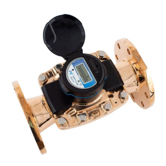
- Page 11 Figure 1 – 3-Inch Commercial and Industrial MACH 10 Ultrasonic Meter ® Figure 2 – Cross-Section of a 3-Inch Commercial and Industrial MACH 10 Figure 3 – Unitized Measuring Element Figure 4 – Commercial and Industrial Meter Dimensions – Side View Figure 5 –...
- Page 12 Figures This page intentionally left blank. ® Commercial and Industrial MACH 10 Ultrasonic Meter Installation and Maintenance Guide...
- Page 13 Table 25 – Eighth Digit Resolution by Meter Size – Commercial and Industrial ® Table 26 – MACH 10 )R900i™ Flags (digits) ® Table 27 – MACH 10 )R900i™ Flags (minutes) Commercial and Industrial MACH 10 ® Ultrasonic Meter Installation and Maintenance Guide...
- Page 14 This page intentionally left blank. Commercial and Industrial MACH 10 ® Ultrasonic Meter Installation and Maintenance Guide...
-
Page 15: Chapter 1: Product Description
(UME) with no degradation of accuracy over time. Combined with a corrosion-resistant, lead free, high-copper alloy maincase, the C&I MACH 10 is built to withstand any demanding service condition and deliver sustained accuracy over the life of the meter. ®... -
Page 16: Understanding Ultrasonic Technology
Transit-Time Technology The MACH 10 utilizes transit-time ultrasonic technology. This technology takes advantage of the principle that an acoustic signal travels faster with the flow than against the flow of the fluid. These meters use transducers that are essentially transceivers, sending and receiving the acoustic signals. -
Page 17: Summary
Summary The MACH 10 meter is a transit-time ultrasonic flow meter with wetted transducers. Designed as an alternative for mechanical meters, the MACH 10 meter utilizes traditional utility pipe connectors and lay lengths. It is totally self-contained. The C&I MACH 10 battery, processor circuit, and electronic display are fully potted and housed in a replaceable UME. -
Page 18: Figure 3 - Unitized Measuring Element
Chapter 1: Product Description ® The MACH 10 meter provides an E-CoderPLUS output signal to Neptune R900 and other ® AMR / AMI endpoints. The MACH 10 )R900i™ contains a MACH 10 meter and an integrated R900 radio for transmitting meter reading data. -
Page 19: Chapter 2: Commercial And Industrial Mach 10
Specifications ® This chapter provides the specifications for the C&I MACH 10 Ultrasonic Meter. Environmental and Performance Specifications This table defines environmental specifications that apply to the C&I MACH 10 meters. Table 1 – Environmental Specifications Specification Description Operating temperature 14°... -
Page 20: Weight And Dimension Specifications
This section defines the dimensions of the Commercial and Industrial MACH 10 meter. Figure 4 – Commercial and Industrial Meter Dimensions – Side View The following table defines the dimensions for the MACH 10 meter. All measurements are in inches. -
Page 21: Additional Specifications
Maincase The C&I MACH 10 meter maincase is manufactured using lead free bronze and is a pressure vessel that supports the UME. The UME is a replaceable assembly that contains all the elements necessary for accurate measurement and registration of water, such as the transducers, battery, electronics, and register. -
Page 22: Transducers
Battery Requirement Solid state metering technologies require a battery to power the transducers and electronics. With the continued improvements made in battery technology, electronic metering utilizing internal batteries is practical today. The MACH 10 uses lithium thionyl-chloride battery technology. ®... -
Page 23: Chapter 3: General Installation Guidelines
Tools and Materials The following tables show the recommended tools and materials you need to successfully install the C&I MACH 10 and replace the Unitized Measuring Element (UME). The tables in this chapter do not contain complete lists of tools and materials. -
Page 24: Safety And Preliminary Checks
Write the ID number of the MACH 10 meter you are about to install on the site work order. If the site work order already has a MACH 10 ID number, verify that it matches the ID number on the MACH 10 you are about to install. -
Page 25: Water Flow
Chapter 3: General Installation Guidelines Water Flow The MACH 10 meter is unable to measure flow when an empty pipe condition is detected. An empty pipe is defined as a condition when the ultrasonic sensors are not fully wetted. In this... -
Page 26: Table 8 - Maximum Flow Rates
Chapter 3: General Installation Guidelines The following table lists the maximum flow rates for the C&I MACH 10 meter. Table 8 – Maximum Flow Rates Meter Size Safe Maximum Operating Capacity 3 inch 500 U.S. gpm 4 inch 1200 U.S. gpm 6 inch 2000 U.S. -
Page 27: Meters
See Table 1 on page 5. Unpacking After unpacking the MACH 10 meter, inspect it for damage. If the meter appears to be damaged, notify your Neptune territory manager or distributor. If a meter requires reshipment, use the original cardboard box and packing material. -
Page 28: Upstream And Downstream Requirements
Ultrasonic Meters Upstream and Downstream Requirements Neptune is in the process of characterizing the performance of the MACH 10 meter under various upstream and downstream installation configurations, such as with the use of strainers, elbows, gate valves, and test tees for the purpose of providing installation guidelines. -
Page 29: Wiring The Mach
® Wiring the MACH 10 The following table defines the steps to wire the MACH 10 meter to an MIU while you are in the field. If the meter is not a MACH 10 prewired and potted to an MIU, complete the following steps to wire the MACH 10. -
Page 30: Figure 8 - Crimping Tool
8. Repeat steps 1 through 5 for each color wire. The following table provides the wiring color schemes for wiring the MACH 10 to various MIU providers. Table 9 – Color Codes for Wires ®... -
Page 31: Completing The Wiring
® Ultrasonic Meters Completing the Wiring Follow these steps to wire the MACH 10. 1. After you connect all three color wires, read the encoder register to ensure proper connections and the receptacle / MIU is functioning properly. Figure 9 – Three Colored Wires Connected 2. -
Page 32: Figure 11 - Gray Wires In Slot
® Chapter 4: Installing MACH 10 Ultrasonic Meters 3. Separate each gray wire and place them into the slots on each side. Figure 11 – Gray Wires in Slot 4. Snap the cover closed to finish the installation. Figure 12 – Cover in Place ®... -
Page 33: Chapter 5: Activating And Reading Mach 10 ® Ultrasonic Meters
This chapter explains the operations of the MACH 10 ultrasonic meter. Activating the LCD Meter Display The light sensor is located in the center of the faceplate of the MACH 10, and it activates the power for the Liquid Crystal Display (LCD) panel. ®... -
Page 34: Lcd Panel
® Chapter 5: Activating and Reading MACH 10 Ultrasonic Meters LCD Panel Following is an example of the MACH 10 LCD panel. The table on the following page provides a description of each icon. ® Figure 14 – MACH 10... -
Page 35: Lcd Icons
Chapter 5: Activating and Reading MACH 10 ® Ultrasonic Meters LCD Icons The following table defines the MACH 10 LCD icons and the status they indicate. ® Table 10 – MACH 10 Icons and Displays Icon Description Status Explanation Leak Icon used to indicate a leak. -
Page 36: Consumption And Unit Of Measure - Commercial And Industrial
® Chapter 5: Activating and Reading MACH 10 Ultrasonic Meters Consumption and Unit of Measure – Commercial and Industrial The consumption display contains all nine digits, including leading zeros and a decimal point. The value displayed is the sum of the forward flow minus the reverse flow. -
Page 37: Amr / Ami Output
Ultrasonic Meters AMR / AMI Output The Neptune MACH 10 Ultrasonic Meter is a compact design where the electronic register is fully potted and permanently sealed to the meter maincase. The meter provides high resolution E-CoderPLUS protocol. It communicates status indicators to the Neptune R900 RF endpoints as part of the extended encoder / meter reading message. - Page 38 Chapter 5: Activating and Reading MACH 10 ® Ultrasonic Meters This page intentionally left blank. Commercial and lndustrial MACH 10 ® Ultrasonic Meter Installation and Maintenance Guide...
-
Page 39: Chapter 6: Testing The Commercial And Industrial Mach
This helps ensure that all air is purged before reaching the more critical low flow tests. AWWA C-715 specifies visual reading capacity requirements, which dictates the value of the most significant digit. The MACH 10 has a nine-digit LCD display that together with the AWWA capacity requirement determines the resolution of the least-significant digit. -
Page 40: Test Bench Setup Procedure
This allows the line to pressurize slowly and avoid a rapid in-rush of water which can damage meters. 2. Open the C&I MACH 10 bleed screw one to two turns to help air escape. Keep the bleed screw open during the test set-up procedure. -
Page 41: Test Procedure
Test Procedure This section provides the steps to test the Commercial and Industrial MACH 10 meter. 1. Install the meter in the test bench with the flow arrow pointing downstream. If you test more than one meter at a time, allow as much space between them as practical, but at least a minimum distance equivalent to 10 pipe-diameters. -
Page 42: Test Data
13. To repeat the test, return to step 4. If moving to another flow rate, return to step 3. Test Data The tables in this section show optimal test volumes for 3-inch to 6-inch C&I MACH 10 meters. Table 12 – Full Flow Testing... -
Page 43: Test Troubleshooting
Chapter 6: Testing the Commercial and Industrial MACH 10 ® Table 14 – Low Flow Testing Reading Resolution Test Volume Size [in] Gallons Cu. Ft. Rate [gpm] Gallons Cu. Ft. Accuracy [%] 0.01 0.001 0.75 100 +/- 1.5 0.01 0.001 100 +/- 1.5... -
Page 44: Table 16 - Meter Is Over Registering
® Chapter 6: Testing the Commercial and Industrial MACH 10 Table 16 – Meter is Over Registering Possible Cause Remedy Leak Downstream of the Meter Inspect test bench to ensure it is free of leaks. Incorrect Start Read or End Read Confirm reference reads and the test bench are correct. -
Page 45: Table 18 - Meter Does Not Register Water When Running A Test
Chapter 6: Testing the Commercial and Industrial MACH 10 ® Table 18 – Meter Does Not Register Water When Running a Test Possible Cause Remedy Air in Line Flush the meter a little longer with a higher back pressure and flow rate if possible, then try again. To flush the meter, loosen the meter bleed screw (See Figure 5 on page 11) located on top of the meter one to two turns. - Page 46 Chapter 6: Testing the Commercial and Industrial MACH 10 ® This page intentionally left blank. Commercial and lndustrial MACH 10 ® Ultrasonic Meter Installation and Maintenance Guide...
-
Page 47: Chapter 7: Maintenance And Troubleshooting
MACH 10 meter does not have moving parts and requires no maintenance. The C&I MACH 10 meter is designed with the electronics, transducers, battery, and display all as part of a unitized measuring element (UME) which you can replace on the meter without removing the meter maincase from service, eliminating maintenance time and cost. -
Page 48: Replacement Parts
Replacement Parts If the plastic meter lid becomes damaged or broken, it can be replaced. The UME assembly may also be replaced, but there are no other replacement parts for the MACH 10 ultrasonic meter. General Troubleshooting The following tables provide steps for troubleshooting common issues with the MACH 10 meter. -
Page 49: Checklist
Inform the customer that you have completed your work. If you were unable to finish, inform the customer when you are returning to complete the project. Contact Information Within North America, Neptune Customer Support is available Monday through Friday, 7:00 A.M. to 5:00 P.M. Central Standard Time, by telephone or email. By Phone To contact Neptune Customer Support by phone, complete the following steps: 1. -
Page 50: By Email
A description of what occurred and what you were doing at the time. A description of any actions taken to correct the issue. By Email To contact Neptune Support by email, send your message to support@neptunetg.com. ® Commercial and Industrial MACH 10... -
Page 51: Appendix A: Mach 10 ® )R900I
The transmitted data is updated at 15-minute intervals. It transmits a mobile message that includes the meter reading data and the unique 10-digit MACH 10)R900i ID every 14 to 20 seconds. This allows the meter to be read by a hand held unit (HHU) or mobile data collection unit. -
Page 52: Mach 10 ® )R900I™ Specifications
)R900i™ ® MACH 10 )R900i™ Specifications ® This section provides you with the specifications for the MACH 10 )R900i™. Dimensions – Commercial and Industrial The following images show the dimensions of the C&I MACH 10)R900i. ® Figure 16 – Commercial and Industrial MACH 10 )R900i™... -
Page 53: Figure 18 - Commercial And Industrial Meter Dimensions - End View
The width dimension of the meter with an installed R900i integrated radio only affects the three-inch and four-inch sizes. The six-inch meter is not affected as the communications module does not exceed the meter case. ® Commercial and lndustrial MACH 10 Ultrasonic Meter Installation and Maintenance Guide... -
Page 54: Electrical Specification
Appendix A: MACH 10 )R900i™ The following table defines the dimensions of the Commercial and Industrial MACH 10)R900i meters. All dimension measurements are in inches. Table 22 – MACH 10® R900i™ Meter Dimensions – Commercial and Industrial Meter D NSPM (external... -
Page 55: Appendix B: Mach
)R900i™ Flags The three tables in this appendix describe the volume represented by the eighth digit by ® ® meter size and the flags used by the MACH 10 )R900i (digits) and MACH 10 )R900i (minutes). Table 25 – Eighth Digit Resolution by Meter Size – Commercial and Industrial... - Page 56 Appendix B: MACH 10®)R900i™ Flags ® Table 27 – MACH 10 )R900i™ Flags (minutes) Leak Status Flag (Resets After 35 Days) Based on total amount of 15-minute periods recorded in the previous 24-hour period. Leak icon off Eighth digit incremented less than 50 of the 96 15-minute intervals.
-
Page 57: Glossary
Condition whenever the measurement section of the meter is not completely filled with water. Liquid Crystal Display. light sensor Component located under the recess that is used to activate the Liquid Crystal Display (LCD). ® Commercial and Industrial MACH 10 Installation and Maintenance Guide... - Page 58 Device that converts one form of energy to another form of energy. transit-time Technology that takes advantage of the principle that an acoustic signal travels faster with the flow than against the flow. Commercial and Industrial MACH 10 ® Installation and Maintenance Guide...
- Page 59 Electronic meter using ultrasonic technology and solid state electronics contained in a compact, totally encapsulated, weatherproof, and ultraviolet (UV) resistant housing for residential and light commercial applications. Unitized Measuring Element. Commercial and Industrial MACH 10 ® Installation and Maintenance Guide...
- Page 60 Glossary This page intentionally left blank. Commercial and Industrial MACH 10 ® Installation and Maintenance Guide...
-
Page 61: Index
25 acoustic signal 2 acoustically 2 debris 14 alarm 11, 20 dimensions algorithms 2 ® Commercial and Industrial MACH 10 R900i™ 6 AMI 1, 4 R900™ 38 ® Commercial and Industrial MACH 10 AMR 1 E-CoderPLUS 1... - Page 62 LCD 19 piping 10 panel 19 potted 3, 23 light sensor 19 pressure vessel 7 procedure, test 27 product description 1 MACH 10 1 R900i 37 flags 41 reading resolution 23 programming 37 recommended specifications 38 materials 9 functional 40 tools 9 ®...
- Page 63 10 water flow 10 band 37 protocol error 37 service line 14 setup procedure, test bench 26 specifications ® C&I MACH 10 )R900i™ 38 ® C&I MACH 10 )R900™ 5 temperature, water 10 testing equation cubic feet 26 gallons 26...
- Page 64 Index This page intentionally left blank. ® Commercial and Industrial MACH 10 Installation and Maintenance Guide...
- Page 66 ® IM CI MACH 10 06.2020 Part No. 13920-001 © Copyright 2020, Neptune Technology Group Inc. Neptune is a registered trademark of Neptune Technology Group Inc.
Need help?
Do you have a question about the MACH 10 and is the answer not in the manual?
Questions and answers