Table of Contents
Advertisement
Quick Links
Advertisement
Table of Contents

Subscribe to Our Youtube Channel
Related Manuals for Simrad GC80 Dual MK2


Summary of Contents for Simrad GC80 Dual MK2
- Page 1 GC80/85 Dual MK2 User Manual ENGLISH www.navico-commercial.com...
- Page 3 PREFACE Document history Rev. 001 First issue. Added trademark section, disclaimer, and copyright section. Rev. 002 Added section about Master compass power switch. 988-12720-002...
- Page 4 Simrad GC80/85 Dual MK2 Gyro Compass THIS PAGE INTENTIONALLY LEFT BLANK 988-12720-002...
-
Page 5: Preface
PREFACE PREFACE 988-12720-002... -
Page 6: Compliance Statement
Simrad GC80/85 Dual MK2 Gyro Compass Compliance statement Navico declare under our sole responsibility that the GC80/85 conform with the requirements of: • The European Council Directive 2014/90/EU on Marine Equipment modified by Commission Implementing Regulation (EU) 2019/1397 - Wheelmark. -
Page 7: About This Manual
Intended audience This manual is intended as a reference guide for installing, operating and maintaining the Simrad GC80/85 Expanded MK2 Gyro compass. The manual assumes that the operator is a qualified ship officer, or is under supervision of a qualified person. - Page 8 Simrad GC80/85 Dual MK2 Gyro Compass This manual is divided into the following sections: System overview An overview of the GC80/85 Dual Gyro system and its components. 2. User interface An overview of GC80/85 Dual MK2 Control unit and the user interface.
-
Page 9: Table Of Contents
CONTENTS Contents PREFACE ........................IV Compliance statement ......................v Disclaimer ............................v Governing language ......................v Copyright ............................v Trademarks ........................... v About this manual ........................vi Intended audience ......................vi Important text conventions ..................vi SYSTEM OVERVIEW ...................... 1 Introduction .......................... - Page 10 Simrad GC80/85 Dual MK2 Gyro Compass Latitude ..........................20 Speed ........................... 21 Pendulum function ........................23 Selecting active compass ....................... 24 Alarm messages ........................25 Alarm messages on the compass control panels..........25 Alarm messages on the Change over panel ............26 Acknowledging an alarm....................
- Page 11 CONTENTS Activating the GC80 or GC85 Control unit ............. 49 Activating an external heading sensor ..............51 HDT/THS ..........................54 Activating the pendulum function ................55 Activating external/internal reset of external/internal buzzer alarm ... 57 Installing the Sensitive elements ..................58 Verifying the element’s tilt angle ................
- Page 12 Simrad GC80/85 Dual MK2 Gyro Compass 10.2 GC85 Dual Gyro system ......................97 10.3 GC80/85 Optional equipment, Dual system ..............98 TERMINAL LAYOUT ....................100 11.1 GTERM-A board ........................101 TB1 ............................. 101 TB2 ............................. 104 11.2 DTERM-A board ........................107 TB21A ..........................
- Page 13 CONTENTS ALARM MESSAGES AND CORRECTIVE ACTIONS ............133 13.1 The alarm system ........................134 13.2 Fault finding ..........................134 Master compass running stop function ............... 135 13.3 Complete alarm code list ....................136 Alarms generated by the Dual system ..............138 BAMS complete alarm code list................
- Page 14 Simrad GC80/85 Dual MK2 Gyro Compass THIS PAGE INTENTIONALLY LEFT BLANK xiii 988-12720-002...
-
Page 15: System Overview
SYSTEM OVERVIEW SYSTEM OVERVIEW This section provides an overview of the GC80/85 Dual Gyro systems and their components. 988-12720-002... -
Page 16: Introduction
Simrad GC80/85 Dual MK2 Gyro Compass Introduction GC80/85 Dual Gyro systems have been designed for any size of vessels which requires more than 1 Gyro system. The system includes 1 common Control unit, from which each Gyro system may be operated individually or as 1 Dual system. -
Page 17: System Components
SYSTEM OVERVIEW If any unusual behavior is observed during daily inspections, the cause should be found and corrected. If necessary, the local Simrad dealer should be contacted. If any alarm is generated, verify the reason for the alarm. System components A GC80/85 Dual Gyro system includes the following units: Master compass 1 &... - Page 18 Simrad GC80/85 Dual MK2 Gyro Compass For connection of repeaters, refer to the wiring diagrams from page 88 onwards. 988-12720-002...
- Page 19 SYSTEM OVERVIEW THIS PAGE INTENTIONALLY LEFT BLANK 988-12720-002...
-
Page 20: User Interface
Simrad GC80/85 Dual MK2 Gyro Compass USER INTERFACE This section gives an overview of the GC80/85 Dual MK2 Control unit and the user interface. 988-12720-002... -
Page 21: General
USER INTERFACE General The Dual MK2 Control unit includes 3 Control panels: 1 for each Gyro compass, and 1 Change over panel used to display and control the Dual Gyro system. From the Dual MK2 Control unit, each Gyro compass may be operated individually, or the system may be operated as 1 Dual system. - Page 22 Simrad GC80/85 Dual MK2 Gyro Compass EXT button Used to select the external heading source as the heading reference. The status lamp is lit to indicate that the external heading reference source is active. Refer Selecting active compass, page 24.
-
Page 23: Change Over Panel
USER INTERFACE Change over panel This panel is used to toggle between available compasses, to display bearing for the Gyro compasses, and to display alarm information. The panel is also used to set the alarm difference limit. The panel includes the buttons described on the following pages. POWER button Used to turn the Dual control panel ON. - Page 24 Simrad GC80/85 Dual MK2 Gyro Compass DISP button Used to display data on the LCD. Refer Display present settings for each DISP compass, page 18 onwards. GYRO no.1 and no.2 buttons Used to select Master compass no.1 or no.2 as the active heading reference NO.1...
- Page 25 USER INTERFACE THIS PAGE INTENTIONALLY LEFT BLANK 988-12720-002...
-
Page 26: Operation
Simrad GC80/85 Dual MK2 Gyro Compass OPERATION This section describes the main operating procedures used when operating the GC80/85 Dual Gyro system. 988-12720-002... -
Page 27: General
OPERATION General In GC80/85 Dual systems, both Gyro compasses may be operated individually as single Gyro systems. Gyro 1 and Gyro 2 is operated by NO.1 panel and NO.2 panel on the Dual MK2 Control unit. The start-up procedure and configuration is identical for each Gyro, and Note! has to be performed for both Gyro compasses before the Dual function can be started. -
Page 28: Turning A Gyro Compass Off
Simrad GC80/85 Dual MK2 Gyro Compass If the rotor is not completely stopped when the POWER button is GYRO pressed, a rotor break function will be activated to stop the rotor. Active rotor break is indicated with flashing display. When the turning stops, the Sensitive element starts rising horizontally and the compass rotates 360°... -
Page 29: Starting And Stopping The Dual Function
SCOIF boards: HDM220 P:V1.02 C:V1.02 followed by: HDM220 by Simrad and then show heading for Gyro compass no.1 and no.2. 1-GYRO:123.4° A* 2-GYRO:123.4° Verify that heading 1 and heading 2 are in accordancewith the heading displayed on the Gyro compass’ control panel. -
Page 30: Adjusting Display Illumination And Contrast
Simrad GC80/85 Dual MK2 Gyro Compass Adjusting display illumination and contrast Display illumination in control panels The display illumination and the light intensity in the indicator lamps are set separately for each panel, and are increased or decreased in 5 steps by pressing the ARROW buttons. -
Page 31: Automatically Turn Off The Light In The Change Over Panel
OPERATION Automatically turn OFF the light in the Change over panel The back light in the Change over panel can be turned OFF automatically after a set time. Press the DISP button on the Change over panel until DISP - PARAMETER SET - : is displayed in the display’s upper line. -
Page 32: Display Present Settings For Each Compass
Simrad GC80/85 Dual MK2 Gyro Compass Display present settings for each compass When pressing the DISP button on the GC80/85 Control unit, the system loops through a display sequence showing present settings for the system. The sequence depends on whether an external compass is connected. -
Page 33: Displaying Settings With External Sensor Connected
OPERATION Display state Display Description press on DISP button GYRO True output bearing DISP Active compass press on DISP button Normal operation Displaying settings with external sensor connected Display state Display Description GYRO True output bearing Active compass Normal operation The compass indication equals the sensor GYRO selected as active compass (Gyro or external) -
Page 34: Confirming Present Settings For Each Compass
Simrad GC80/85 Dual MK2 Gyro Compass Display state Display Description Rate of turn in °/min DISP Rate of turn indication press on DISP button Error codes (up to 4) DISP Error indication press on DISP button GYRO True output bearing... -
Page 35: Speed
OPERATION If GPS is selected as latitude input source, the latitude obtained from the GPS is displayed on the LCD. Confirm that the displayed latitude is the same as indicated on the GPS indicator. If GYRO (manual setting of latitude) is selected as latitude input source and other than MANUAL selected as the vessel’s speed input source, the latitude will be automatically updated. - Page 36 Simrad GC80/85 Dual MK2 Gyro Compass In the example above, the figure shows a speed error of appr. 1.1° and the true bearing should then be 30° - 1.1° = 28.9°. When the course is within 270° - 0° - 90°, true heading is found by Note! subtracting the speed error from the compass heading.
-
Page 37: Pendulum Function
OPERATION Pendulum function GC80/85 software includes a pendulum function that enables the heading to be changed by 180°. The heading change is activated by closing a potential free contact connected between TB1, pin 71 and 72 on the GTERM-A board in GC80/85 Control unit. -
Page 38: Selecting Active Compass
Simrad GC80/85 Dual MK2 Gyro Compass Selecting active compass If an external heading sensor is connected to GC80/85, it is possible to switch between Gyro and external heading sensor as active steering sensor. The Gyro system is normally used with the Gyro compass selected as active compass. -
Page 39: Alarm Messages
OPERATION Alarm messages Both of the Dual systems at each separate Gyro will continually check for faults while the system is running. If a fault occurs, an alarm code will be displayed in the LCD, the Alarm lamp will be flashing, and an audible alarm will be activated. Caution! When an alarm is generated, bearing information from the GC80/85 may not be present or may have large error. -
Page 40: Alarm Messages On The Change Over Panel
Simrad GC80/85 Dual MK2 Gyro Compass Alarm messages on the Change over panel The alarm codes for the Dual system will be displayed 1 at a time in the Change over panel’s display. The alarm codes will be displayed after the data lines when the ARROW DOWN button is pressed, and will only be available as long as the alarm situation is present. -
Page 41: Central Alarm Panel
OPERATION External buzzer silence output By using an internal output contact, it is possible to silence an external buzzer when alarm ack. is operated. Ref. Wiring diagrams on page 88 onwards. Could only be used when RUNNING contact is not required. Note! Central Alarm Panel On some installations, it is required to connect the Gyro to an external... - Page 42 Simrad GC80/85 Dual MK2 Gyro Compass THIS PAGE INTENTIONALLY LEFT BLANK 988-12720-002...
-
Page 43: Maintenance
MAINTENANCE MAINTENANCE This section describes maintenance procedures that should be performed by the system operator. The section also includes a detailed description of how to replace the Sensitive element and the fuses. 988-12720-002... -
Page 44: General
Simrad GC80/85 Dual MK2 Gyro Compass General All units in the GC80/85 system are designed for optimum safety and reliability. However, a limited amount of preventive maintenance should be performed to verify safe operation and durability. If any strange motion, smell, sound or heat is generated from any unit, please contact a Simrad dealer. -
Page 45: Preventive Maintenance Intervals
The Sensitive element should only be replaced by authorized Simrad personnel. Note! A special tool (Simrad part no. 44174449) is required when installing the Sensitive element. This tool is delivered together with the Gyro, and the Sensitive element should not be installed without using this tool. - Page 46 Simrad GC80/85 Dual MK2 Gyro Compass Remove the 4 screws securing the Sensitive element. Tilt the Horizontal ring to the side where the plug is located, and carefully remove the element from the compass. Place the defective Sensitive element in its original packaging, and put the rubber tube on top of the element.
- Page 47 MAINTENANCE Position the Sensitive element on the Horizontal ring by putting the assembly jigs into the holes as indicated in the figure below. Observe the rings on the jigs to ensure proper positioning. Insert and fasten the 2 screws in the other holes. ASSEMBLY JIG WITH 1 CIRCLE ASSEMBLY JIG...
-
Page 48: Verifying The Element's Tilt Angle
Simrad GC80/85 Dual MK2 Gyro Compass Verifying the element’s tilt angle Tilt the Sensitive element by hand towards the reference level tool on the Horizontal ring and keep it tilted for approximately 1 minute. Remove the pressure and observe that the tilt angle remains at: GC80: 15°... -
Page 49: Parameter Updates
MAINTENANCE If the tilt angle is incorrect, weight disks must be adjusted by moving weights from 1 side to the other. After adjustments, wait for 2 minutes for the oil to set before the tilt angle verification is repeated. Caution! The Sensitive element must have equal number of weight disks on both weight points on the tilting side (north and south sides)! Carefully rotate the Horizontal ring at least 1 complete rotation. -
Page 50: Balancing The Horizontal Ring
Simrad GC80/85 Dual MK2 Gyro Compass Press the SET button again to return to main category A1, and then press the DISP button to go to A2 main category. Press the SET button, and enter value for 2.1.o and 2.3.h as described above. -
Page 51: Adjusting The Rotor Balance
MAINTENANCE Adjusting the Rotor balance After replacing a Sensitive element, it is very important to verify the rotor balance. If necessary, adjust the rotor balance. On the Sensitive element, the reference level tool is mounted on the opposite side of the blue plug. When the compass has been running continuously for at least 3 hours, the balancing process can start. -
Page 52: Replacing The Fuses
Simrad GC80/85 Dual MK2 Gyro Compass Replacing the Fuses WARNING Before a fuse is replaced, disconnect the respective power for the damaged fuse. Use the procedures described on the following pages when replacing the fuses. Master compass Fuse F1 is located inside the fuse holder in the front of the Master compass. - Page 53 MAINTENANCE GTERM-A board FUSE NO CAPACITY TB-NO SIGNAL DESCRIPTION TB2-1 5 1R24+ Power supply for ch.1 serial repeater TB2-1 10 2R24+ Power supply for ch.2 serial repeater TB2-1 15 3R24+ Power supply for ch.3 serial repeater TB2-1 20 4R24+ Power supply for ch.4 serial repeater TB2-2 29 5R24+ Power supply for ch.5 serial repeater...
- Page 54 Simrad GC80/85 Dual MK2 Gyro Compass WARNING Make sure that the main power switches S1 and S2 are turned OFF before any fuse is replaced! The fuses in the Dual MK2 Control unit are open glass type and may be Note! damaged if handled with force.
- Page 55 INSTALLATION THIS PAGE INTENTIONALLY LEFT BLANK 988-12720-002...
-
Page 56: Installation
Simrad GC80/85 Dual MK2 Gyro Compass INSTALLATION This section is a reference guide to correctly install and configure the GC80/85 Gyro compass. 988-12720-002... -
Page 57: Unpacking And Handling
Refer TECHNICAL SPECIFICATIONS, page 78 onwards. A special tool (Simrad part no. 44174449) is required when installing the Note! Sensitive element. This tool is included in the Gyro packaging, and the Sensitive element should not be installed without using this tool. - Page 58 Simrad GC80/85 Dual MK2 Gyro Compass Flush mounting the Control panels The control panels for Master compass no.1 and no.2 and for the Dual CONTROL Change over panel may be removed from the control unit. They can be PANEL mounted in a remote location using the optional flush mounting kit (part number 27101757).
- Page 59 INSTALLATION Use the following procedure when remotely mounting the Control panel: Open the Control unit, and remove the wiring strips holding the Control panel’s cable. Disconnect the cable’s grounding wires (labelled FG) from the Control panel and from the SCC board in the Control unit. Disconnect the plugs and remove the Control panel’s cable.
-
Page 60: Master Compass
Simrad GC80/85 Dual MK2 Gyro Compass Master compass Select a mounting location where the deck is horizontal, flat and with little vibration, and where the pitch/roll motion is minimal. It is also important to select a mounting location with sufficient space for installation and service. -
Page 61: Cabling
INSTALLATION The foam rubber should be kept for re-use if the Master compass has to be Note! sent to factory for service! Cabling No cables are included when the Gyro system is delivered from factory. Note! The wiring diagrams on page 88 onwards include cable specifications for all cables. -
Page 62: Power Supply
Simrad GC80/85 Dual MK2 Gyro Compass Power supply GC80/85 is supplied with 110 or 220 V AC. When delivered from factory, the system is set up for 220 V AC. If the system is to be supplied with 110 V AC, a strap on both GPOWER boards has to be set according to the figure and the table below. -
Page 63: Grounding The Units
INSTALLATION Grounding the units All units in the GC80/85 system should have a proper ground connection from the unit’s ground terminal. The wires should be as short as possible and have a cross section of at least AWG13 (2.5 mm MASTER COMPASS DUAL MK2 CONTROL UNIT DIP switch and jumper settings... - Page 64 Simrad GC80/85 Dual MK2 Gyro Compass GC80 system GC85 system All outputs are selectable for 1, 5, 10 or 50 Hz. Refer DIP SWITCH SETTINGS on page 113 onwards. A GC85 system is recommended to be set for 50 Hz output! Note! 50 Hz will automatically be selected when the output is set for 38400 baud.
-
Page 65: Activating An External Heading Sensor
INSTALLATION Activating an external heading sensor If an external heading sensor is connected to the GC80/85 system, the following switches have to be set to enable the external heading sensor: DIP switch no.5 on S1 on both SCC boards. DIP switch no.1 (and 2) on S1 on the SCOIF board. DIP switch no.3 (and 4) on S1 on the PCC board (on the back side of the Dual MK2 control panel). - Page 66 Simrad GC80/85 Dual MK2 Gyro Compass SCOIF board For location of the board, refer the figure on previous pages. No external sensor Active external sensor 988-12720-002...
- Page 67 INSTALLATION PCC board No external sensor Active external sensor 988-12720-002...
-
Page 68: Hdt/Ths
Simrad GC80/85 Dual MK2 Gyro Compass HDT/THS Selecting HDT/THS heading output data from the Gyro The serial data output can be set as HDT or THS using DIP switch no.5 on S4 on both of the SCC boards. THS is disabled = HDT output... -
Page 69: Activating The Pendulum Function
INSTALLATION Activating the pendulum function If an external switch is connected to the GC80/85 system to operate the pendulum function, DIP switch no.4 on S2 on both of the SSC boards and DIP switch no.4 on S1 on the SCOIF board have to be set to activate the pendulum function. - Page 70 Simrad GC80/85 Dual MK2 Gyro Compass Pendulum switch disabled Pendulum switch enabled 988-12720-002...
-
Page 71: Activating External/Internal Reset Of External/Internal Buzzer Alarm
INSTALLATION Activating external/internal reset of external/internal buzzer alarm In some installations, it is required to have the Gyro system connected to an external alarm panel (central bridge alarm panel). To have the right handshake available from GC80/85 systems, some DIP switches must be set. -
Page 72: Installing The Sensitive Elements
The elements have to be installed in the Master compasses according to the description below. A special tool (Simrad part no. 44174449) is required when installing the Note! Sensitive element. This tool is included in the Gyro packaging, and the Sensitive element should not be installed without using this tool. - Page 73 INSTALLATION ASSEMBLY JIG WITH 1 CIRCLE ASSEMBLY JIG WITH 2 CIRCLES Replace the assembly jigs with the 2 remaining screws. Locate the ground wire on 1 of the screws as shown in the figure. Loosen the screw on the plug-holder on the Sensitive element and lift the holder 2-3 mm upwards.
-
Page 74: Verifying The Element's Tilt Angle
Simrad GC80/85 Dual MK2 Gyro Compass Verifying the element’s tilt angle Tilt the Sensitive element by hand towards the reference level tool on the Horizontal ring and keep it tilted for approximately 1 minute. Remove the pressure and observe that the tilt angle remains at: GC80: 15°... - Page 75 INSTALLATION If the tilt angle is incorrect, weight disks must be adjusted by moving weights from 1 side to the other. After adjustments, wait for 2 minutes for the oil to set before the tilt angle verification is repeated. Caution! The Sensitive element must have equal number of weight disks on both weight points on the tilting side (north and south sides)! Carefully rotate the Horizontal ring at least 1 complete rotation.
-
Page 76: System Start-Up And Software Configuration
Simrad GC80/85 Dual MK2 Gyro Compass System start-up and software configuration When all GC80/85 units are installed and the cables connected according to the procedures described in previous chapters, the system is ready for the first time start-up procedure. The start-up procedure and configuration is identical for each Gyro, and... - Page 77 INSTALLATION The indicated start bearing is accepted by pressing the ACK/ENT button, or increased/decreased by using the ARROW buttons and GYRO then pressing the ACK/ENT button. If no action is taken within 3 minutes, the start-up process will continue with the indicated start bearing.
- Page 78 Simrad GC80/85 Dual MK2 Gyro Compass Repeat step 5 for sub-category 1.3.S, 1.4.u, 1.5.L and 1.6.t. Press the SET button again to return to main category A1, and then press the DISP button to go to A2 main category. Press the SET button, and enter values for 2.1.o and 2.3.h as described above.
- Page 79 INSTALLATION When Gyro is selected and the numbers are flashing, press the ARROW buttons to increase/decrease the latitude value and confirm the entry with the ACK/ENT button. This entered latitude value is used, together with speed and bearing information, to calculate the vessel’s current latitude. The display will return to show latitude value without flashing.
-
Page 80: Balancing The Horizontal Ring
Simrad GC80/85 Dual MK2 Gyro Compass If Manual input source is selected, the display will change to show flashing numerical values. Use the ARROW buttons to enter the speed value, and confirm the input by pressing the ACK/ENT button. The display will return to show speed value and speed input source without flashing. -
Page 81: Configuring The Dual Function
The button is recessed into the front panel, and a pen or a blunt tool must be used to activate the button. The display shows product name and software version for PCC and SCOIF boards: HDM220 P:V1.02 C:V1.02 followed by: HDM220 by Simrad 988-12720-002... -
Page 82: Setting The Heading Difference Alarm
Simrad GC80/85 Dual MK2 Gyro Compass and then heading for Gyro compass no.1 and no.2. The example below (left) shows a display where the Gyros are not settled (runtime less than 3 hours, indicated with an S). In the example to the right, the Gyros have run for more than 3 hours. - Page 83 INSTALLATION THIS PAGE INTENTIONALLY LEFT BLANK 988-12720-002...
-
Page 84: Advanced Settings
Simrad GC80/85 Dual MK2 Gyro Compass ADVANCED SETTINGS This section gives an overview of the Extension menu: how to enter the menu and how to change parameter values. 988-12720-002... -
Page 85: General
ADVANCED SETTINGS General The Extension menu holds internal parameters and communication parameters required to achieve the best possible heading accuracy on the GC80/85 Gyro compass. The Extension menu is grouped in 8 main categories, named A-1 through A-8. Each of these main categories has several sub-categories where parameter values may be set. -
Page 86: The Extension Menu Overview
Simrad GC80/85 Dual MK2 Gyro Compass The Extension menu overview Main Default Parameter/description Range Category Category value Damping gain Determines the damping (damping operation in 1.1.U 1.00 0.00 - 2.00 north-seeking motion = half cycle attenuation) and represents a coefficient (ratio) to the standard value stored in the software. - Page 87 ADVANCED SETTINGS Main Default Parameter/description Range Category Category value of movement (v/°). This parameter is only used for GC85. Ks/H 1.8.c 1.477 1.000 - 2.000 Suspension wire twist torque. Fixed value. Maximum rate of turn (°/sec) Maximum rate of turn in the turn rates which the bearing servo system followed up to this moment (°/sec).
- Page 88 Simrad GC80/85 Dual MK2 Gyro Compass Main Default Parameter/description Range Category Category value Zero-cross bearing (°) Absolute bearing set for MCU board when zero-cross pin was passed during start-up sequence (last azimuth operation) and normal running operation. 2.3.h 345.3 0.0 - 359.9...
- Page 89 ADVANCED SETTINGS Main Default Parameter/description Range Category Category value NOTE: When this value is set to “Non”, SLOG cannot be selected as the vessel’s speed input. Display/setting of GPS performance index data check The following abbreviations are used: bE or Non 2.c.t Check performance index Non: Do not check performance index...
- Page 90 Simrad GC80/85 Dual MK2 Gyro Compass Main Default Parameter/description Range Category Category value 7.2.u SCC software version number 7.3.u MCC software version number 8.1.t For confirmation of extension menu 8.2.S Filter of speed error correction On or Off 988-12720-002...
- Page 91 ADVANCED SETTINGS THIS PAGE INTENTIONALLY LEFT BLANK 988-12720-002...
-
Page 92: Technical Specifications
Simrad GC80/85 Dual MK2 Gyro Compass TECHNICAL SPECIFICATIONS This section lists all specifications for the GC80/85 Gyro compass. 988-12720-002... -
Page 93: Accuracy
TECHNICAL SPECIFICATIONS Accuracy Settling time: ....................within 3 hours (If startup heading is within +/-5° of actual heading) Settle point error: ..................less than ±0.3º RMS value of the difference: ..............less than 0.1º Repeatability of settle point error: ............less than ±0.2° Roll and pitch error: .................. -
Page 94: Input Specifications
Simrad GC80/85 Dual MK2 Gyro Compass Input specifications Serial input signal (GPS) Circuits: ......................1 Electrical: ..............RS422/NMEA0183 Baud rate: ..................4800 bps Data bits: ....................8 bits Parity: ..................... None Stop bits: ...................... 1 Transmit freq.: ................1 - 5 Hz Input format: $--GGA,x,xx.x,N,xx.x,E,x,~*hh<CR><LF>... - Page 95 TECHNICAL SPECIFICATIONS INS (BAMS) Circuits: ......................1 Electrical: ..............RS422/ NMEA0183 Baud rate: ..................4800 bps Data bits: ....................8 bits Parity: ..................... None Stop bits: ...................... 1 Transmit freq.: ............INDETERMINATELY Input format: $--ACN,xxxxxx.xx,aaa,x.x,x.x,a,C*hh<CR><LF> $--ACK,xxx*hh<CR><LF> $--HBT,x.x,a,x*hh<CR><LF> PULSE signal (LOG) Circuits: ......................
-
Page 96: Output Specifications
Simrad GC80/85 Dual MK2 Gyro Compass Output specifications Serial output signal 1 Circuits: ....................... 10 Electrical: ................... RS422/485 When Gyro is Baud rate: selected GC80: ................ 4800/38400 bps GC85: ..................38400 bps Baud Rate for GC85, refer , output serial... - Page 97 TECHNICAL SPECIFICATIONS Data no.5 $--PTKM,--ALM,xxxx,x,xx*hh<CR><LF> INS (BAMS) Circuits: ......................... 1 Electrical: ..............RS422/NMEA0183 Baud rate: ..................4800 bps Data bits: ....................8 bits Parity: ..................... None Stop bits: ...................... 1 Transmit freq.: Data no.1, 4: ..................30 s Data no.2, 3: ............. INDETERMINATELY Output format: Data no.1 $--HEALC,x,x,x,x.x,aaa,x.x,x.x,x.x…...
-
Page 98: Physical Dimensions
Simrad GC80/85 Dual MK2 Gyro Compass Circuits: ......................4 Voltage/Current: ................. 24 V/1 A Refer Jumper settings on SCC boards, page 119. Physical Dimensions GC80/85 Master compass Height: ......................438 mm (17.2”) Width: ......................340 mm (13.4”) Depth: ......................340 mm (13.4”) Weight: ...................... -
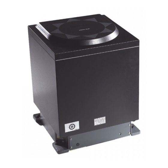
Page 99: Environmental Specifications
TECHNICAL SPECIFICATIONS Environmental Specifications GC80/85 Master compass Enclosure material:.................... Aluminum Color: ..........................Black Temperature range: Operating: ............-10 - 50°C (14 - 122°F) Storage: ............... -25 - 70°C (-13 - 158°F) Angular freedom of gimbal: ........... ±45° for roll and pitch GC80/85 Dual MK2 Control unit Enclosure material:.................... - Page 100 Simrad GC80/85 Dual MK2 Gyro Compass THIS PAGE INTENTIONALLY LEFT BLANK 988-12720-002...
-
Page 101: Drawings
DRAWINGS DRAWINGS This section contains dimensional drawings that show mechanical dimensions of the different GC80/85 units, together with wiring diagrams of the Gyro system. 988-12720-002... -
Page 102: Drawings Included
GC80/85 Remote panel, dimensions D4-710208 Dimensional drawings are available upon request. The following wiring diagrams are enclosed: Name GC80/85 Gyro Compass, Dual system. Wiring diagrams (page 1, 2 and 3). The original signed drawings are recorded at Simrad Egersund. Note! 988-12720-002... - Page 103 DRAWINGS 988-12720-002...
- Page 104 Simrad GC80/85 Dual MK2 Gyro Compass 988-12720-002...
- Page 105 DRAWINGS 988-12720-002...
- Page 106 Simrad GC80/85 Dual MK2 Gyro Compass 988-12720-002...
- Page 107 DRAWINGS 988-12720-002...
- Page 108 Simrad GC80/85 Dual MK2 Gyro Compass 988-12720-002...
- Page 109 DRAWINGS THIS PAGE INTENTIONALLY LEFT BLANK 988-12720-002...
-
Page 110: Spare Part List
Simrad GC80/85 Dual MK2 Gyro Compass SPARE PART LIST This section includes part numbers for all standard and optional units that may be included in a GC80 and GC85 Gyro system. 988-12720-002... -
Page 111: Gc80 Dual Gyro System
SPARE PART LIST 10.1 GC80 Dual Gyro system PART NO DESCRIPTION 27101674 GC80 Master compass 44174027 GC80 Sensitive element 000-15038-001 GC80/85 Dual MK2 Control unit 988-12720-001 GC80/85 Dual MK2 Gyro compass User manual 44174449 Special tool required when installing the Sensitive element 10.2 GC85 Dual Gyro system PART NO... -
Page 112: Gc80/85 Optional Equipment, Dual System
Simrad GC80/85 Dual MK2 Gyro Compass 10.3 GC80/85 Optional equipment, Dual system PART NO DESCRIPTION GC80 Flush mounting kit in Simrad design for remote 27101757 installation of operating panel GC80 Extension cable 5 m for remote installation of Dual 44170769... - Page 113 SPARE PART LIST THIS PAGE INTENTIONALLY LEFT BLANK 988-12720-002...
-
Page 114: Terminal Layout
Simrad GC80/85 Dual MK2 Gyro Compass TERMINAL LAYOUT This section includes tables that list all terminal pins and terminal labelling on the GTERM-A board, the DTERM-A board, the CTERM board, and the BTERM board in the GC80/85 Dual MK2 Control unit. The tables include detailed descriptions of each terminal. -
Page 115: Gterm-A Board
TERMINAL LAYOUT 11.1 GTERM-A board TB1-1 PIN NO NAME DETAILS No.2 Master compass power supply (24 V DC) No.2 Master compass power supply (24 V DC GND) No.2 Master compass inverter alarm (over current) No.2 Master compass inverter alarm (over voltage) No.2 Master compass inverter alarm (GND) No.2 Control unit - Master compass serial signal... - Page 116 Simrad GC80/85 Dual MK2 Gyro Compass TB1-2 PIN NO NAME DETAILS 24M+ Ext. power supply input (no connection) 24M- 9TX+ Serial signal output (IEC61162-1 ed.4/-2 ed.1) 9TX- 9TSC Serial signal GND 9R24- Serial repeater power supply, -24 V DC 9R24+...
- Page 117 TERMINAL LAYOUT TB1-3 PIN NO NAME DETAILS 1RT+ Rate of turn analog signal output 1RT- Rate of turn analog signal GND 2RT+ Rate of turn analog signal output 2RT- Rate of turn analog signal GND 3RT+ Rate of turn analog signal output 3RT- Rate of turn analog signal GND ST51...
-
Page 118: Tb2
Simrad GC80/85 Dual MK2 Gyro Compass TB2-1 PIN NO NAME DETAILS 1TX+ Serial signal output (IEC61162-1 ed.4/-2 ed.1) 1TX- 1TSC Serial signal GND 1R24- Serial repeater power supply, -24 V DC 1R24+ Serial repeater power supply, +24 V DC 2TX+ Serial signal output (IEC61162-1 ed.4/-2 ed.1) - Page 119 TERMINAL LAYOUT TB2-2 PIN NO NAME DETAILS 5TX+ Serial signal output (IEC61162-1 ed.4/-2 ed.1) 5TX- 5TSC Serial signal GND 5R24- Serial repeater power supply, -24 V DC 5R24+ Serial repeater power supply, +24 V DC 6TX+ Serial signal output (IEC61162-1 ed.4/-2 ed.1) 6TX- 6TSC Serial signal GND...
- Page 120 Simrad GC80/85 Dual MK2 Gyro Compass TB2-3 PIN NO NAME DETAILS ST1/OPRX+ ST2/OPRX- ST3/OPSC OPMC+ Not used OPMC- GTX+ GXT- GTSC ST11 ST12 Step signal (open drain signal) ST13 ST14 -24 V DC for step signal output 1 ST15 +24 V DC for step signal output 1...
-
Page 121: Dterm-A Board
TERMINAL LAYOUT 11.2 DTERM-A board TB21A PIN NO NAME DETAILS No. 2 Master compass power supply (24 V DC) No. 2 Master compass power supply (24 V DC GND) No. 2 Master compass inverter alarm (over current) No. 2 Master compass inverter alarm (over voltage) No. -
Page 122: Tb21B
Simrad GC80/85 Dual MK2 Gyro Compass TB21B PIN NO NAME DETAILS 24M+ 24M- 24R+ 24R- 24B+ 24B- Ext. power supply input (no connection) MDCN+ Not used MDCN- G1-1TX+ No. 1 GYRO Serial signal output (IEC61162-1 ed.4/-2 ed.1) G1-1TX- G1-1SC Serial signal GND... -
Page 123: Tb21D
TERMINAL LAYOUT PIN NO NAME DETAILS PRSC TB21D PIN NO NAME DETAILS DFCN1 Heading difference alarm contact output DFCN2 OCACN1 Off course alarm contact output (Not used) OCANC2 MALCN1 Alarm contact for selected Gyro MALCN2 MRNCN1 Running contact for selected Gyro MRNCN2 G1-2TX+ No. -
Page 124: Cterm Board
Simrad GC80/85 Dual MK2 Gyro Compass 11.3 CTERM board TB101 PIN NO NAME DETAILS Input power supply (AC220 V) Input power supply (Battery 24 V DC) Input power supply (Battery GND) Frame Ground TB102 PIN NO NAME DETAILS CTX+ Serial signal output (+) to BAMS (alert) -
Page 125: Bterm Board
TERMINAL LAYOUT 11.4 BTERM board TB105 PIN NO NAME DETAILS CTX+ Serial signal output (+) to BAMS (alert) CTX- Serial signal output (-) to BAMS (alert) CRX+ Serial signal input (+) from BAMS (alert) CRX- Serial signal input (-) from BAMS (alert) Serial signal output (GND) OTX+ Not used... - Page 126 Simrad GC80/85 Dual MK2 Gyro Compass THIS PAGE INTENTIONALLY LEFT BLANK 988-12720-002...
-
Page 127: Dip Switch Settings
DIP SWITCH SETTINGS DIP SWITCH SETTINGS This section includes drawings of the different printed circuits boards in the Control unit that include jumpers and DIP switches. 988-12720-002... -
Page 128: General
Simrad GC80/85 Dual MK2 Gyro Compass 12.1 General 7 different boards in the Dual MK2 Control unit have jumpers and/or DIP switches that are used to configure the GC80/85 system. Only a few of these jumpers/DIP switches are used in installation and pre- running procedures for the Gyro compass. -
Page 129: Gpower Board 1 And 2
DIP SWITCH SETTINGS 12.2 GPOWER board 1 and 2 Jumper settings on GPOWER boards JUMPER DEFAULT FUNCTION DESCRIPTION Over-current value of 24 V DC for Master Open compass is set up. Over-current limit set Short NOTE: Should not be changed! Used for inspection at a factory. -
Page 130: Gterm-A Board
Simrad GC80/85 Dual MK2 Gyro Compass 12.3 GTERM-A board Jumper settings on GTERM-A board JUMPER DEFAULT FUNCTION DESCRIPTION Open = 2 Gyro systems Open Gyro system Short = 1 Gyro system 988-12720-002... -
Page 131: Scc Board 1 And 2
DIP SWITCH SETTINGS 12.4 SCC board 1 and 2 DIP switch settings on SCC boards SWITCH DEFAULT FUNCTION DESCRIPTION S1-1 Power unit OFF = Yes ON = No S1-2 Master compass type OFF = Standard ON = High Speed S1-3 Single or dual system OFF = Single ON = Dual... - Page 132 Simrad GC80/85 Dual MK2 Gyro Compass SWITCH DEFAULT FUNCTION DESCRIPTION OFF = IEC61162-2 ed.1 (NMEA0183, ref. page 3) S1-7 Serial signal format ON = Tokimec OFF = All alarms S1-8 Alarm output setup ON = Only power failures S2-1 For debugging...
-
Page 133: Jumper Settings On Scc Boards
S3-5 “ROT” sentence output OFF = Disabled ON = Enabled OFF = Not used ON = Simrad GC type (80 or 85) shown in For Simrad use S3-6 display at start-up according to S1-2 setting. S3-7 Not used OFF = Gyro running... - Page 134 Simrad GC80/85 Dual MK2 Gyro Compass JUMPER DEFAULT FUNCTION DESCRIPTION Output port: GTERM-A board, "2TX" 1-2 Short = IEC61162-2 ed.1 3-4 Short = IEC61162-1 ed.4 Ref. page 3. Serial signal output 3-4 short setting NOTE: Never use both (2TX) jumpers at the same...
-
Page 135: Scoif Board
DIP SWITCH SETTINGS 12.5 SCOIF board DIP switch settings on SCOIF board SWITCH DEFAULT FUNCTION DESCRIPTION SW1-1 OFF No external sensor SW1-2 OFF S1-1 SW1-1 OFF Not used SW1-2 ON External sensor connection SW1-1 ON External sensor connected SW1-2 OFF S1-2 SW1-1 ON Not used... -
Page 136: Jumper Settings On Scoif Board
Simrad GC80/85 Dual MK2 Gyro Compass Jumper settings on SCOIF board JUMPER DEFAULT FUNCTION DESCRIPTION Output port: GTERM-A board, TB2-1: "3TX" 1-2 short = IEC61162-2 ed.1 or TOKIMEC version 3-4 short (3TX) 3-4 short = IEC61162-1 ed.4 (ref. page 3) - Page 137 DIP SWITCH SETTINGS JUMPER DEFAULT FUNCTION DESCRIPTION Output port: DTERM-A board, TB21C: "G2-1TX" and TB21D: "G2-2TX" 1-2 short = IEC61162-2 or TOKIMEC version Serial signal output 3-4 short 3-4 short = IEC61162-1 ed.4 (ref. setting (G2TX) page 3) NOTE: True heading information on "NO.2 Gyro compass"...
- Page 138 Simrad GC80/85 Dual MK2 Gyro Compass JUMPER DEFAULT FUNCTION DESCRIPTION software is installed while this jumper is short. Short: Internal communication with "NO.2 Gyro compass" Software install or Open: Software is installed in internal communication Short SCC board with "NO.2 Gyro...
- Page 139 DIP SWITCH SETTINGS JUMPER DEFAULT FUNCTION DESCRIPTION Short = Internal communication with External heading sensor Software install or Open = Software is installed in Short internal communication SCOIF board (MWR/EXT) with SCOIF board NOTE: A damage will be given to a circuit if software is installed while this jumper has been short.
- Page 140 Simrad GC80/85 Dual MK2 Gyro Compass JUMPER DEFAULT FUNCTION DESCRIPTION Output port:GTERM-A board, TB2-2: "6TX" 1-2 short = IEC61162-2 or TOKIMEC version 3-4 short (6TX) 3-4 short = IEC61162-1 ed.4 (ref. page 3) NOTE: Never use both jumpers at the same time! Output port:GTERM-A board, TB2-2:...
- Page 141 DIP SWITCH SETTINGS JUMPER DEFAULT FUNCTION DESCRIPTION Output port: DTERM-A board. TB21D: " MALCN" 1-2 short = Normal "CLOSES" Alarm "OPEN" Alarm contact output for 3-4 short Control panel 3-4 short = Normal "OPEN" Alarm (MALCN) (or Change Over panel) "CLOSES"...
- Page 142 Simrad GC80/85 Dual MK2 Gyro Compass JUMPER DEFAULT FUNCTION DESCRIPTION Output port: GTERM-A board. TB2-3: "ST1/OPRX+" 1-2 short = The step signal for "Step signal type repeater" is output (ST1). 3-4 short = Serial signal receive J46* Output port setup for...
-
Page 143: Pcc Board
DIP SWITCH SETTINGS 12.6 PCC board 988-12720-002... -
Page 144: Dip Switch Settings On Pcc Board
Simrad GC80/85 Dual MK2 Gyro Compass DIP switch settings on PCC board SWITCH DEFAULT FUNCTION DESCRIPTION S1-1 HDM function OFF = ON = No S1-2 OCA function OFF = ON = Yes SW1-3 OFF No external sensor connected SW1-4 OFF... -
Page 145: Gpanel-A Board
DIP SWITCH SETTINGS 12.7 GPANEL-A board DIP switch settings on GPANEL-A board SWITCH DEFAULT FUNCTION DESCRIPTION S1-1 For SIMRAD use OFF = ON = For SIMRAD S1-2 S1-3 S1-4 Do not touch S1-5 S1-6 S1-7 S1-8 988-12720-002... - Page 146 Simrad GC80/85 Dual MK2 Gyro Compass THIS PAGE INTENTIONALLY LEFT BLANK 988-12720-002...
-
Page 147: Alarm Messages And Corrective Actions
ALARM MESSAGES AND CORRECTIVE ACTIONS ALARM MESSAGES AND CORRECTIVE ACTIONS This section provides a description of system errors and corrective actions that should be performed by the system operator. 988-12720-002... -
Page 148: The Alarm System
Simrad GC80/85 Dual MK2 Gyro Compass 13.1 The alarm system The GC80/85 system will continually check for faults while the system is running. If a fault occurs, an alarm code will be displayed in the LCD, the Alarm lamp will be flashing, and an audible alarm will be activated. -
Page 149: Master Compass Running Stop Function
ALARM MESSAGES AND CORRECTIVE ACTIONS Master compass running stop function When any abnormal condition or failure (as E-3/E-A is provided or true heading is unstable) occurs in the Master compass, turn the “Master compass power switch” S1 in the control unit to OFF. It is now possible to stop the Master compass from running and change the output of true heading information to a connected external heading sensor. -
Page 150: Complete Alarm Code List
Simrad GC80/85 Dual MK2 Gyro Compass 13.3 Complete alarm code list Alarm Detailed Alarm content Possible cause code code Main power is Main power (AC power source) is lost. abnormal Power supply unit in the control box becomes over current. - Page 151 ALARM MESSAGES AND CORRECTIVE ACTIONS Alarm Detailed Alarm content Possible cause code code MAG/EHS data EHS data abnormal (timeout is 17 sec). abnormal EXT. sensor EXT. sensor system is stopped or serial signal from EXT. communication off sensor is cut (timeout is 15 sec). EXT.
-
Page 152: Alarms Generated By The Dual System
Simrad GC80/85 Dual MK2 Gyro Compass Alarms generated by the Dual system Alarm code Alarm content Possible cause Main power is Main Power Fail Main power from GYRO 1 or GYRO 2 is lost. abnormal Heading difference between GYRO 1 and GYRO 2 true HDG. -
Page 153: Bams Complete Alarm Code List
ALARM MESSAGES AND CORRECTIVE ACTIONS BAMS complete alarm code list Alarm code to Alarm meet BAMS Name Priority Category Remarks code specification 10300 MAIN PWR FAIL 10301 24R PWR FAIL 10302 INVERTER FAIL 10303 CONT. PWR FAIL 10304 ROTOR FAIL 10305 LEVEL FAIL 10320... -
Page 154: Alarm Priority List
Simrad GC80/85 Dual MK2 Gyro Compass Alarm Priority list Alarm priority Description Indication Buzzer sound Alarm requires immediate attention and action. 3 short beeps. Repeated High (The operator should switch to every 7 seconds until the (Alarm) manual steering because the ACK button is pressed.
Need help?
Do you have a question about the GC80 Dual MK2 and is the answer not in the manual?
Questions and answers