Table of Contents
Advertisement
Quick Links
Advertisement
Table of Contents

Related Manuals for Simrad GC80 Compact MK2


Summary of Contents for Simrad GC80 Compact MK2
- Page 1 GC80/85 Compact MK2 User Manual ENGLISH www.navico-commercial.com...
- Page 2 PREFACE Document history Rev. 001 First issue. Added trademark section, disclaimer, and copyright section. Rev. 002 Added section about Master compass power switch. Rev. 003 Updates to BAM conn. ext. cables, alarm code list, notes added. 988-12718-003...
- Page 3 Simrad GC80/85 Compact MK2 Gyro Compass THIS PAGE INTENTIONALLY LEFT BLANK...
-
Page 4: Preface
Translation of the Documentation, the English language version of the Documentation will be the official version of the Documentation. Copyright Copyright © 2021 Navico Holding AS. Trademarks Navico is a registered trademark of Navico Holding AS. ® Simrad is used by license from Kongsberg. ® 988-12718-003... -
Page 5: About This Manual
Intended audience This manual is intended as a reference guide for installing, operating and maintaining the Simrad GC80/85 Expanded MK2 Gyro compass. The manual assumes that the operator is a qualified ship officer, or is under supervision of a qualified person. - Page 6 An overview of the GC80/85 Compact Gyro system and its components. 3. User interface An overview of the GC80 Compact MK2 Control unit and the user interface. 4. Operation Main operating procedures for using the GC80/85 Compact MK2 Gyro compasses.
-
Page 7: Table Of Contents
Precautions in use ............12 System components............13 Bearing repeaters ............13 USER INTERFACE......................16 GC80 Compact MK2 Control unit ........16 OPERATION ........................ 19 System start-up and shut-down ......... 19 Start-up..............19 Turning the Gyro compass OFF ........20 Selecting active compass .......... - Page 8 CONTENTS BAMS ............... 31 MAINTENANCE......................33 General................33 Precautions ..............33 Cleaning the operator panels and the cabinet surface .... 33 Checking the connectors ........... 33 Checking mechanical installation ........33 Preventive maintenance intervals ........34 Replacing the Sensitive element ......... 34 Mechanical installation ..........
- Page 9 Input specifications ............77 Output Specifications ............79 Physical dimensions ............81 GC80 Master compass ..........81 GC80 Compact MK2 Control unit ........81 GC80 Power supply unit (option)........81 Power ................81 GC80/85 Master compass ..........81 GC80 Compact MK2 Control unit ........81 GC80 Power supply unit (option)........
- Page 10 CONTENTS TERMINAL LAYOUT ....................95 11.1 ICNT board ..............95 TB1 ................95 TB2 ................98 TB3 ................99 DIP SWITCH SETTINGS .................... 101 12.1 Compact MK2 Control unit ..........101 ICNT board ............. 102 GPANEL-A board ............105 ALARM MESSAGES AND CORRECTIVE ACTIONS ........... 110 13.1 The alarm system ............
- Page 11 SYSTEM OVERVIEW THIS PAGE INTENTIONALLY LEFT BLANK 988-12718-003...
-
Page 12: System Overview
GC80 and GC85 Compact Gyro systems have different Sensitive elements, but use the same GC80 Compact MK2 Control unit. The systems are identified by divergent DIP switch settings in Master compass and in the Control unit. -
Page 13: System Components
MAINTENANCE page 33 onwards. If any unusual behavior is observed during daily inspections, the cause should be found and corrected. If necessary, the local Simrad dealer should be contacted. If any alarm is generated, verify the reason for the alarm. System components... - Page 14 Simrad GC80/85 Compact MK2 Gyro Compass A proprietary Tokimec serial signal may also be available, but this is Note! normally not used. These signals may be set separately for each circuit. For connection of repeaters, refer to the wiring diagrams from page 84 onwards.
- Page 15 SYSTEM OVERVIEW THIS PAGE INTENTIONALLY LEFT BLANK 988-12718-003...
-
Page 16: User Interface
Simrad GC80/85 Compact MK2 Gyro Compass USER INTERFACE This section gives an overview of the GC80 Compact MK2 Control unit and the user interface. GC80 Compact MK2 Control unit The Control unit includes the Control panel for the Gyro compass. - Page 17 USER INTERFACE is active. Selecting active compass Refer page 21. DISP button Displaying present settings Used to display data on the LCD. Refer page DISP SET button System start-up and Used to change data and input sources. Refer software configuration page 61 onwards.
- Page 18 Simrad GC80/85 Compact MK2 Gyro Compass THIS PAGE INTENTIONALLY LEFT BLANK 988-12718-003...
-
Page 19: Operation
OPERATION OPERATION This section describes the main operating procedures used when operating the GC80/85 Compact MK2 Gyro compasses. System start-up and shut-down A GC80/85 Compact Gyro system is usually left with power on. If the system has to be shut down and restarted, follow the procedures described in the following sections. -
Page 20: Turning The Gyro Compass Off
Simrad GC80/85 Compact MK2 Gyro Compass The indicated start bearing is accepted by pressing the ACK/ENT button, or increased/decreased by using the ARROW buttons and GYRO then pressing the ACK/ENT button. If no action is taken within 3 minutes, the start-up process will continue with the indicated start bearing. -
Page 21: Selecting Active Compass
OPERATION Selecting active compass If an external heading sensor is connected to the GC80/85, it is possible to toggle between Gyro and external heading sensor as active steering sensor. The Gyro system will normally be used with the Gyro compass selected as active compass. -
Page 22: Displaying Present Settings
Simrad GC80/85 Compact MK2 Gyro Compass Displaying present settings When pressing the DISP button on the GC80 Control unit, the system will loop through a display sequence showing present settings for the system. The sequence will depend on whether an external compass is connected or not. - Page 23 OPERATION Display state Display Description - Error codes (up to 4) DISP - Error indication press on DISP button DISP GYRO - True output bearing press on - Active compass DISP button Normal operation 988-12718-003...
-
Page 24: Displaying Settings With External Sensor Connected
Simrad GC80/85 Compact MK2 Gyro Compass Displaying settings with external sensor connected Display state Display Description GYRO - True output bearing - Active compass Normal operation The compass indication equals the sensor GYRO selected as active compass (Gyro or external) -
Page 25: Confirming Present Settings
OPERATION Display state Display Description GYRO - True output bearing DISP - Active compass press on DISP button Normal operation GYRO Confirming present settings System start-up and After the GC80 is configured according to the software configuration described on page 61 onwards, it should not be necessary to adjust any settings when operating the Gyro compass. -
Page 26: Speed
Simrad GC80/85 Compact MK2 Gyro Compass when the vessel is in harbor. If there is any significant difference between the displayed value and the vessel’s actual latitude, the Setting the Latitude value should be adjusted according to input source , page 63. - Page 27 OPERATION When the course is within 270° - 0° - 90°, true heading is found by Note! subtracting the speed error from the compass heading. If the course is within 90° - 180° - 270°, true heading is found by adding the speed error to the compass heading.
- Page 28 Simrad GC80/85 Compact MK2 Gyro Compass VESSEL HEADING (degrees) 20 10 LATITUDE (degrees) 988-12718-003...
-
Page 29: Pendulum Function
OPERATION Pendulum function GC80/85 software includes a pendulum function that enables the heading to be changed by 180°. The heading change is activated by closing a potential free contact connected between TB1-2, pin 25 and 26 in the GC80/85 Control unit. To enable the function, S2-4 on the ICNT board has to be set to ON. -
Page 30: Alarm Messages
Simrad GC80/85 Compact MK2 Gyro Compass Alarm messages The GC80/85 system will continually check for faults while the system is running. If a fault occurs, an alarm code will be displayed in the LCD, the Alarm lamp will be flashing, and an audible alarm will be activated. -
Page 31: Acknowledging An Alarm
OPERATION Acknowledging an alarm An alarm is acknowledged by pressing the ACK/ENT button. The audible alarm will be silenced. If the alarm situation has disappeared, the alarm lamp will be switched off and the alarm code will be removed from the LCD. If the alarm situation continues, the alarm lamp will switch from flashing to steady light. - Page 32 Simrad GC80/85 Compact MK2 Gyro Compass THIS PAGE INTENTIONALLY LEFT BLANK 988-12718-003...
-
Page 33: Maintenance
However, a limited amount of preventive maintenance should be performed to verify safe operation and durability. If any strange motion, smell, sound or heat is generated from any unit, please contact a Simrad dealer. Precautions Touching internal parts may cause electric shock if power is connected to the system, even if the POWER button is turned OFF. -
Page 34: Preventive Maintenance Intervals
(can operate with backup) we recommend 6-8 years or when it fails. Replacing the Sensitive element The Sensitive element should only be replaced by authorized Simrad Caution personnel. A special tool is required when installing the Sensitive element. This tool is Note! optional and must be ordered from Simrad (part no. - Page 35 OPERATION Loosen the screw on the plug-holder on the Sensitive element, and disconnect the plug. Remove the 4 screws securing the Sensitive element. Tilt the Horizontal ring to the side where the plug is located, and carefully remove the element from the compass. Place the defective Sensitive element in its original package, and put the rubber tube on top of the element.
- Page 36 Simrad GC80/85 Compact MK2 Gyro Compass Tilt the Horizontal ring to the side where the plug is located, and carefully put the Sensitive element into the ring. The socket on the Sensitive element should be located right above the plug attached to the Horizontal ring.
- Page 37 OPERATION ASSEMBLY JIG WITH 1 CIRCLE ASSEMBLY JIG WITH 2 CIRCLES Replace the assembly jigs with the 2 remaining screws after placing the ground wire as shown in the figure. Loosen the screw on the plug holder on the Sensitive element, and lift the holder 2-3 mm upwards.
-
Page 38: Verifying The Element's Tilt Angle
Simrad GC80/85 Compact MK2 Gyro Compass Verifying the element’s tilt angle Tilt the Sensitive element by hand towards the reference level tool on the Horizontal ring and keep it tilted for approximately 1 minute. Remove the pressure and observe that the tilt angle remains at: GC80: 15°... -
Page 39: Parameter Updates
OPERATION If the tilt angle is incorrect, weight disks must be adjusted by moving weights from one side to the other. After adjustments, wait for 2 minutes for the oil to set before the tilt angle verification is repeated. Caution The Sensitive element must have equal number of weight disks on both weight points on the tilting side (north and south sides)! Carefully rotate the Horizontal ring at least 1 complete rotation. -
Page 40: Balancing The Horizontal Ring
Simrad GC80/85 Compact MK2 Gyro Compass Balancing the Horizontal ring After the Sensitive element has been replaced, the Gyro compass should be turned ON as described on page 19. When the compass has been running continuously for at least 2 hours, the Horizontal ring should be adjusted. -
Page 41: Adjusting The Rotor Balance
OPERATION Adjusting the Rotor balance After replacing a Sensitive element, it is very important to verify the rotor balance. If necessary, adjust the rotor balance. On the Sensitive element, the reference level tool is mounted on the opposite side of the blue plug. When the compass has been running continuously for at least 3 hours, the balancing process can start. -
Page 42: Replacing The Fuses
Simrad GC80/85 Compact MK2 Gyro Compass Replacing the fuses WARNING Before a fuse is replaced, disconnect the respective power for the damaged fuse. Use the procedures described on the following pages when replacing the fuses. Master compass Fuse F1 is located inside the fuse holder in the front of the Master compass. - Page 43 OPERATION WARNING Make sure that power is disconnected from pin 1-8 on TB3 before any fuse is replaced! The fuses in the Compact MK2 Control unit are open glass type and may be Note! damaged if handled with force. Push down and rotate the fuse holder top CCW. Remove damaged fuse.
-
Page 44: Power Supply Unit (Option)
Simrad GC80/85 Compact MK2 Gyro Compass Power supply unit (option) FUSE NO CAPACITY TB-NO SIGNAL DESCRIPTION F201 6.3A TB201 2AC1/2 Main power supply F202 TB201 2B+/- Emergency power supply F201 F202 F201 (6.3 A) – TB201 F202 (20 A) WARNING Make sure that power is disconnected from TB201 before any fuses are replaced. - Page 45 Simrad GC80/85 Compact MK2 Gyro Compass THIS PAGE INTENTIONALLY LEFT BLANK 988-12718-003...
-
Page 46: Installation
Simrad GC80/85 Compact MK2 Gyro Compass INSTALLATION This section is a reference guide to correctly install and configure the GC80/85 Gyro compasses. Unpacking and handling A GC80/85 Gyro compass consists of the following units: - Master compass - Sensitive element... -
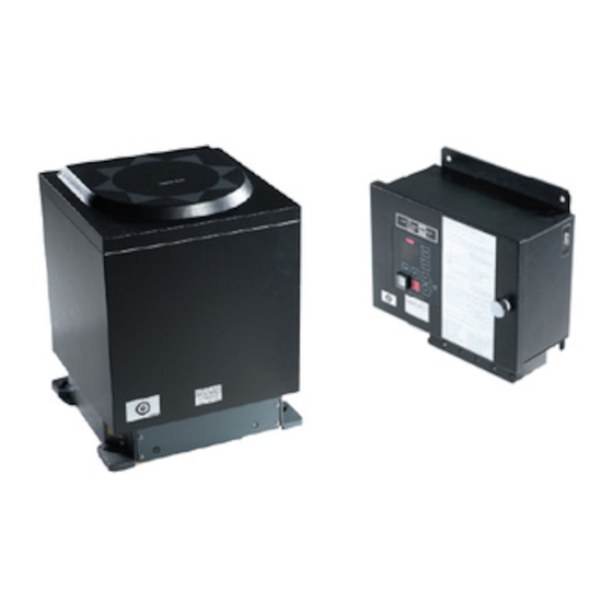
Page 47: Control Unit
Simrad GC80/85 Compact MK2 Gyro Compass Control unit The Control unit is bulkhead mounted using 4 bolts as shown in the illustration. Flush mounting the Control panel The Control panel may be removed from the Control unit and mounted in a remote location using the optional flush mounting kit (part number 27101757). - Page 48 Simrad GC80/85 Compact MK2 Gyro Compass Disconnect the cable’s grounding wires (labelled FG) from the Control panel and from the ICNT board. Disconnect the plugs and remove the Control panel’s cable(s). Loosen the 4 nuts holding the Control panel and remove the panel.
-
Page 49: Power Supply Unit (Option)
Simrad GC80/85 Compact MK2 Gyro Compass Power supply unit (option) Refer mounting description of the Control unit above. Dimensional drawings for the optional Power supply unit are found on page 87. Jumper settings in Compact MK2 Control unit When the optional Power supply unit is included in the GC80/85 Compact Gyro system, the GC80/85 Control unit’s jumper settings have to be... -
Page 50: Master Compass
Simrad GC80/85 Compact MK2 Gyro Compass Master compass Select a mounting location where the deck is horizontal, flat and with little vibration, and where the pitch/roll motion is minimal. It is also important to select a mounting location with sufficient space for installation and service. -
Page 51: Cabling
Simrad GC80/85 Compact MK2 Gyro Compass The foam rubber should be kept for re-use if the Master compass has to be Note! sent to factory for service! Cabling No cables are included when the Gyro system is delivered from factory. -
Page 52: Activating The Gc80 Or Gc85 Control Unit
Simrad GC80/85 Compact MK2 Gyro Compass Activating the GC80 or GC85 Control unit When the Gyro system is shipped from factory, all DIP switches in the Control unit are set as a standard GC80 system. Before the system is started, the switch settings described below have to be changed to match a GC85 system. -
Page 53: Activating An External Heading Sensor
Simrad GC80/85 Compact MK2 Gyro Compass Activating an external heading sensor If an external heading sensor is connected to the GC80/85 system, DIP switch no.5 on S1 on the ICNT board has to be set to enable the external heading sensor. -
Page 54: Hdt/Ths
Simrad GC80/85 Compact MK2 Gyro Compass HDT/THS Selecting HDT/THS heading output data from the Gyro The serial data output can be set as HDT or THS using DIP switch S4-5 on the ICNT board. THS is disabled = HDT output... -
Page 55: Activating The Pendulum Function
Simrad GC80/85 Compact MK2 Gyro Compass Activating the pendulum function If an external switch is connected to GC80/85 to operate the pendulum function, DIP switch no.4 on S2 on the ICNT board has to be set to activate the pendulum function. -
Page 56: Activating External/Internal Reset Of External/Internal Buzzer Alarm
Simrad GC80/85 Compact MK2 Gyro Compass Activating external/internal reset of external/internal buzzer alarm In some installations, it is required to have the Gyro system connected to an external alarm panel (central bridge alarm panel). To be able to have the right handshake available from GC80/85 systems some DIP switches must be set. -
Page 57: Installing The Sensitive Element
Simrad GC80/85 Compact MK2 Gyro Compass Installing the Sensitive element The Sensitive element is shipped from the factory in a separate package. The element has to be installed in the Master compass according to the description below. A special tool (part no. 44174449) is required when installing the Sensitive Note! element. - Page 58 Simrad GC80/85 Compact MK2 Gyro Compass ASSEMBLY JIG WITH 1 CIRCLE ASSEMBLY JIG WITH 2 CIRCLES Replace the assembly jigs with the 2 remaining screws. Locate the ground wire on 1 of the screws as shown in the figure. Loosen the screw on the plug holder on the Sensitive element and lift the holder 2-3 mm upwards.
-
Page 59: Verifying The Element's Tilt Angle
Simrad GC80/85 Compact MK2 Gyro Compass Verifying the element’s tilt angle Tilt the Sensitive element by hand towards the reference level tool on the Horizontal ring and keep it tilted for approximately 1 minute. Remove the pressure and observe that the tilt angle remains at: GC80: 15°... - Page 60 Simrad GC80/85 Compact MK2 Gyro Compass If the tilt angle is incorrect, weight disks must be adjusted by moving weights from one side to the other. After adjustments, wait for 2 minutes for the oil to set before the tilt angle verification is repeated.
-
Page 61: System Start-Up And Software Configuration
Simrad GC80/85 Compact MK2 Gyro Compass System start-up and software configuration When all GC80 units are installed and the cables connected according to the procedures described in previous chapters, the system is ready for the first time start-up procedure. System start-up Turn ON the Gyro system by pressing the POWER button on the Control panel. -
Page 62: Configuring The Gyro System
Simrad GC80/85 Compact MK2 Gyro Compass The indicated start bearing is accepted by pressing the ACK/ENT button, or increased/decreased by using the ARROW buttons and then GYRO pressing the ACK/ENT button. If no action is taken within 3 minutes, the start-up process will continue with the indicated start bearing. -
Page 63: Setting The Latitude Input Source
Simrad GC80/85 Compact MK2 Gyro Compass Press the DISP button again to select sub-category 1.2.F, and use the ARROW buttons to increase or decrease the parameter value until the value corresponds with the parameter for the new Sensitive element. Confirm the entry by pressing the ACK/ENT button. -
Page 64: Setting The Speed Input Source
Simrad GC80/85 Compact MK2 Gyro Compass - If Gyro is selected, the display will change to flashing numbers - If GPS is selected, the display will show the latitude value read from the GPS When Gyro is selected and the numbers are flashing, press the ARROW buttons to increase/decrease the latitude value and confirm the entry with the ACK/ENT button. -
Page 65: Balancing The Horizontal Ring
Simrad GC80/85 Compact MK2 Gyro Compass LOG (serial) Select active speed input source and confirm the selection by pressing the ACK/ENT button. If Manual input source is selected, the display will change to show flashing numerical values. Use the ARROW buttons to enter the speed value, and confirm the input by pressing the ACK/ENT button. -
Page 66: Adjusting True Heading
Simrad GC80/85 Compact MK2 Gyro Compass Adjusting True heading After the GC80/85 is settled, the Gyro compass has to be calibrated against an external reference, e.g.: - a known target - astronomical observation - the heading of the pier or quay the vessel is moored to... - Page 67 Simrad GC80/85 Compact MK2 Gyro Compass THIS PAGE INTENTIONALLY LEFT BLANK 988-12718-003...
-
Page 68: Advanced Settings
Simrad GC80/85 Compact MK2 Gyro Compass ADVANCED SETTINGS This section gives an overview of the Extension menu: how to enter the menu and how to change parameter values. General The Extension menu holds internal parameters and communication parameters required to achieve the best possible heading accuracy on the GC80/85 Gyro compass. - Page 69 Simrad GC80/85 Compact MK2 Gyro Compass Exit the Extension menu by pressing and holding the SET and ACK/ENT buttons simultaneously for at least 3 seconds. MAIN MENU CHANGE / CLEAR PARA- METER VALUE DISP DISP DISP DISP NEXT MAIN NEXT SUB...
-
Page 70: The Extension Menu Overview
Simrad GC80/85 Compact MK2 Gyro Compass The Extension menu overview Main Default Parameter/description Range category category value 1.1.U Damping gain 1.00 0.00 – 2.00 Determines the damping (damping operation in north-seeking motion = half cycle attenuation) and represents a coefficient (ratio) to the standard value stored in the software. - Page 71 Simrad GC80/85 Compact MK2 Gyro Compass Main Default Parameter/description Range category category value 1.7.G X signal pickup gain (v/°) 2.32 0.00 – 5.00 Distance of the Sensitive element share and the rotor axis direction. Inclination angle around horizontal axis is obtained equivalently by monitoring this signal. For...
- Page 72 Simrad GC80/85 Compact MK2 Gyro Compass Main Default Parameter/description Range category category value 2.1.o Bearing offset A (°) 0.0 – 359.9 Offset value included in the “master bearing” and used for correction of fixed error (°). If the Master compass cannot be mounted parallel to the vessel’s fore-after line, this parameter is used to compensate for a small mounting error.
- Page 73 Simrad GC80/85 Compact MK2 Gyro Compass Main Default Parameter/description Range category category value 2.9.G Display/setting of GPS connection bE or Non The following abbreviations are used: GPS connected Non: No GPS connected NOTE: When this value is set to “Non”, GPS cannot be selected as the vessel’s input for speed...
- Page 74 Simrad GC80/85 Compact MK2 Gyro Compass Main Default Parameter/description Range category category value 3.1.E Alarm (error) 3.2.n Occurred number of zero-cross errors 3.3.H Maximum zero-cross errors 3.4.y Occurred year of zero-cross errors 3.5.N Occurred month/day of zero-cross errors 3.6.t Occurred hour/minute of zero-cross errors 3.7.n...
- Page 75 Simrad GC80/85 Compact MK2 Gyro Compass THIS PAGE INTENTIONALLY LEFT BLANK 988-12718-003...
-
Page 76: Technical Specifications
Simrad GC80/85 Compact MK2 Gyro Compass TECHNICAL SPECIFICATIONS This section lists all specifications for the GC80/85 Gyro compasses. Accuracy Settling time: ..................within 3 hours (If startup heading is within +/-5° of actual heading) Settle point error: .................. less than ±0.3º... -
Page 77: Input Specifications
TECHNICAL SPECIFICATIONS Pendulum function ................refer page 29 Input specifications Serial input signal (GPS) Circuits: ....................1 Electrical: ..............RS422/NMEA0183 Baud rate: ................4800 bps Data bits: ..................8 bits Parity: ....................None Stop bits: ....................1 Transmit freq.: ................1 – 5 Hz Input format: $--GGA,x,xx.x,N,xx.x,E,x,~*hh<CR><LF>... - Page 78 Simrad GC80/85 Compact MK2 Gyro Compass Input format: $--VBW,x.x,x.x,A~*hh<CR><LF> INS (BAMS) Circuits: ....................1 Electrical: ..............RS422/NMEA0183 Baud rate: ................4800 bps Data bits: ..................8 bits Parity: ....................None Stop bits: ....................1 Transmit freq.: ............. INDETERMINATELY Input format: $--ACN,xxxxxx.xx,aaa,x.x,x.x,a,C*hh<CR><LF>...
-
Page 79: Output Specifications
TECHNICAL SPECIFICATIONS Output Specifications Serial output signal 1 Circuits: ....................4 Electrical: ................RS422/485 When Gyro is Baud rate: selected GC80:..............4800/38400 bps GC85:................38400 bps Baud Rate for GC85, refer Jumper settings on ICNT board, output serial Note! signal selection, page 106. Data bits: .................. - Page 80 Simrad GC80/85 Compact MK2 Gyro Compass Data no.4 $--ROT,-xxx.x,a*hh<CR><LF> Data no.5 $--PTKM,--ALM,xxxx,x,xx*hh<CR><LF> INS (BAMS) Circuits: ....................1 Electrical: ..............RS422/NMEA0183 Baud rate: ................4800 bps Data bits: ..................8 bits Parity: ....................None Stop bits: ....................1 Transmit freq.: Data no.1, 4: ................30 s Data no.2, 3: ..........
-
Page 81: Physical Dimensions
Height:..................... 438 mm (17.2”) Width: ...................... 340 mm (13.4”) Depth:......................340 mm (13.4”) Weight: ....................... 23 kg (51 lbs) GC80 Compact MK2 Control unit Height:....................... 252 mm (9.9”) Width: ...................... 278 mm (10.9”) Depth:......................126 mm (5.0”) Weight ......................7 kg (15 lbs) GC80 Power supply unit (option) Height:..................... -
Page 82: Environmental Specifications
Simrad GC80/85 Compact MK2 Gyro Compass Environmental specifications GC80/85 Master compass Enclosure material: ..................Aluminum Color: .......................... Black Temperature range: Operating: ............-10 - 50°C (14 - 122°F) Storage: ............-25 – 70°C (-13 – 158°F) Angular freedom of gimbal: ..........±45° for roll and pitch GC80 Compact MK2 Control unit Enclosure material: .................. - Page 83 DRAWINGS THIS PAGE INTENTIONALLY LEFT BLANK 988-12718-003...
-
Page 84: Drawings
Dimensional drawings are available upon request. The following wiring diagrams are enclosed: Name GC80/85 Gyro Compasses, Compact system. Wiring diagram GC80/85 Gyro Compasses, Compact system with Power supply unit. Wiring diagram The original signed drawings are recorded at Simrad Egersund. Note! 988-12718-003... - Page 85 DRAWINGS 988-12718-003...
- Page 86 Simrad GC80/85 Compact MK2 Gyro Compass 988-12718-003...
- Page 87 DRAWINGS 988-12718-003...
- Page 88 Simrad GC80/85 Compact MK2 Gyro Compass 988-12718-003...
- Page 89 DRAWINGS 988-12718-003...
- Page 90 Simrad GC80/85 Compact MK2 Gyro Compass 988-12718-003...
- Page 91 PART LIST THIS PAGE INTENTIONALLY LEFT BLANK 988-12718-003...
-
Page 92: Part List
Simrad GC80/85 Compact MK2 Gyro Compass PART LIST This section includes part numbers for all standard and optional units that may be included in a GC80 and GC85 Gyro system. 10.1 GC80 Compact Gyro system PART NO DESCRIPTION 27101674 GC80 Master compass... -
Page 93: Gc80/85 Optional Equipment, Compact System
GC80/85 Optional equipment, Compact system PART NO DESCRIPTION 27101724 GC80/85 Power supply unit GC80 Flush mounting kit in Simrad design for remote 27101757 installation of operating panel GC80 Extension cable 5 m for remote installation of operating 44170736 panel normally mounted in Control unit... - Page 94 Simrad GC80/85 Compact MK2 Gyro Compass THIS PAGE INTENTIONALLY LEFT BLANK 988-12718-003...
-
Page 95: Terminal Layout
TERMINAL LAYOUT TERMINAL LAYOUT This section includes tables that list all terminal pins and terminal labelling on PCBs in the GC80 Control unit. The tables include detailed descriptions of each terminal. 11.1 ICNT board TB1-1 PIN NO NAME DETAILS Master compass power supply (24 V DC) Master compass power supply (24 V DC GND) Master compass inverter alarm (over current) Master compass inverter alarm (over voltage) - Page 96 Simrad GC80/85 Compact MK2 Gyro Compass TB1-2 PIN NO NAME DETAILS BZSP+ Pendulum/Remote buzzer stop signal input BZSP- EACK+ External alarm acknowledge signal input EACK- 1TX+ Serial signal output (+) 1TX- Serial signal output (-) 1TSC Serial signal output (GND)
- Page 97 TERMINAL LAYOUT TB1-3 PIN NO NAME DETAILS GRX+ GPS serial signal input GRX- Serial signal input (GND) LRX+ Speed Log serial signal input LRX- Serial signal input (GND) ESRX+ External sensor serial signal input ESRX- External sensor serial signal GND Input dry contact of Speed Log 200/400 p.p.n.m.
-
Page 98: Tb2
Simrad GC80/85 Compact MK2 Gyro Compass PIN NO NAME DETAILS CTX+ Serial signal output (+) to BAMS (alert) CTX- Serial signal output (-) to BAMS (alert) CRX+ Serial signal input (+) from BAMS (alert) CRX- Serial signal input (-) from BAMS (alert) -
Page 99: Tb3
Input power supply (main 24 V DC) 24M- Input power supply (main GND) 24R+ 24R- Normally not used (Only when connecting a Simrad Power supply unit) 24B+ 24B- 24BT+ Input power supply (Battery 24 V DC) 24BT- Input power supply (Battery GND) - Page 100 Simrad GC80/85 Compact MK2 Gyro Compass THIS PAGE INTENTIONALLY LEFT BLANK 988-12718-003...
-
Page 101: Dip Switch Settings
DIP SWITCH SETTINGS DIP SWITCH SETTINGS This section includes drawings of the different printed circuits boards in the Control unit that include jumpers and DIP switches. 12.1 Compact MK2 Control unit 1 board in the Compact MK2 Control unit has jumpers and/or DIP switches that may be used to configure the GC80/85 system. -
Page 102: Icnt Board
Simrad GC80/85 Compact MK2 Gyro Compass ICNT board Default settings 988-12718-003... - Page 103 DIP SWITCH SETTINGS DIP switch settings on ICNT board SWITCH DEFAULT FUNCTION DESCRIPTION S1-1 Power unit OFF = Yes ON = No S1-2 Master compass type OFF = Standard ON = High Speed S1-3 Control unit type OFF = Type S ON = Type D (Dual) S1-4 2 Gyros used...
- Page 104 Ban or permission of a selection. S3-5 “ROT” sentence output OFF = Disabled ON = Enabled OFF = Not used ON = Simrad GC type (80 or 85) shown in S3-6 For Simrad use display at start-up according to S1-2 setting. S3-7 Not used...
-
Page 105: Gpanel-A Board
DIP SWITCH SETTINGS GPANEL-A board DIP switch settings on GPANEL-A board SWITCH DEFAULT FUNCTION DESCRIPTION S10-1 For Simrad use OFF = No ON = for Simrad S10-2 S10-3 S10-4 Do not touch S10-5 S10-6 S10-7 S10-8 988-12718-003... - Page 106 Simrad GC80/85 Compact MK2 Gyro Compass Jumper settings on ICNT board JUMPER DEFAULT FUNCTION DESCRIPTION Used when resetting the CPU Open CPU reset (RESET) Output port: “1TX” 3-4 short = IEC61162-2 ed.1 or TOKIMEC version 5-6 short = IEC61162-1 ed.4 5-6 short (ref.
- Page 107 DIP SWITCH SETTINGS JUMPER DEFAULT FUNCTION DESCRIPTION Output port: “3TX” 1-2 short = IEC61162-2 ed.1 or TOKIMEC version 3-4 short = IEC61162-1 ed.4 3-4 short (ref. page 13) (3TX) NOTE: Never use both jumpers at the same time! Output port: “4TX” 1-2 short = IEC61162-2 ed.1 or TOKIMEC version 3-4 short = IEC61162-1 ed.4 3-4 short...
- Page 108 Simrad GC80/85 Compact MK2 Gyro Compass JUMPER DEFAULT FUNCTION DESCRIPTION Input port: “SL” 1-2 short = 200 p.p.n.m. 1-2 short LOG pulse selection 3-4 short = 400 p.p.n.m. (LOG) NOTE: Never use both jumpers at the same time! Output port: “ALCN”...
- Page 109 ALARM MESSAGES AND CORRECTIVE ACTIONS THIS PAGE INTENTIONALLY LEFT BLANK 988-12718-003...
-
Page 110: Alarm Messages And Corrective Actions
Simrad GC80/85 Compact MK2 Gyro Compass ALARM MESSAGES AND CORRECTIVE ACTIONS This section provides a description of system errors and corrective actions that should be performed by the system operator. 13.1 The alarm system The GC80/85 compass will continually check for faults while the system is running. -
Page 111: Acknowledging An Alarm
The following pages present an overview of symptoms and corrective actions for errors that may be corrected by the operator. If none of these procedures correct the problem, contact the local Simrad dealer for advice or to request on-board service. -
Page 112: Internal Power Failure In Control Unit
If no alarm is activated, continue the start-up procedure as Start-up described in , page 19. If the alarm continues, contact Simrad’s local dealer for assistance. Inverter malfunction The alarm is generated if the Inverter in the Master compass is over current or over voltage. -
Page 113: System Communication Failure
ALARM MESSAGES AND CORRECTIVE ACTIONS If the bearing input is accepted by the system, the LCD will display current bearing without flashing. Report the error to Simrad even if the bearing is accepted and the alarm removed. System communication failure Alarms generated when there is a malfunction in the communication from the Master compass to the Control unit. -
Page 114: Internal Communication Error
Simrad GC80/85 Compact MK2 Gyro Compass Internal communication error Generated when the communication from the external bearing sensor has stopped ( ), or when an error is detected in the communication ( ). Caution When these alarms are generated, the bearing information from the external bearing sensor may have large error. -
Page 115: Failure When Powering On The Gyro Compass
ALARM MESSAGES AND CORRECTIVE ACTIONS Serial repeater: XF1 to XF4: 1 A For location and replacement of the fuses, refer to page 42 onwards. No output on any repeater Disconnect the power from the Control unit, and check the following fuse: XF8: 10 A For location and replacement of the fuses, refer to page 42 onwards. -
Page 116: Complete Alarm Code List
Simrad GC80/85 Compact MK2 Gyro Compass 13.4 Complete alarm code list Alarm Detailed Alarm content Possible cause code code Main power is When the main power (AC power source) is lost. abnormal Power supply unit in the control box becomes over current. - Page 117 ALARM MESSAGES AND CORRECTIVE ACTIONS Alarm Detailed Alarm content Possible cause code code MAG/EHS MAG/EHS system is stopped or serial signal from GPS is cut communication off (Timeout is 15 sec.). MAG/EHS data EHS data abnormal (Timeout is 17 sec.). abnormal EXT.
-
Page 118: Bams Complete Alarm Code List
Simrad GC80/85 Compact MK2 Gyro Compass BAMS complete alarm code list Alarm code to Alarm meet BAMS Name Priority Category Remarks code specification 10300 MAIN PWR FAIL 10301 24R PWR FAIL 10302 INVERTER FAIL 10303 CONT. PWR FAIL 10304 ROTOR FAIL... - Page 119 ALARM MESSAGES AND CORRECTIVE ACTIONS Alarm Priority list Alarm priority Description Indication Buzzer sound Alarm requires immediate attention and action. 3 short beeps. Repeated High (The operator should switch to every 7 seconds until the (Alarm) ACK button is pressed. manual steering because the automatic steering may be unavailable).
Need help?
Do you have a question about the GC80 Compact MK2 and is the answer not in the manual?
Questions and answers