Table of Contents
Advertisement
Quick Links
Advertisement
Table of Contents

Subscribe to Our Youtube Channel
Related Manuals for AXIOMTEK tBOX520-ADL-MR Series


Summary of Contents for AXIOMTEK tBOX520-ADL-MR Series
- Page 1 tBOX520-ADL-MR Series Embedded Systems User’s Manual...
- Page 2 Disclaimers This manual has been carefully checked and believed to contain accurate information. Axiomtek Co., Ltd. assumes no responsibility for any infringements of patents or rights of any third party, and any liability arising from such use. Axiomtek does not warrant or assume any legal liability or responsibility for the accuracy, completeness or usefulness of any information in this document.
-
Page 3: Safety Precautions
Safety Precautions Before getting started, please read the following important safety precautions. User should not modify any unmentioned jumper setting without Axiomtek FAE’s instruction. Any modification without instructions might damage the system. The tBOX520-ADL-MR does not come equipped with an operating system. An operating system must be loaded first before installing any software into the computer. -
Page 4: Classification
Classification Degree of production against electric shock: not classified Degree of protection against the ingress of water: IP30 Equipment not suitable for use in the presence of a flammable anesthetic mixture with air or with oxygen or nitrous oxide. Mode of operation: Continuous General Cleaning Tips You may need the following precautions before you begin to clean the computer. - Page 5 Cleaning Tools: Although many companies have created products to help improve the process of cleaning your computer and peripherals users can also use household items to clean their computers and peripherals. Below is a listing of items you may need or want to use while cleaning your computer or computer peripherals.
- Page 6 Scrap Computer Recycling Please inform the nearest Axiomtek distributor as soon as possible for suitable solutions in case computers require maintenance or repair; or for recycling in case computers are out of order or no longer in use. Trademarks Acknowledgments Axiomtek is a trademark of Axiomtek Co., Ltd.
-
Page 7: Table Of Contents
Table of Contents Safety Precautions ....................iii Classification ......................iv SECTION 1 INTRODUCTION................. 1 General Description ................1 System Specifications ............... 2 1.2.1 CPU ........................2 1.2.2 System I/O ......................2 1.2.3 System Specification ..................3 Dimensions ..................4 Packing List ..................6 Optional Assessories ................ - Page 8 APPENDIX C Programmable LED .............. 67 viii...
-
Page 9: Section 1 Introduction
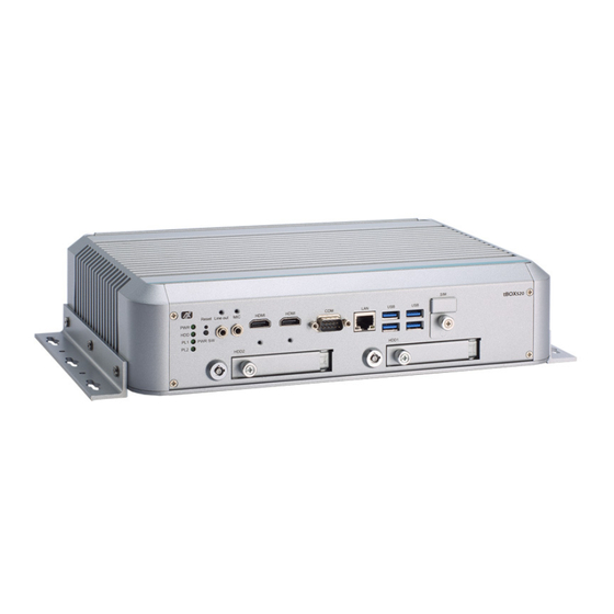
Series User’s Manual SECTION 1 INTRODUCTION This chapter contains general information and detailed specifications of the tBOX520-ADL-MR. Chapter 1 includes the following sections: ◼ General Description ◼ System Specification ◼ Dimensions ◼ I/O Outlets ◼ Package List General Description The tBOX520-ADL-MR is an embedded system that supports the 12th Gen. -
Page 10: System Specifications
Series User’s Manual ⚫ Reliable and Stable Design ◼ The tBOX520-ADL-MR adopts an advanced cooling system and rugged design that support 3 Grms w/ SSD for vibration, which makes it especially suitable for harsh environments and the best solution for on board surveillance, communication, intelligent video analysis, and etc. -
Page 11: System Specification
Series User’s Manual 1.2.3 System Specification ⚫ Watchdog Timer ◼ Reset supported; 255 levels, 1~255 sec. ⚫ Power Supply ◼ 24-110 VDC-in power supply ◼ Power Rate:3.5A@24VDC; 0.75A@110VDC ◼ Power Rate:5.5A@24VDC; 1.2A@110VDC (For internal PoE PSU SKU) ⚫ Operation Temperature ◼... -
Page 12: Dimensions
Series User’s Manual Dimensions The following diagrams show the dimensions and outlines of the tBOX520-ADL-MR. ▲ Top View (with wall mount) ▲ Bottom View (with wall mount) Introduction... - Page 13 Series User’s Manual ▲ Front View (with wall mount) ▲ Side View (with wall mount) ▲ Rear View: M12 DC-IN (with wall mount) Introduction...
-
Page 14: Packing List
Series User’s Manual Packing List The package bundled with your tBOX520-ADL-MR should contain the following items: ⚫ tBOX520-ADL-MR System Unit x 1 ⚫ Screw pack x 1 ⚫ Foot pad x 4 ⚫ Wall-mount bracket x 2 ⚫ Thermal pad for DDR, NVMe module ⚫... -
Page 15: Section 2 Hardware Installation
Series User’s Manual SECTION 2 HARDWARE INSTALLATION Chapter 2 will show you how to install the hardware into tBOX520-ADL-MR. Installing the Swappable HDD/SSD & Value-added Module (VAM) Step 1 Attach a piece of Mylar on the back of an HDD/SSD as shown. -
Page 16: Installing The Ddr Module And M.2 Nvme
Series User’s Manual Step 4 For VAM module installation, unscrew the top side screws (x4) and rear side screws (x2), and then remove the module slot cover. Step 5 Insert the value-added module (VAM) as shown below. Make sure the module is on the track and slide the module gently into the slot until it clicks in place. -
Page 17: Installing The Wall Mount Kits
Series User’s Manual Step 4 Loosen the four screws to remove the bracket and put the thermal pad on the slot. Step 5 Install the DDR module and M.2 module. Step 6 Place the thermal pad above the module and screw the bracket back. -
Page 18: Installing The Wireless Module
Series User’s Manual Step 4 Attach the wall mount to the system and fasten the screws tightly as shown below to complete the installation. Installing the Wireless Module Step 1 Loosen the screw and remove the cover. Hardware Installation... - Page 19 Series User’s Manual Step 2 Insert the SIM Card into the socket and push in. Then put back the cover and tighten the screw. SIM slot Wireless module insert slot S1(up) S2(down) CN10 Step 3 Install the wireless module into the slot and tighten the screws.
- Page 20 Series User’s Manual Step 4 Remove the antenna plug from one antenna hole on the system chassis, and prepare the antenna cable. Step 5 Make the antenna cable’s gold connector through the antenna hole on the system chassis and screw it tight with the antenna nut and gasket.
-
Page 21: Installing The Cable Fixing Plate
Series User’s Manual Installing the Cable Fixing Plate For HDMI: Step 1 Turn off the system and unplug the power cord. Step 2 To fasten the HDMI cable fixing plate (Figure 1) to the system, align the hole on the plate with the hole on the system chassis, insert the screw* into the holes, and tighten the screw to fasten the plate, as shown in Figure 2 below. - Page 22 Series User’s Manual This page is intentionally left blank. Hardware Installation...
-
Page 23: Section 3 Connector
Series User’s Manual SECTION 3 CONNECTOR Connectors Connectors connect to the CPU board with the other parts of the system. Loose or improper connection might cause problems. Make sure all connectors are properly and firmly connected before your turn on the system. -
Page 24: Serial Port Connector
Series User’s Manual 3.1.2 Serial Port Connector The COM1 port connector is a DB9 connector. The pin assignment of RS-232/RS-422/RS- 485 is listed in the following table. If you need the COM port to support RS-422 or RS-485, please set it up in BIOS settings. -
Page 25: Led Indicators
Series User’s Manual 3.1.4 LED Indicators Description LED Indicator Function Indicates power status. When the DC input is PWR/Green Power on connected, the LED will light on. Indicates storage status. The LED flashes HDD/Green HDD activity when storage is being accessed. -
Page 26: Lan Connector
Series User’s Manual 3.1.6 LAN Connector The RJ-45 LAN connectors can support 100/1000/2500 Mbps. Ethernet (optional) Description 100Base-T 1000/2500Base-T Transmit Data+ or Bidirectional BI_DA+ BI_DA- Transmit Data- or Bidirectional BI_DB+ Receive Data+ or Bidirectional N.C. BI_DC+ Not Connected or Bidirectional N.C. -
Page 27: Nanosim Card Connector
Series User’s Manual 3.1.7 NanoSIM Card Connector The NanoSIM Card slot is an ISO 7816 standard 6-pin connector for the PCI Express M.2/Mini Card. Signal SIM_PWR SIM_RESET SIM_CLK SIM_VPP SIM_DATA SIM slot Wireless module insert slot CN10 Connector... -
Page 28: Pci-Express Mini Card Connector (Cn10)
Series User’s Manual 3.1.8 PCI-Express Mini Card Connector (CN10) The PCI Express Mini Card connectors support 1x PCI Express lane and 2x USB 2.0 lanes. A PCI Express Mini Card can be applied to either PCI Express or USB 2.0. It’s very helpful that we have designed the USB 2.0 and PCI Express lanes in the same slot for an interface... -
Page 29: Antenna Opening
Series User’s Manual 3.1.9 Antenna Opening Profile opening is reserved for Wi-Fi/3G/4G/5G antennas. 3.1.10 HDD Tray Locker Lock and secure the swappable HDD/SSD bay. Status Diagram Unlocked Locked 3.1.11 Restore BIOS Optimal Default Settings(SW1) Function Setting Normal operation (Default) -
Page 30: 2280 Key M Nvme Ssd (Cn11)
Series User’s Manual 3.1.12 M.2 2280 Key M NVMe SSD (CN11) The M.2 2280 Key M NVM Express SSD for storage. Signal Signal Signal Signal +3.3V +3.3V PERn3 PERp3 LED_1# PETn3 +3.3V PETp3 +3.3V +3.3V PERn2 +3.3V PERp2 PETn2... -
Page 31: Key B+M.2 Key E (Cn8)
Series User’s Manual 3.1.13 M.2 Key B+M.2 Key E (CN8) Key B Signal Signal Signal Signal CONFIG_3 +3.3V +3.3V Full Card PWR USB_D+ W_DISABLE1# USB_D- GPIO_9 Key B Key B Key B Key B Key B Key B Key B... - Page 32 Series User’s Manual Key E Signal Signal Signal Signal +3.3V USB_D+ +3.3V USB_D- CONNECTOR KEY E CONNECTOR CONNECTOR CONNECTOR CONNECTOR KEY E KEY E KEY E KEY E CONNECTOR CONNECTOR CONNECTOR KEY E KEY E KEY E PETp0 PETn0...
-
Page 33: 3.1.14 Value-Added Module Specification
Series User’s Manual 3.1.14 Value-Added Module Specification Module Description The system offers two expansion I/O module slots, Value-added Module, to support expanding the I/O functions of tBOX520. For detailed specifications of each VAM, please refer to the quick manual of the individual module. - Page 34 Series User’s Manual VAM400: Video & Audio-in + mini PCIe VAM102: 4x isolated CANbus 2.0A/B capture card VAM600: Mini PCI Express + SIM This page is intentionally left blank. Connector...
-
Page 35: Section 4 Ami Bios Setup Utility
Series User’s Manual SECTION 4 AMI BIOS SETUP UTILITY The AMI UEFI BIOS provides users with a built-in setup program to modify basic system configuration. All configured parameters are stored in a 16MB flash chip to save the setup information whenever the power is turned off. -
Page 36: Navigation Keys
Series User’s Manual Navigation Keys The BIOS setup/utility uses a key-based navigation system called hot keys. Most of the BIOS setup utility hot keys can be used at any time during the setup navigation process. These keys include <F1>, <F2>, <Enter>, <ESC>, <Arrow>... -
Page 37: Main Menu
Series User’s Manual Main Menu When you first enter the setup utility, you will enter the Main setup screen. You can always return to the Main setup screen by selecting the Main tab. System Time/Date can be set up as described below. The Main BIOS setup screen is shown below. -
Page 38: Advanced Menu
Series User’s Manual Advanced Menu The Advanced menu allows users to set the configuration of the CPU and other system devices. You can select any of the items in the left frame of the screen to go to the sub menus: ►... - Page 39 Series User’s Manual ⚫ Trusted Computing This sub-menu will allow you to enable/disable Trusted Platform Module (TPM) support and to configure the TPM State. Select Trusted Computing and press Enter to access the sub-menu. Select the Security Device Support item to enable the TPM device.
- Page 40 Series User’s Manual ⚫ CPU Configuration This screen shows the CPU configuration, and you can change the value of the selected option. ⚫ ➢ Hyper-Threading ⚫ Enable or disable Hyper-Threading Technology. When enabled, it allows a single physical processor to multitask as multiple logical processors. When disabled, only one thread per enabled core is enabled.
- Page 41 Series User’s Manual ⚫ Hardware Monitor This screen shows the Hardware Health Configuration. ⚫ ⚫ AMI BIOS Setup Utility...
- Page 42 Series User’s Manual ⚫ F81804 Super IO Configuration You can use this screen to select options for the Super IO Configuration, and change the value of the selected option. A description of the selected item appears on the right side of the screen. For items marked with “”, please press <Enter>...
- Page 43 Series User’s Manual ⚫ Serial Port 1 Configuration Use these items to set parameters related to serial port 1. ➢ Serial Port 1 This item allows you to use it as RS232/422/485. The default is RS232. AMI BIOS Setup Utility...
- Page 44 Series User’s Manual ⚫ Storage Configuration This screen shows storage information. AMI BIOS Setup Utility...
- Page 45 Series User’s Manual ⚫ SATA Configuration During system boot up, the BIOS automatically detects the presence of SATA devices. In the SATA Configuration menu, you can see the hardware currently installed in the SATA ports. ➢ SATA Controller(s) Enable or disable the SATA Controller feature. The default is Enabled.
- Page 46 Series User’s Manual ⚫ NVMe Configuration This screen shows NVMe device information. AMI BIOS Setup Utility...
- Page 47 Series User’s Manual ⚫ USB Configuration This screen shows USB configuration. AMI BIOS Setup Utility...
- Page 48 Series User’s Manual ⚫ VMD setup menu ➢ VMD Setup Menu VMD Configuration settings. The default is Disabled. AMI BIOS Setup Utility...
- Page 49 Series User’s Manual How to Create Raid? Step 1. In SATA Configuration, Enabled VMD Controller and save&reset. Step2. After Restart, enter del to Bios Setup Menu. In Advanced Page, choose Intel(R) Rapid Storage Technology. AMI BIOS Setup Utility...
- Page 50 Series User’s Manual Step3. In Intel(R) Rapid Storage Technology page. Choose RAID Volume. AMI BIOS Setup Utility...
- Page 51 Series User’s Manual Step4. Select the disk to be merged. Step5. Finally, implement create Volume. AMI BIOS Setup Utility...
- Page 52 Series User’s Manual ⚫ Serial port Console Redirection The settings specify how the host computer and the remote computer (which the user is using) will exchange data. Both computers should have the same or compatible settings. ➢ Console Redirection Console Redirection.
- Page 53 Series User’s Manual ⚫ Device Configuration AMI BIOS Setup Utility...
- Page 54 Series User’s Manual AMI BIOS Setup Utility...
- Page 55 Series User’s Manual ⚫ Smart Ignition Configuration Press Enter to access the sub-menu. Calculated based on the 24-hour military-time clock. BIOS menu item Description Ignition Enabled Management Switch to In-Vehicle mode *Note: IGN signal will be t only riggered when DCIN pin5 IGN connected to VCC.
- Page 56 Series User’s Manual BIOS menu item Description AMI BIOS Setup Utility...
- Page 57 Series User’s Manual Activate Voltage Trigger The system turns on only when the voltage delivered by the power source is higher than the value you set here. Low Voltage Trigger The system will begin the countdown once voltage drops below the value you set here.
-
Page 58: Chipset Menu
Series User’s Manual Chipset Menu The Chipset menu allows users to change the advanced chipset settings. You can select any of the items in the left frame of the screen to go to the sub menus: ⚫ System Agent (SA) Configuration ⚫... - Page 59 Series User’s Manual ⚫ System Agent (SA) Configuration This screen shows the memory information. AMI BIOS Setup Utility...
- Page 60 Series User’s Manual ⚫ PCH-IO Configuration Display ME firmware version and ME firmware SKU. AMI BIOS Setup Utility...
-
Page 61: Security Menu
Series User’s Manual Security Menu The security menu allows users to change the security settings for the system. ➢ Administrator Password This item indicates whether an administrator password has been set (installed or uninstalled). ➢ User Password This item indicates whether an user password has been set (installed or uninstalled). - Page 62 Series User’s Manual ⚫ Secure Boot This item is available on the UEFI firmware to provide a secure environment. AMI BIOS Setup Utility...
-
Page 63: Boot Menu
Series User’s Manual Boot Menu The Boot menu allows users to change boot options of the system. You can select any of the items in the left frame of the screen to go to the sub menu: ➢ Setup Prompt Timeout Set the number of seconds to wait for setup activation key. -
Page 64: Save & Exit Menu
Series User’s Manual Save & Exit Menu The Save & Exit menu allows users to determine whether to accept their modifications to the system configuration, or to keep default settings for optimal fail-safe performance. ➢ Save Changes and Exit When finishing the system configuration settings, select this option to leave Setup and return to Main Menu. - Page 65 Series User’s Manual ➢ Save Changes When finishing the system configuration settings, select this option to save changes. Select Save Changes from the Save & Exit menu and press <Enter>. Select Yes to save changes. ➢ Discard Changes Select this option to quit Setup without making any permanent changes to the system configuration.
- Page 66 Series User’s Manual This page is intentionally left blank. AMI BIOS Setup Utility...
-
Page 67: Appendix Awatchdog Timer
Series User’s Manual APPENDIX A WATCHDOG TIMER About Watchdog Timer Software stability is a major issue in most applications. Some embedded systems are not watched by an operator for 24 hours. It is usually too late to wait for someone to reboot when computer hangs. The systems need to be able to reset automatically when things go wrong. - Page 68 Series User’s Manual hinstLibDLL = LoadLibrary(TEXT("diodll.dll")); if (hinstLibDLL == NULL) //MessageBox("Load diodll dll error", "", MB_OK); if (hinstLibDLL) lpFnDll_Get_IO = (LPFNDLLGETIOSPACE)GetProcAddress(GetModuleHandle("diodll.dll"), "GetIoSpaceByte"); lpFnDll_Set_IO = (LPFNDLLSETIOSPACE)GetProcAddress(GetModuleHandle("diodll.dll"), "SetIoSpaceByte"); printf("Input Watch Dog Timer type, 1:Second ; 2:Minute :"); scanf("%d",&unit); printf("\nInput Timer to countdown:");...
- Page 69 Series User’s Manual //set WDT Timer lpFnDll_Set_IO(0x2e, 0xF6); lpFnDll_Set_IO(0x2f, WDTtimer); //set watchdog time unit to min lpFnDll_Set_IO(0x2e, 0xF5); WDTDATA = lpFnDll_Get_IO(0x2f); WDTDATA = setbit(WDTDATA, 3); lpFnDll_Set_IO(0x2f, WDTDATA); //start watchdog counting lpFnDll_Set_IO(0x2e, 0xF5); WDTDATA = lpFnDll_Get_IO(0x2f); WDTDATA = setbit(WDTDATA, 5);...
- Page 70 Series User’s Manual This page is intentionally left blank. Watchdog Timer...
-
Page 71: Appendix B Windows Power Button Setting
Series User’s Manual APPENDIX B WINDOWS POWER BUTTON SETTING Please enter the power button setting through the PC console, and then follow below steps to complete the setting. Windows Power Button Setting... - Page 72 Series User’s Manual When IGN function has been used, the power button’s setting must be switched to “Shut down” as below. Then the system can be shut down normally, after IGN has been turned off. Windows Power Button Setting...
- Page 73 Series User’s Manual Windows Power Button Setting...
- Page 74 Series User’s Manual This page is intentionally left blank. Windows Power Button Setting...
- Page 75 Series User’s Manual APPENDIX C Programmable LED If the user needs to use this function, please contact FAE for further information. Programmable LED...
Need help?
Do you have a question about the tBOX520-ADL-MR Series and is the answer not in the manual?
Questions and answers