Table of Contents
Advertisement
Quick Links
Advertisement
Table of Contents

Related Manuals for AXIOMTEK UST210-83K-FL Series


Summary of Contents for AXIOMTEK UST210-83K-FL Series
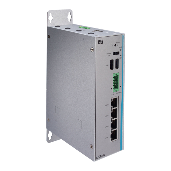
- Page 1 UST210-83K-FL Series Robust DIN-rail Fanless Embedded System User’s Manual...
- Page 2 Axiomtek does not make any commitment to update the information in this manual. Axiomtek reserves the right to change or revise this document and/or product at any time without notice.
-
Page 3: Safety Precautions
Safety Precautions Before getting started, please read the following important safety precautions. The UST210-83K-FL does not come equipped with an operating system. An operating system must be loaded first before installing any software into the computer. Be sure to ground yourself to prevent static charge when installing the internal components. -
Page 4: Classification
Classification Degree of production against electric shock: not classifi ed Degree of protection against the ingress of water: IP20 Equipment not suitable for use in the presence of a flammable anesthetic mixture with air or with oxygen or nitrous oxide. Mode of operation: Continuous Type of protection against electric shock: C lass I equipment General Cleaning Tips... - Page 5 Cleaning Tools Although many companies have created products to help improve the process of cleaning your computer and peripherals users can also use household items to clean their computers and peripherals. Below is a listing of items you may need or want to use while cleaning your computer or computer per ipherals.
-
Page 6: Scrap Computer Recycling
Trademarks Acknowledgments Axiomtek is a trademark of Axiomtek Co., Ltd. IBM, PC/AT, PS/2, VGA are trademarks of International Business Machines Corporation. ®... -
Page 7: Table Of Contents
Table of Contents Safety Precautions ....................iii Classification ......................iv General Cleaning Tips ..................iv Scrap Computer Recycling ................... vi SECTION 1 INTRODUCTION................. 1 General Description ................1 System Specifications ............... 2 1.2.1 CPU ........................2 1.2.2 BIOS ........................2 1.2.3 System Memory .................... - Page 8 About Watchdog Timer ................... 45 How to Use Watchdog Timer ................45 APPENDIX B POWER BUTTON SETTING FOR WINDOWS SOFTWARE 47 viii...
-
Page 9: Section 1 Introduction
UST210-83K-FL User’s Manual SECTION 1 INTRODUCTION This chapter contains general information and detailed specifications of the UST210-83K-FL. Section 1 includes the following sections: ◼ General Description ◼ System Specification ◼ Dimensions ◼ I/O Outlets General Description The UST210-83K-FL fanless embedded system is an ideal solution for communications control and protocol converter applications in harsh environments. -
Page 10: System Specifications
UST210-83K-FL User’s Manual ⚫ Features ◼ Fanless design ◼ Wide temperature operation range of -40°C - +70°C ◼ Supports 4 x 10/100/1000 Base-T Ethernets ◼ Two SKUs: 1 x CANBUS port + 1 x COM port supporting RS-232/422/485 (4 wires) 2 x COM ports support RS-232/422/485 (4 wires) ◼... -
Page 11: Ethernet Ports
UST210-83K-FL User’s Manual 1.2.5 Ethernet Ports ⚫ LAN chip: Intel Ethernet Controller I211. ⚫ Four RJ-45 connectors support 10/100/1000 Base-T Ethernet with 1.5KV magnetic isolated protection. ⚫ Supports Power of Ethernet IEEE802.3 AF/AT 30W (PoE model type only) by using the alternative A & B connection method to carry the power. The UST210 is designed to function as a PSE device. -
Page 12: Storage
Supports High Speed Mode115.2 Kbps, Up to 1.5 Mbps ⚫ Pin define is listed as follows: RS232 RS422 RS485 RS232 RS422 RS485 1.2.11 Power ⚫ Wide-range 9 - 36VDC (typical 12/24VDC) power input with terminal block. ⚫ OVP and RVP protection. ⚫ Supports Axiomtek Smart Ignition. Signal Introduction... -
Page 13: Power & Reset Button
UST210-83K-FL User’s Manual 1.2.12 Power & Reset Button ⚫ AT auto power on. ⚫ Power button setting for software must be set up first. ⚫ One reset button. Note: Power button setting instructions for Windows software is offered in APPENDIX B for reference. -
Page 14: Watchdog Timer (Wdt)
UST210-83K-FL User’s Manual 1.2.14 WatchDog Timer (WDT) ⚫ 1~255 seconds or minutes; up to 255 levels 1.2.15 Restore BIOS Optimal Defaults (SW1) ⚫ Press the tact switch (SW 1) to restore optimal BIOS defaults. 1.2.16 System LED ⚫ The table below summarizes the functional descriptions of the LED indicators and their corresponding colors. -
Page 15: System I/O Outlets
UST210-83K-FL User’s Manual 1.2.22 System I/O Outlets ⚫ One terminal block 2x5 pin male connector, 2 SKUs available: COM x1 + CAN x1 COM x2 ⚫ One HDMI connector ⚫ Four 10/100/1000 Base-T RJ-45 with 1.5KV magnetic isolated protection. ⚫ Two USB 3.0 ports ⚫... -
Page 16: Dimensions
UST210-83K-FL User’s Manual Dimensions The following diagrams show you the dimensions and outlines of the UST210-83K- Model without PoE Model with PoE Introduction... -
Page 17: I/O Outlets
UST210-83K-FL User’s Manual I/O Outlets The following figures show you the I/O outlets on the front view and top view of the UST210-83K-FL. (Without PoE) (with PoE) Introduction... - Page 18 UST210-83K-FL User’s Manual (Without PoE) (With PoE) Introduction...
-
Page 19: Section 2 Hardware Installation
UST210-83K-FL User’s Manual SECTION 2 HARDWARE INSTALLATION The UST210-83K-FL is convenient for your various hardware configurations, such as memory modules and mSATA drives. Section 2 will show you how to install the hardware. Installing the Memory Module Step 1 Turn off the system. Step 2 Loosen all screws from the cover and flip the cover to the... -
Page 20: Installing The Msata
UST210-83K-FL User’s Manual Installing the mSATA Step 1 Insert the mSATA into the slot. Step 2 Fasten the screws tightly. Hardware Installation... -
Page 21: Installing The Wireless Module
UST210-83K-FL User’s Manual Installing the Wireless Module Step 1 Pull the SIM socket backward to unlock, and flip the cover to open Step 2 Insert the SIM Card into the socket and put it back down. Then slide the socket forward to lock it in place. Step 3 Insert the wireless module into the slot and fasten the screw. - Page 22 UST210-83K-FL User’s Manual Step 4 Remove the antenna plug from one antenna hole on the system chassis, and prepare the antenna cable. Step 5 Make the antenna cable’s gold connector through the antenna hole on the system chassis, and screw it tight with the antenna nut and gasket. Step 6 Screw the RF antenna to the gold connector.
-
Page 23: Installing The Hard Disk
UST210-83K-FL User’s Manual Installing the Hard Disk Step 1 Loosen the bracket screw and take off the bracket, and apply the HDD pad on the bracket. Step 2 Insert the hard disk and screw the bracket to the system chassis. Hardware Installation... -
Page 24: Installing The Din-Rail Mount And Wall Mount Kits
UST210-83K-FL User’s Manual Installing the DIN-rail Mount and Wall Mount Kits The UST210-83K-FL provides DIN-rail and Wall Mount kits that customers can install as below: Method 1: DIN-rail Mount Step 1 Prepare the DIN-rail mount assembling components (screws and bracket) ready. Step 2 Assemble the bracket to the system unit and fasten all screws tight. - Page 25 UST210-83K-FL User’s Manual Step 2 Align the positioning notches on the wall mount bracket to the edges of the system unit. Make sure the screw hole chamfers face upward and then screw the bracket firmly to the system unit. (Without PoE) (With PoE) Hardware Installation...
-
Page 26: 2.6 Installing The Cable Fixing Plate
UST210-83K-FL User’s Manual 2.6 Installing the Cable Fixing Plate Step 1 Turn off the system and unplug the power cord. Step 2 To fasten the HDMI cable fixing plate (Figure 1) to the system, position the hole on the plate against the hole on the system chassis, insert the screw into the holes, and turn the screw tightly to fasten the plate, as shown in Figure 2 below. -
Page 27: Section 3 Ami Uefi Bios Utility
UST210-83K-FL User’s Manual SECTION 3 AMI UEFI BIOS UTILITY The AMI UEFI BIOS provides users with a built-in Setup program to modify basic system configuration. All configured parameters are stored in a flash backup to save the Setup information whenever the power is turned off Entering Setup To enter the setup screens, follow the steps below: Turn on the computer and press the <Del>... -
Page 28: Advanced Features
UST210-83K-FL User’s Manual Advanced Features This Advanced menu allows users to configure and improve your system, or to set up some system features according to your preference. You can select any of the items in the left frame of the screen to go to the sub menus: ►... - Page 29 UST210-83K-FL User’s Manual CPU Configuration ⚫ Scroll to this item and press <Enter> to view the CPU Configuration information. (Please refer to below graphics.) AMI UEFI BIOS Utility...
- Page 30 UST210-83K-FL User’s Manual SATA Configuration ⚫ Scroll to this item and press <Enter> to view the SATA Configuration information. (Please refer to below graphics.) AMI UEFI BIOS Utility...
- Page 31 UST210-83K-FL User’s Manual USB Configuration ⚫ Scroll to this item and press <Enter> to view the USB Configuration information. (Please refer to below graphics.) AMI UEFI BIOS Utility...
- Page 32 UST210-83K-FL User’s Manual H/W Monitor ⚫ Scroll to this item and press <Enter> to view the hardware status items under monitoring. (Please refer to below graphics.) AMI UEFI BIOS Utility...
- Page 33 UST210-83K-FL User’s Manual F81804 Super IO Configuration ⚫ The default setting for all serial ports is RS232. You can change the setting by selecting the value you want in each COM port type. The system supports RS422 and RS485 modes as well as high-speed mode. You can enable High-speed mode, which can be selected in the BIOS menu.
- Page 34 UST210-83K-FL User’s Manual AMI UEFI BIOS Utility...
- Page 35 UST210-83K-FL User’s Manual Trust Computing ⚫ This sub-menu will allow you to enable/disable Trusted Platform Module (TPM) support and to configure the TPM State. Select Trusted Computing and press Enter to access the sub-menu. Select the Security Device Support item to enable the TPM device. AMI UEFI BIOS Utility...
- Page 36 UST210-83K-FL User’s Manual AMI UEFI BIOS Utility...
- Page 37 UST210-83K-FL User’s Manual DIO Configuration ⚫ The DIO Modification default setting is “disable”. If the setting is changed to “enable”, you can load manufacture default and program DIO setting. (Please refer to below graphics.) AMI UEFI BIOS Utility...
- Page 38 UST210-83K-FL User’s Manual AMI UEFI BIOS Utility...
- Page 39 UST210-83K-FL User’s Manual AMI UEFI BIOS Utility...
- Page 40 UST210-83K-FL User’s Manual AMI UEFI BIOS Utility...
- Page 41 UST210-83K-FL User’s Manual PoE Configuration ⚫ Power over Ethernet (PoE) describes any of several standard or ad-hoc systems which pass electrical power along with data on twisted pair Ethernet cabling. ※ This function is only available for UST210-83K-E3940-4POE-COM-CAN-TVDC or UST210-83K-E3940-4POE-2COM -TVDC. This menu allows users to set the power and enable/disable a specific port.
- Page 42 Enable/Disable a specific POE port and display all port status. Smart Ignition Management ⚫ The Smart Ignition Management setting includes Axiomtek DIO settings. Press Enter to access the sub-menu. Calculated based on the 24-hour military-time clock. AMI UEFI BIOS Utility...
- Page 43 UST210-83K-FL User’s Manual BIOS menu item Description Ignition Enabled Management Switch to In-Vehicle mode Disabled Switch to AT/Railway mode *PSU and system will reset after setting is saved Auto Power On Enabled System will turn on automatically under below conditions - Manually disconnects and reconnects system power - Power interruption: Resumes power after...
- Page 44 UST210-83K-FL User’s Manual BIOS menu item Description Activate Voltage Trigger The system only turns on when the voltage delivered by the power source is higher than the value you set here. Low Voltage Trigger The system will begin countdown stage once voltage drops below the value you set here.
-
Page 45: Chipset Feature
UST210-83K-FL User’s Manual set. Additionally, if power source voltage is lower than the setup value it will cause the system to turn off as well. Chipset Feature This section contains fully optimized chipset features in the system. AMI UEFI BIOS Utility... -
Page 46: Security
UST210-83K-FL User’s Manual Security The Security menu allows users to enhance system security by setting an administrator password and a user password. No password has been set in the default setting. (Please refer to below graphics.) AMI UEFI BIOS Utility... - Page 47 UST210-83K-FL User’s Manual Note: The BIOS default has no password. The user must remember the password after creating one. If the user forgets the password RMA is the only solution. AMI UEFI BIOS Utility...
-
Page 48: Boot Type
UST210-83K-FL User’s Manual Boot Type The Boot menu allows users to change boot options of the system, providing UEFI, Legacy, and Compatible modes to select from. The default setting boot mode is [UEFI Mode]. (Please refer to below graphics.) AMI UEFI BIOS Utility... - Page 49 UST210-83K-FL User’s Manual The Boot Option Priorities can be set by selecting Boot Option #1, #2… (Please refer to below graphics.) AMI UEFI BIOS Utility...
-
Page 50: Save & Exit
UST210-83K-FL User’s Manual Save & Exit The Save & Exit menu allows users to determine whether or not to accept their modifications to the system configuration, or to keep default values for optimal fail-safe performance. (Please refer to below graphics.) BIOS Description menu item... - Page 51 UST210-83K-FL User’s Manual Save After completing the system configuration changes, select this option to save Changes changes. Select Save Changes from the Save & Exit menu and press <Enter>. Select Yes to save changes. Discard Select this option to quit Setup without making any permanent changes to the Changes system configuration.
- Page 52 UST210-83K-FL User’s Manual This page is intentionally left blank. AMI UEFI BIOS Utility...
-
Page 53: Appendix Awatchdog Timer
UST210-83K-FL User’s Manual APPENDIX A WATCHDOG TIMER About Watchdog Timer After the system stops working for a while, it can be auto-reset by the watchdog timer. The integrated watchdog timer can be set up in the system reset mode by program. How to Use Watchdog Timer The following example enables configuration using a debug tool. - Page 54 UST210-83K-FL User’s Manual This page is intentionally left blank. Watchdog Timer...
- Page 55 UST210-83K-FL User’s Manual APPENDIX B POWER BUTTON SETTING FOR WINDOWS SOFTWARE Please enter the power button setting through the PC console, and then follow below pictures to complete the setting. Power Button Setting For Window Software...
- Page 56 UST210-83K-FL User’s Manual Please check if the action of pressing power button is “Shut down” to let ACC work normally and prevent unexpected hard shut down. Power Button Setting For Window Software...
- Page 57 UST210-83K-FL User’s Manual Power Button Setting For Window Software...
Need help?
Do you have a question about the UST210-83K-FL Series and is the answer not in the manual?
Questions and answers