Table of Contents
Advertisement
Quick Links
Advertisement
Table of Contents

Subscribe to Our Youtube Channel
Related Manuals for AXIOMTEK UST100-504-FL Series


Summary of Contents for AXIOMTEK UST100-504-FL Series
- Page 1 UST100-504-FL Series Embedded System User’s Manual...
-
Page 2: Disclaimers
Disclaimers This manual has been carefully checked and believed to contain accurate information. Axiomtek Co., Ltd. assumes no responsibility for any infringements of patents or rights of any third party, or any liability arising from such uses. Axiomtek does not warrant or assume any legal liability or responsibility for the accuracy, completeness or usefulness of any information in this document. -
Page 3: Safety Precautions
Safety Precautions Before getting started, please read the following important safety precautions. The UST100-504-FL does not come with an operating system which must be loaded first before installation of any software into the computer. Be sure to ground yourself to prevent static charge when installing any internal components. -
Page 4: Classifications
Classifications Degree of production against electric shock: not classified Degree of protection against ingress of water: IP30 Equipment not suitable for use in the presence of a flammable anesthetic mixture with air, oxygen or nitrous oxide. Mode of operation: Continuous... -
Page 5: General Cleaning Tips
General Cleaning Tips Please keep the following precautions in mind while understanding the details fully before and during any cleaning of the computer and any components within. A piece of dry cloth is ideal to clean the device. Be cautious of any tiny removable components when using a vacuum cleaner to absorb dirt on the floor. -
Page 6: Scrap Computer Recycling
Scrap Computer Recycling Please inform the nearest Axiomtek distributor as soon as possible for suitable solutions in case computers require maintenance or repair; or for recycling in case computers are out of order. Trademarks Acknowledgments Axiomtek is a trademark of Axiomtek Co., Ltd. -
Page 7: Table Of Contents
Table of Contents Disclaimers ......................ii Safety Precautions ....................iii Classifications ....................... iv General Cleaning Tips ................... v Scrap Computer Recycling ................... vi SECTION 1 INTRODUCTION ................ 1 General Descriptions ................. 1 System Specifications ............... 2 1.2.1 CPU ........................2 1.2.2 System Specifications .................. - Page 8 Boot Menu ..................52 Save & Exit Menu ................53 APPENDIX A WATCHDOG TIMER .............. 55 About Watchdog Timer .................. 55 How to Use the Watchdog Timer ..............55 Sample Program ....................55 viii...
-
Page 9: Section 1 Introduction
UST100-504-FL Series user’s Manual SECTION 1 INTRODUCTION This section contains general information and a detailed specification of the UST100-504-FL. Section 1 consists of the following sub-sections: General Descriptions System Specifications Dimensions I/O Outlets Packing List 1.1 General Descriptions... -
Page 10: System Specifications
UST100-504-FL Series user’s Manual Features ® ® Core™ i7/i5/i3 & Celeron LGA1151 socket 7 generation Intel ® processor (Kaby Lake / sky lake) with Intel H110 Supporting wide range of DC power input from 9 to 36VDC ... -
Page 11: System Specifications
Vibration Endurance 3 Grm with SSD (5-500Hz, X, Y, Z directions) 1 Grm with HDD (5-500Hz, X, Y, Z directions) 2 Grm with HDD & Axiomtek Anti-Vibration Kit (5~500Hz, X,Y, Z directions)* *Please contact Axiomtek for details. Introduction... -
Page 12: Driver Contents
185 mm (7.09”) (W ) x 150 mm (5.91”) (D) x 65.15 mm (2.56”) (H) 【Note】: All specifications and images are subject to change without notice. 1.2.3 Driver Contents Please download the drivers from the Axiomtek official website. Chipset ... -
Page 13: Dimensions
UST100-504-FL Series user’s Manual 1.3 Dimensions The following diagrams show the dimensions and outlines of the UST100-504-FL. Introduction... -
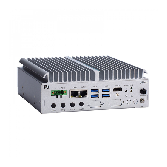
Page 14: I/O Outlets
HDD screws x 4 Terminal block x 1 Wall mount kit x1 Wall mount kit screws x 4 Mini Card slot screws x 3 Please contact an Axiomtek distributor immediately if any of the abovementioned items is missing. Introduction... -
Page 15: Section 2 Hardware Installation
UST100-504-FL Series user’s Manual SECTION 2 HARDWARE INSTALLATION The UST100-504-FL is convenient for various hardware configurations, such as CPU, DRAM, HDD (Hard Disk Drive), SSD (Solid State Drive), and PCI Express Mini Card modules. Section 2 contains guidelines for hardware installation. -
Page 16: Installing 2.5" Sata Device
UST100-504-FL Series user’s Manual Step 7 Flip the system back to its upright position and slide the system back onto the bottom cover and fasten all screws to complete installation. 2.2 Installing 2.5” SATA Device Step 1 Turn off the system and unplug the power cord. - Page 17 UST100-504-FL Series user’s Manual Step 6 Position the screw holes on the HDD/SSD against the holes on the SATA drive tray. Then screw the HDD/SSD firmly to the tray with the four supplied screws, as illustrated below. Step 7 Align the screw holes on the edges of the SATA drive tray to the screw posts on the inside of the chassis.
- Page 18 UST100-504-FL Series user’s Manual Step 9 Use the cable clips to fasten the SATA cable to the chassis and insert connector. Step 10 Slide the system back onto the bottom cover and fasten all screws to complete installation. Hardware Installation...
-
Page 19: Installing Msata Module
UST100-504-FL Series user’s Manual 2.3 Installing mSATA Module 【Note】 The MC2 card slot on the UST100-504-FL is a multi-functional slot that supports mSATA, PCIe and USB interfacing. To use the MC2 slot for connecting an mSATA card, the user will need to enter BIOS to modify MC2 configuration settings. - Page 20 UST100-504-FL Series user’s Manual Step 6 Slide the system back onto the bottom cover and fasten all screws to complete installation. Hardware Installation...
-
Page 21: Installing 4G/3G Module
UST100-504-FL Series user’s Manual 2.4 Installing 4G/3G Module Step 1 Turn off the system and unplug the power cord. Step 2 Remove the screws on both sides of the system. Step 3 Pull the main system away from its bottom cover, flip the system over 180 degrees and put it upside down. - Page 22 UST100-504-FL Series user’s Manual Step 7 Unplug all cables. Step 8 Remove the black antenna plug cover. Step 9 Insert the end of the RF cable through the antenna hole. Step 10 Screw the end of the RF cable tightly with the antenna nut and gasket.
- Page 23 UST100-504-FL Series user’s Manual Step 15 Screw the external RF antenna to the end of the RF cable tightly to complete installation. Hardware Installation...
-
Page 24: Installing The Wall Mount Kit
UST100-504-FL Series user’s Manual 2.5 Installing the Wall Mount Kit Step 1 Turn off the system and unplug the power cord. Step 2 Take out the wall mount kit and mounting screws from the accessory package. Step 3 Locate the wall mount screw holes on both sides of the system . Screw the wall mount brackets tightly to the system, as illustrated below. -
Page 25: Installing The Cable Fixing Plate
UST100-504-FL Series user’s Manual 2.6 Installing the Cable Fixing Plate Step 1 Turn off the system and unplug the power cord. Step 2 Loosen and remove the fixing screw located below the HDMI port. Step 3 To fasten the HDMI cable fixing plate to the system, position the hole... - Page 26 UST100-504-FL Series user’s Manual This page is intentionally left blank. Hardware Installation...
-
Page 27: Section 3 Dip Switch & Buttons & Connector Settings
UST100-504-FL Series user’s Manual SECTION 3 DIP SWITCH & BUTTONS & CONNECTOR SETTINGS Proper DIP switch settings configure the UST100-504-FL to meet various application needs. Hereby all jumper settings along with their default settings are listed for devices onboard. 3.1 Summary of DIP Switch Settings Proper DIP switch settings configure the UST100-504-FL to meet various application purposes. -
Page 28: Connectors
UST100-504-FL Series user’s Manual 3.2 Connectors Please refer to pin assignments below: 3.2.1 DC-in Power Connector The system supports the 9~36V (Default 12/24V) DC-in connector for system power input. Pins Signals ACC (Ignition) ( Figure 1 ) ( Figure 2 ) 【Note】Connect the DC-in power connector for the UST100-504-FL in-vehicle... -
Page 29: Hdmi Connector
UST100-504-FL Series user’s Manual 3.2.3 HDMI Connector The HDMI Rev1.4b (High-Definition Multimedia Interface) is a compact digital interface which is capable of transmitting high-definition video and high-resolution audio over a single cable. Pin definition follows HDMI Type A standard. 3.2.4 Remote Switch Connector The remote switch is ideal for a remote button, which can act as an power on/off button. -
Page 30: Audio Connector
UST100-504-FL Series user’s Manual 3.2.6 Audio Connector These two 3.5mm audio jacks are ideal for connecting TRS stereo plugs for Audio Mic-In and Audio Line-out. Signals Microphone In Line Out 3.2.7 Digital IO The UST100-504-FL supports 8CH digital input or output. Please refer to Chapter 4 for detailed BIOS settings. -
Page 31: Full-Size Pci Express Mini Card Slot
UST100-504-FL Series user’s Manual 3.2.8 Full-Size PCI Express Mini Card Slot Full-Size (MC1 & MC2) The UST100-504-FL supports dual full-size PCI-Express Mini Card slots. MC1 applies to either PCI-Express2.0 or USB 2.0 signals. MC2 applies to either PCI-Express2.0, USB 2.0 or SATA3.0 (mSATA) signals and complies with PCI-Express Mini Card Spec. - Page 32 UST100-504-FL Series user’s Manual Half-Size (MC3) MC3 applies to SATA3.0 (mSATA) signals. Users can install an mSATA card into this slot. Complies with PCI-Express Mini Card Spec. V1.2. The table follows PCI-Express Mini Card Spec. V1.2: Pins Signals Pins Signals +3.3Vaux...
-
Page 33: Buttons
UST100-504-FL Series user’s Manual 3.3 Buttons Proper configure the UST100-504-FL to meet various application purposes. The table s below list all default settings. 3.3.1 Power Button The power button is on the I/O side. It allows users to control power on/off state of the UST100-... - Page 34 UST100-504-FL Series user’s Manual This page is intentionally left blank. BIOS Setup Utility...
-
Page 35: Section 4 Bios Setup Utility
UST100-504-FL Series user’s Manual SECTION 4 BIOS SETUP UTILITY This section provides users with detailed descriptions in terms of how to set up basic system configurations through the BIOS setup utility. 4.1 Starting To enter the setup screens, follow the steps below: Turn on the computer and press the <Del>... -
Page 36: Main Menu
UST100-504-FL Series user’s Manual 4.3 Main Menu The Main Menu screen is the first screen users see when entering the setup utility. Users can always return to the Main setup screen by selecting the Main tab. System Time/Date can be set up as described below. -
Page 37: Advanced Menu
UST100-504-FL Series user’s Manual 4.4 Advanced Menu The Advanced menu also allows users to configure the CPU and other system devices. Users can select any items in the left frame of the screen to go to sub menus: ► Hardware Monitor ►... - Page 38 UST100-504-FL Series user’s Manual Hardware Monitor This screen displays the temperatures of the system and CPU as well as system voltages (VCORE, +3.3V, +12V and +5V). F81804 Super IO Configuration Use this screen to select options for the NCT6106D Super IO Configurations, and change the value of the selected option.
- Page 39 UST100-504-FL Series user’s Manual Serial Port 1 Serial port 1 is the communication interface for ignition configuration and is not available. Serial Port 2 (COM2) Configurations Use these items to set parameters related to serial port 2. Select Mode Use this option to set RS-232/RS-422/RS-485 mode High Speed Mode Enable communication speed up to 1.5 Mbps.
- Page 40 UST100-504-FL Series user’s Manual BIOS Setup Utility...
- Page 41 UST100-504-FL Series user’s Manual CPU Configuration This screen shows the CPU version and its detailed information. Intel Virtualization Technology It allows a hardware platform to run multiple operating systems separately and simultaneously, enabling one system to virtually function as several systems.
- Page 42 UST100-504-FL Series user’s Manual SATA and RST Configuration SATA Mode Selection AHCI (Advanced Host Controller Interface) mode is how SATA controller(s) operate. BIOS Setup Utility...
- Page 43 UST100-504-FL Series user’s Manual Mini Card Mode If the MC2 slot location is to be used for connecting an mSATA card, the user needs to change the Mini Card mode to mSATA and save it, so that the MC2 slot can function properly as an mSATA interface (default setting is PCIE).
- Page 44 UST100-504-FL Series user’s Manual PCH-FW Configuration This screen shows ME Firmware information. BIOS Setup Utility...
- Page 45 UST100-504-FL Series user’s Manual Trusted Computing Select the Security Device Support to enable or disable the TPM function. BIOS Setup Utility...
- Page 46 BIOS flash utility is a tool for flashing BIOS on setup menu. Follow the step to flash BIOS. Create a folder and rename it to Axiomtek on the root of USB storage (Ex: X:\Axiomtek). Copy the BIOS file to the Axiomtek folder (Ex: X:\Axiomtek\SBCXXXXXX.XXX, please refer the screenshot as below) (Note: The BIOS file name must contain the word “SBC”...
- Page 47 UST100-504-FL Series user’s Manual BIOS Setup Utility...
- Page 48 UST100-504-FL Series user’s Manual BIOS Setup Utility...
- Page 49 UST100-504-FL Series user’s Manual Device Configuration The DIO Modification default setting is “Disabled”. If the setting is changed for “enable”, you can load manufacture default and program DIO setting. (Please refer below graphics.) BIOS Setup Utility...
- Page 50 UST100-504-FL Series user’s Manual BIOS Setup Utility...
- Page 51 UST100-504-FL Series user’s Manual Ignition Configuration This menu allows users to configure settings related to vehicle ignition switch. Firmware Version Display Ignition controller firmware version. Use this screen to set ACC Timer. (1) ACC-ON Delay (T1): Set delay timer for system power on.
- Page 52 UST100-504-FL Series user’s Manual Advance Setting This item shows all information and voltage settings. BIOS Setup Utility...
- Page 53 UST100-504-FL Series user’s Manual Voltage Setting Voltage setting is designed to protect the lead-acid batteries and keep the system from running out of power when the lead-acid battery is low, so as not to drain the battery. (It is strongly recommended that users should avoid changing the defaults.) (1) Low Voltage: Notifies the system to shut down when voltage drops to the specified value.
- Page 54 UST100-504-FL Series user’s Manual Counter Setting (1) Low Voltage Counter: Sets shut down delay time. (2) Very Low Voltage Counter: Sets force turn off system power delay time. Function Spec range Default Value Unit Low Voltage Counter 1~60 Very Low Voltage Counter...
- Page 55 UST100-504-FL Series user’s Manual Load Default Setting This option allows you to restore to default settings and save factory defaults. BIOS Setup Utility...
-
Page 56: Chipset Menu
UST100-504-FL Series user’s Manual 4.5 Chipset Menu The Chipset menu allows users to change the advanced chipset settings. Users can select any of the items in the left frame of the screen to go to the sub menus: ► System Agent (SA) Configurations For items marked with “”, please press <Enter>... - Page 57 UST100-504-FL Series user’s Manual System Agent (SA) Configurations Memory Configuration Use this item to refer to the information related to system memory. BIOS Setup Utility...
- Page 58 UST100-504-FL Series user’s Manual BIOS Setup Utility...
- Page 59 UST100-504-FL Series user’s Manual Security Menu Administrator Password This item indicates whether an administrator password has been set (installed or uninstalled). User Password This item indicates whether a user password has been set (installed or uninstalled). BIOS Setup Utility...
-
Page 60: Boot Menu
UST100-504-FL Series user’s Manual 4.6 Boot Menu The Boot menu allows users to change boot options of the system. Setup Prompt Timeout Use this item to set up number of seconds to wait for setup activation key where 65535(0xFFFF) means indefinite waiting. -
Page 61: Save & Exit Menu
UST100-504-FL Series user’s Manual 4.7 Save & Exit Menu The Save & Exit menu allows users to load system configurations with optimal or fail-safe default values. Save Changes and Exit When users have completed the system configuration changes, select this option to leave Setup and return to Main Menu. - Page 62 UST100-504-FL Series user’s Manual Save Changes After completing the system configuration changes, select this option to save changes. Select Save Changes from the Save & Exit menu and press <Enter>. Select Yes to save changes. Discard Changes Select this option to quit Setup without making any permanent changes to the system configurations.
-
Page 63: Appendix Awatchdog Timer
How to Use the Watchdog Timer The user can configure the watchdog timer using the watchdog function included in the AXVIEW 2.0 software developed by Axiomtek, or using the debug.exe software released by Microsoft. NOTE: The related tool for setting WDT will not be available on the official downloads area. - Page 64 UST100-504-FL Series user’s Manual Disable watchdog timer STEP Sample code Note Enter configuration mode O 2E 87 Un-lock super I/O O 2E 87 Un-lock super I/O Select logic device O 2E 07 Select logic register O 2F 08 Switch to WDT device...
Need help?
Do you have a question about the UST100-504-FL Series and is the answer not in the manual?
Questions and answers