
Related Manuals for WAGO 750-652/040-000


Summary of Contents for WAGO 750-652/040-000
- Page 1 Manual WAGO-I/O-SYSTEM 750 XTR 750-652/040-000 Serial Interface RS-232/RS-485 XTR Freely Configurable, Extreme Version 1.3.0...
- Page 2 We wish to point out that the software and hardware terms as well as the trademarks of companies used and/or mentioned in the present manual are generally protected by trademark or patent. WAGO is a registered trademark of WAGO Verwaltungsgesellschaft mbH. Manual Version 1.3.0...
-
Page 3: Table Of Contents
WAGO-I/O-SYSTEM 750 XTR Table of Contents 750-652/040-000 Serial Interface RS-232/RS-485 XTR Table of Contents Notes about this Documentation ............. 6 Validity of this Documentation..............6 Copyright ....................6 Symbols ....................7 Number Notation ..................8 Font Conventions ................... 8 Important Notes ..................9 Legal Bases .................... - Page 4 7.2.4 DMX Operating Mode ..............52 7.2.5 Data Exchange Mode............... 53 Commissioning ..................54 Configuration and Parameterization with WAGO-I/O-CHECK ....54 8.1.1 RS-232 / RS-485 Serial Interface (Configuration Dialog) ....54 8.1.2 Toolbar on the Configuration Dialog ..........55 8.1.3 Process Image Size .................
- Page 5 WAGO-I/O-SYSTEM 750 XTR Table of Contents 750-652/040-000 Serial Interface RS-232/RS-485 XTR 8.3.6.2 Operation with Activated Continuous Send ........65 8.3.6.3 Mode when Receiving DMX Data ..........66 8.3.6.3.1 “DMX Receive” Operating Parameters ........67 8.3.6.3.2 “DMX Receive” Application Example ........68 8.3.7...
-
Page 6: Notes About This Documentation
This documentation is only applicable to the I/O module 750-652/040-000 (Serial Interface RS-232/RS-485 XTR). The I/O module 750-652/040-000 shall only be installed and operated according to the instructions in this manual, in the system description for the WAGO-I/O- SYSTEM 750 XTR and in the manual for the used fieldbus coupler/controller. -
Page 7: Symbols
WAGO-I/O-SYSTEM 750 XTR Notes about this Documentation 750-652/040-000 Serial Interface RS-232/RS-485 XTR Symbols Personal Injury! Indicates a high-risk, imminently hazardous situation which, if not avoided, will result in death or serious injury. Personal Injury Caused by Electric Current! Indicates a high-risk, imminently hazardous situation which, if not avoided, will result in death or serious injury. -
Page 8: Number Notation
Notes about this Documentation WAGO-I/O-SYSTEM 750 XTR 750-652/040-000 Serial Interface RS-232/RS-485 XTR Additional Information: Refers to additional information which is not an integral part of this documentation (e.g., the Internet). Number Notation Table 1: Number Notation Number Code Example Note... -
Page 9: Important Notes
2.1.1 Subject to Changes WAGO Kontakttechnik GmbH & Co. KG reserves the right to provide for any alterations or modifications. WAGO Kontakttechnik GmbH & Co. KG owns all rights arising from the granting of patents or from the legal protection of utility patents. -
Page 10: Technical Condition Of Specified Devices
These modules contain no parts that can be serviced or repaired by the user. The following actions will result in the exclusion of liability on the part of WAGO Kontakttechnik GmbH & Co. KG: •... -
Page 11: 2.1.4.1.2 Packaging
WAGO-I/O-SYSTEM 750 XTR Important Notes 750-652/040-000 Serial Interface RS-232/RS-485 XTR • Observe national and local regulations for the disposal of electrical and electronic equipment. • Clear any data stored on the electrical and electronic equipment. • Remove any added battery or memory card in the electrical and electronic equipment. -
Page 12: Safety Advice (Precautions)
Important Notes WAGO-I/O-SYSTEM 750 XTR 750-652/040-000 Serial Interface RS-232/RS-485 XTR Safety Advice (Precautions) For installing and operating purposes of the relevant device to your system the following safety precautions shall be observed: Do not work on devices while energized! All power sources to the device shall be switched off prior to performing any installation, repair or maintenance work. - Page 13 Power from SELV/PELV power supply only! All field signals and field supplies connected to this XTR I/O module (750-652/040-000) must be powered from SELV/PELV power supply(s)! Do not touch hot surfaces! The surface of the housing can become hot during operation. If the device was operated at high ambient temperatures, allow it to cool off before touching it.
- Page 14 Important Notes WAGO-I/O-SYSTEM 750 XTR 750-652/040-000 Serial Interface RS-232/RS-485 XTR Do not reverse the polarity of connection lines! Avoid reverse polarity of data and power supply lines, as this may damage the devices involved. Avoid electrostatic discharge! The devices are equipped with electronic components that may be destroyed by electrostatic discharge when touched.
-
Page 15: Device Description
Direct data exchange between different fieldbus nodes of the 750 series is possible in conjunction with a second I/O module 750-652/040-000. The I/O module 750-652/040-000 can be configured as a DMX device at a baud rate of 250 kBits/s. The I/O module can be operated as a DMX sender with Manual Version 1.3.0... - Page 16 The meaning of the LEDs is described in the “Display Elements” section. The I/O module 750-652/040-000 (Serial Interface RS-232/RS-485 XTR) receives the 24 V voltage supply for the field level from an upstream I/O module or from the fieldbus coupler/controller via blade-formed power jumper contacts.
- Page 17 WAGO-I/O-SYSTEM 750 XTR Device Description 750-652/040-000 Serial Interface RS-232/RS-485 XTR Mixed operation Mixed operation (standard/XTR modules) within a node is possible when groups of modules are electrically isolated on the field side (i.e., electrically isolated power supply). Increased interference! For standard-compliant application in substation instrumentation and control,...
-
Page 18: View
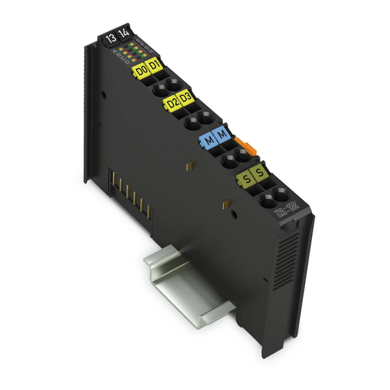
Device Description WAGO-I/O-SYSTEM 750 XTR 750-652/040-000 Serial Interface RS-232/RS-485 XTR View Figure 1: View Table 3: Legend for Figure “View” Pos. Description Details See Section Marking possibility with Mini- Status LEDs “Device Description” > “Display Elements” Data contacts “Device Description” > “Connectors”... -
Page 19: Connectors
WAGO-I/O-SYSTEM 750 XTR Device Description 750-652/040-000 Serial Interface RS-232/RS-485 XTR Connectors 3.2.1 Data Contacts/Local Bus Communication between the fieldbus coupler/controller and the I/O modules as well as the system supply of the I/O modules is carried out via the local bus. The contacting for the local bus consists of 6 data contacts, which are available as self- cleaning gold spring contacts. -
Page 20: Power Jumper Contacts/Field Supply
The blade contacts are sharp-edged. Handle the I/O module carefully to prevent injury. Do not touch the blade contacts. The I/O module 750-652/040-000 has 2 self-cleaning power jumper contacts that supply and transmit power for the field side. The contacts on the left side of the I/O module are designed as blade contacts and those on the right side as spring contacts. -
Page 21: Cage Clamp
I/O module can be achieved even in the presence of interference acting on the signal cable. For further information about shielding, see system manual WAGO-I/O-SYSTEM 750 XTR, section “Connect Devices” > … > “Shielding.”... -
Page 22: Display Elements
Device Description WAGO-I/O-SYSTEM 750 XTR 750-652/040-000 Serial Interface RS-232/RS-485 XTR Display Elements Figure 5: Display Elements Table 6: Legend for Figure “Display Elements” Designation Status Function Ready for operation and undisturbed Green local bus communication Function Not ready for operation or no or disturbed... -
Page 23: Operating Elements
XON/XOFF data flow control active RTS/CTS data flow control active Defective characters are not transmitted by the I/O module to the fieldbus coupler/controller. Operating Elements The I/O module 750-652/040-000 has no operating elements. Schematic Diagram Figure 6: Schematic Diagram Manual... -
Page 24: Technical Data
Device Description WAGO-I/O-SYSTEM 750 XTR 750-652/040-000 Serial Interface RS-232/RS-485 XTR Technical Data 3.6.1 Device Data Table 7: Technical Data – Device Width 12 mm Height (from upper edge of DIN-rail) 60.6 mm Depth 100 mm Weight 51 g Degree of protection IP20 3.6.2... -
Page 25: Communication
WAGO-I/O-SYSTEM 750 XTR Device Description 750-652/040-000 Serial Interface RS-232/RS-485 XTR 3.6.3 Communication Table 9: Technical Data – Communication Transmission 1 TxD/1 RxD, full-duplex, half-duplex, channels 7 or 8 bit data, 1 or 2 stop bits Mode • RS-232 (configurable) •... -
Page 26: Connection Type
Device Description WAGO-I/O-SYSTEM 750 XTR 750-652/040-000 Serial Interface RS-232/RS-485 XTR 3.6.5 Connection Type Table 11: Technical Data – Field Wiring ® Wire connection CAGE CLAMP Cross section 0.25 mm² … 2.5 mm² / AWG 24 … 14 Stripped lengths 8 mm … 9 mm / 0.33 in Table 12: Technical Data –... -
Page 27: Approvals
The following approvals have been granted to 750-652/040-000 I/O modules: Conformity Marking UL508 Korea Certification MSIP-REM-W43-SIM750 The following Ex approvals have been granted to 750-652/040-000 I/O modules: ANSI/ISA 12.12.01 Class I, Div2 ABCD T4 TÜV 17 ATEX 193969 X II 3 G Ex ec IIC T4 Gc IECEx TUN 16.0046X... -
Page 28: Standards And Guidelines
Device Description WAGO-I/O-SYSTEM 750 XTR 750-652/040-000 Serial Interface RS-232/RS-485 XTR Standards and Guidelines 750-652/040-000 I/O modules meet the following standards and guidelines: Table 16: Standards and Rated Conditions for Explosion Protection Applications ATEX acc. Directive 2014/34/EU General Requirements EN 60079-0:2012 + A11:2013... -
Page 29: Table 17: Climatic And Mechanical Environmental Conditions And
WAGO-I/O-SYSTEM 750 XTR Device Description 750-652/040-000 Serial Interface RS-232/RS-485 XTR Table 17: Climatic and Mechanical Environmental Conditions and Shipbuilding Standard Test Value Transport EN 60870-2-2 Ct2(2k4) (except precipitation/water/moisture) Mechanical Environmental Conditions EN 61850-3 Achieved EN 60870-2-2 EN 60721-3-1 EN 60721-3-3... -
Page 30: Table 18: Emc - Immunity To Interference
Device Description WAGO-I/O-SYSTEM 750 XTR 750-652/040-000 Serial Interface RS-232/RS-485 XTR The I/O module 750-652/040-000 meets the following EMC standards as these standards relate to the I/O module: Table 18: EMC – Immunity to Interference Standard Test Value Electrostatic Discharge • EN 61000-4-2 8 kV (contact discharge) •... - Page 31 WAGO-I/O-SYSTEM 750 XTR Device Description 750-652/040-000 Serial Interface RS-232/RS-485 XTR Table 18: EMC – Immunity to Interference Standard Test Value Line Frequency Disturbances • EN 60255-26 Standard not applicable Alternating Components of the Voltage to DC Line Connections • EN 61000-4-17 15 % •...
-
Page 32: Table 19: Emc - Emission Of Interference
Device Description WAGO-I/O-SYSTEM 750 XTR 750-652/040-000 Serial Interface RS-232/RS-485 XTR Table 19: EMC – Emission of Interference Standard Test Value Enclosure Emission of Interference • EN 61000-6-3 30 dB(µV/m), QP, 30 MHz … 230 MHz • EN 55022 Class B 37 dB(µV/m), QP, 230 MHz …... -
Page 33: Table 20: Standards And Rated Conditions For Rail Applications (En 50155)
EN 50121-3-2 5.5 EMC (Emission of Interference, EN 50121-3-2 Immunity to Interference) EN 50121-4 EN 50121-5 9.11 Materials (Fire Protection) EN 45545-2 Hazard level HL3 WAGO is a company certified in accordance with the IRIS quality standard. Manual Version 1.3.0... -
Page 34: Process Image
Process Image WAGO-I/O-SYSTEM 750 XTR 750-652/040-000 Serial Interface RS-232/RS-485 XTR Process Image Mapping of process data in the process image of fieldbus systems The representation of the I/O modules’ process data in the process image depends on the fieldbus coupler/controller used. Please take this information as well as the particular design of the respective control/status bytes from the section “Fieldbus Specific Design of the Process Data”... -
Page 35: Table 22: Control Byte C0
WAGO-I/O-SYSTEM 750 XTR Process Image 750-652/040-000 Serial Interface RS-232/RS-485 XTR The structure of the control and status bytes is described in the tables below. Table 22: Control Byte C0 Bit 7 Bit 6 Bit 5 Bit 4 Bit 3 Bit 2... -
Page 36: Data Exchange Mode
Process Image WAGO-I/O-SYSTEM 750 XTR 750-652/040-000 Serial Interface RS-232/RS-485 XTR Table 25: Status Byte S1 Bit 7 Bit 6 Bit 5 Bit 4 Bit 3 Bit 2 Bit 1 Bit 0 BUF_E Input length (number of characters received that are available in the input data, bit 3) -
Page 37: Table 27: Control Byte C0
WAGO-I/O-SYSTEM 750 XTR Process Image 750-652/040-000 Serial Interface RS-232/RS-485 XTR The structure of the control and status bytes is described in the tables below. Table 27: Control Byte C0 Bit 7 Bit 6 Bit 5 Bit 4 Bit 3 Bit 2... -
Page 38: Function Description
Function Description WAGO-I/O-SYSTEM 750 XTR 750-652/040-000 Serial Interface RS-232/RS-485 XTR Function Description In den Operating Modes for Serial Transmission In the operating modes for serial transmission, the I/O module allows communication with serial devices via RS-232, RS-485, RS-422 or DMX. -
Page 39: Receive Data
WAGO-I/O-SYSTEM 750 XTR Function Description 750-652/040-000 Serial Interface RS-232/RS-485 XTR If continuous transmission is activated, the I/O module evaluates the bit SC in control byte 0. Only when SC takes the value 1 does the I/O module transmit the data contained in the output buffer to the serial interface. The application can set SC to 0 to prompt the I/O module to accumulate data in the output buffer. -
Page 40: Rs-232 Operating Mode
Function Description WAGO-I/O-SYSTEM 750 XTR 750-652/040-000 Serial Interface RS-232/RS-485 XTR 5.1.3 RS-232 Operating Mode The RS-232 operating mode in full-duplex is realized in a 2-wire or 4-wire point-to- point connection. Simultaneous transmission and receiving is possible. In this mode, the I/O module supports flow control for the serial interface. The I/O... -
Page 41: Rs-485 Operating Mode
WAGO-I/O-SYSTEM 750 XTR Function Description 750-652/040-000 Serial Interface RS-232/RS-485 XTR 5.1.4 RS-485 Operating Mode The RS-485 operating mode in half-duplex is realized in a 2-wire multi-endpoint (bus) connection. Simultaneous transmission and receiving is not possible with 2-wire connections. The I/O module switches to receive mode after transmitting the content of the input buffer to the serial interface completely. -
Page 42: Receiving Data Packets In Dmx Mode
DMX packets can also be received in DMX mode with firmware version 06 or higher. In this mode, control commands can also be transmitted to a WAGO controller in systems in which DMX control is generated, for example, from a lighting control desk. -
Page 43: Figure 7: Internal Structure
WAGO-I/O-SYSTEM 750 XTR Function Description 750-652/040-000 Serial Interface RS-232/RS-485 XTR Figure 7: Internal Structure If two I/O modules are connected together in this mode, each I/O module transmits the data bytes of the process output image cyclically to the I/O module on the opposite side. -
Page 44: Mounting
750-652/040-000 Serial Interface RS-232/RS-485 XTR Mounting Mounting Sequence Fieldbus couplers, controllers and I/O modules of the WAGO-I/O-SYSTEM 750 are snapped directly on a carrier rail in accordance with the European standard EN 60175 (DIN 35). The reliable positioning and connection is made using a tongue and groove system. -
Page 45: Inserting And Removing Devices
WAGO-I/O-SYSTEM 750 XTR Mounting 750-652/040-000 Serial Interface RS-232/RS-485 XTR Inserting and Removing Devices Do not touch hot surfaces! The surface of the housing can become hot during operation. If the device was operated at high ambient temperatures, allow it to cool off before touching it. -
Page 46: Figure 9: Snap The I/O Module Into Place (Example)
Mounting WAGO-I/O-SYSTEM 750 XTR 750-652/040-000 Serial Interface RS-232/RS-485 XTR Press the I/O module into the assembly until the I/O module snaps into the carrier rail. Figure 9: Snap the I/O Module into Place (Example) With the I/O module snapped in place, the electrical connections for the data contacts and power jumper contacts (if any) to the fieldbus coupler/controller or to the previous or possibly subsequent I/O module are established. -
Page 47: Removing The I/O Module
WAGO-I/O-SYSTEM 750 XTR Mounting 750-652/040-000 Serial Interface RS-232/RS-485 XTR 6.2.2 Removing the I/O Module Remove the I/O module from the assembly by pulling the release tab. Figure 10: Removing the I/O Module (Example) Electrical connections for data or power jumper contacts are disconnected when removing the I/O module. -
Page 48: Connect Devices
Only one conductor may be connected to each CAGE CLAMP Do not connect more than one conductor at one single connection! If more than one conductor must be routed to one connection, these must be connected in an up-circuit wiring assembly, for example using WAGO feed-through terminals. ®... -
Page 49: Connection Examples
WAGO-I/O-SYSTEM 750 XTR Connect Devices 750-652/040-000 Serial Interface RS-232/RS-485 XTR Connection Examples 7.2.1 RS-232 Operating Mode Figure 12: Point-to-point Connection Operating Mode RS-232 with RTS/CTS Data Flow Control In the RS-232 operating mode (point-to-point connection), terminal resistors are not necessary. -
Page 50: Rs-422 Operating Mode
If the 750-652/040-000 serial interface module works on a network with other communication partners, the wiring of a resistance-biasing network (known as a fail-safe network) to one line end can be necessary. -
Page 51: Rs-485 Operating Mode
(idle line). If the 750-652/040-000 serial interface module works on a network with other communication partners, the wiring of a resistance-biasing network (known as a fail-safe network) to one line end can be necessary. -
Page 52: Dmx Operating Mode
Connect Devices WAGO-I/O-SYSTEM 750 XTR 750-652/040-000 Serial Interface RS-232/RS-485 XTR Figure 15: Bus Connection RS-485 Operating Mode with Biasing Network, Half-Duplex With the use of the biasing resistors, it is guaranteed in this case that all receiver inputs A have the voltage difference of more than 200 mV to the inputs B if no transmitter is active. -
Page 53: Data Exchange Mode
WAGO-I/O-SYSTEM 750 XTR Connect Devices 750-652/040-000 Serial Interface RS-232/RS-485 XTR 7.2.5 Data Exchange Mode Figure 16: Point-to-point Connection Between 2 Nodes In this mode, the contacts of the I/O modules to connect are connected to each other crosswise. In the Data Exchange operating mode (point-to-point connection), a twisted-pair cable should be used at least for larger cable lengths. -
Page 54: Commissioning
750-652/040-000 Serial Interface RS-232/RS-485 XTR Commissioning Configuration and Parameterization with WAGO-I/O-CHECK The serial interface module is configured with the WAGO-I/O-CHECK software. The software's basic functionality is described separately in the WAGO-I/O- CHECK documentation. Component damage due to incorrect voltage level! -
Page 55: Toolbar On The Configuration Dialog
I/O module. Opens a file with saved parameters. WAGO-I/O- Open CHECK shows the Open File dialog. Saves the current parameters in a file. WAGO-I/O- Save CHECK shows the Save File dialog. Reads the current settings from the connected I/O Read module. -
Page 56: Process Image Size
Commissioning WAGO-I/O-SYSTEM 750 XTR 750-652/040-000 Serial Interface RS-232/RS-485 XTR 8.1.3 Process Image Size To make settings on the “PI Mapping” (process image mapping) page, the process image size of the master must be set first. Use the [Configuration] button on the toolbar to open the dialog for entering the process image size. -
Page 57: Parameter Range
WAGO-I/O-SYSTEM 750 XTR Commissioning 750-652/040-000 Serial Interface RS-232/RS-485 XTR 8.1.4 Parameter Range Figure 20: Parameter range The following selection boxes are displayed in tabular form. The possible settings are described in more detail in the chapter “Function Description”. Table 31: Parameter Range... -
Page 58: Setting The Rs-232/Rs-485 Serial Interface
• Flow control: RTS with lead/follow-on time • DMX start channel number These values can be changed in WAGO-I/O-CHECK. 8.1.5 Setting the RS-232/RS-485 Serial Interface Open the configuration dialog for the serial interface module by selecting Settings in the context menu of the I/O module (node view or navigation). -
Page 59: Configuration And Parameterization Via Gsd File With Profibus Dp And Profinet Io
WAGO-I/O-SYSTEM 750 XTR Commissioning 750-652/040-000 Serial Interface RS-232/RS-485 XTR You can also put the I/O module into another operating mode. Here the changed configuration is saved and the inputs and outputs of the I/O module are switched immediately according to the operating mode. -
Page 60: Initialization
Commissioning WAGO-I/O-SYSTEM 750 XTR 750-652/040-000 Serial Interface RS-232/RS-485 XTR • Inversion and output of RA • Reading out has taken place when RR = RA The transmission and receipt of data between controller and I/O module can take place simultaneously. The initialization request is executed with priority and immediately ends the transmission and receipt of data. -
Page 61: Transmission Of The Character String "Hello World
WAGO-I/O-SYSTEM 750 XTR Commissioning 750-652/040-000 Serial Interface RS-232/RS-485 XTR 8.3.3 Transmission of the Character String "Hello World!" The 11 characters, the reset initialization bit, and the length 11 are transmitted. Table 36: Character String "Hello World" Control byte 0 Control byte 1... -
Page 62: Operation With Continuous Send
Commissioning WAGO-I/O-SYSTEM 750 XTR 750-652/040-000 Serial Interface RS-232/RS-485 XTR Table 40: Receive Data Status byte 0 Status byte 1 Input byte 0 Input byte 1 0-xxx X (00x) '0XXX. 1XXX' There are no receive data available. '0XX1. 001X' '0XXX. 1XXX' "W"... -
Page 63: Transmission Of A Block Of More Than 512 Bytes
WAGO-I/O-SYSTEM 750 XTR Commissioning 750-652/040-000 Serial Interface RS-232/RS-485 XTR Table 44: Transmission of a Block of 1 to 512 Bytes Control byte 0 Control byte 1 '0110.1001' '0XXX. X101' Controller fills the output buffer with 46 bytes and set bit 3 (SC) of the control byte 0 for the start of the transmission. -
Page 64: Table 45: Transmission Of A Block Of More Than 512 Bytes
Commissioning WAGO-I/O-SYSTEM 750 XTR 750-652/040-000 Serial Interface RS-232/RS-485 XTR Table 45: Transmission of a Block of More Than 512 Bytes Control byte 0 Control byte 1 '0110.1001' '0XXX. X101' Controller fills the output buffer with 46 bytes and set bit 3 (SC) of the control byte 0 for the start of the transmission. -
Page 65: Dmx Application Example
WAGO-I/O-SYSTEM 750 XTR Commissioning 750-652/040-000 Serial Interface RS-232/RS-485 XTR 8.3.6 DMX Application Example 8.3.6.1 Operation with Deactivated Continuous Send In this mode, the I/O module only transmits the data for a limited number of DMX channels according to the set size of the process image (see table “Process data in the DMX operating mode without continuous send”). -
Page 66: Mode When Receiving Dmx Data
Commissioning WAGO-I/O-SYSTEM 750 XTR 750-652/040-000 Serial Interface RS-232/RS-485 XTR Malfunctions possible under high load conditions! If there are a large number of I/O modules in the node or if transmitting via multiple DMX channels, the refresh rate can drop below 1 update per second. -
Page 67: 8.3.6.3.1 "Dmx Receive" Operating Parameters
• Node configuration: Position 00: 750-881 [Version: SW 01.05.15(07) / HW 07 / FWL 03] Position 01: 750-652/040-000 [Version: SW 01.02.15(06) / HW 01] Process image size: 48 Bytes Position 02: 750-652/040-000 [Version: SW 01.02.15(06) / HW 01] Process image size: 24 Bytes Manual Version 1.3.0... -
Page 68: 8.3.6.3.2 "Dmx Receive" Application Example
Commissioning WAGO-I/O-SYSTEM 750 XTR 750-652/040-000 Serial Interface RS-232/RS-485 XTR 8.3.6.3.2 “DMX Receive” Application Example This subsection describes 2 application examples. The application examples always have a process image of 24 bytes. Example 1 Setting: A DMX channel with number 1 as the start channel and a process image size of 24 bytes is set. -
Page 69: Figure 21: Example Assignment Of Dmx Channels To The Input Process
WAGO-I/O-SYSTEM 750 XTR Commissioning 750-652/040-000 Serial Interface RS-232/RS-485 XTR Figure 21: Example Assignment of DMX Channels to the Input Process Image Manual Version 1.3.0... -
Page 70: Data Exchange Operating Mode Application Example
Commissioning WAGO-I/O-SYSTEM 750 XTR 750-652/040-000 Serial Interface RS-232/RS-485 XTR 8.3.7 Data Exchange Operating Mode Application Example In the “Data Exchange” operating mode, the I/O module monitors process data exchange with the partner module. If the connection is interrupted for 200 ms or more, it generates a diagnosis in the status byte. -
Page 71: Diagnostics
WAGO-I/O-SYSTEM 750 XTR Diagnostics 750-652/040-000 Serial Interface RS-232/RS-485 XTR Diagnostics Serial Operating Modes RS-232, RS-422 and RS-485 Table 50: Diagnostics, Serial Operating Modes RS-232, RS-422 and RS-485 Diagnostics Event Solution Input buffer full The I/O module receives • Make sure that the application... -
Page 72: Data Exchange Operating Mode
Diagnostics WAGO-I/O-SYSTEM 750 XTR 750-652/040-000 Serial Interface RS-232/RS-485 XTR Data Exchange Operating Mode Table 52: Diagnostics, Data Exchange Diagnostics Event Solution Wrong length The I/O modules have • Configure the same process different process image image size sizes Checksum error Data transmission was •... -
Page 73: Use In Hazardous Environments
Use in Hazardous Environments 750-652/040-000 Serial Interface RS-232/RS-485 XTR Use in Hazardous Environments The WAGO-I/O-SYSTEM 750 (electrical equipment) is designed for use in Zone 2 hazardous areas and shall be used in accordance with the marking and installation regulations. The following sections include both the general identification of components (devices) and the installation regulations to be observed. -
Page 74: Marking Configuration Examples
Use in Hazardous Environments WAGO-I/O-SYSTEM 750 XTR 750-652/040-000 Serial Interface RS-232/RS-485 XTR 10.1 Marking Configuration Examples 10.1.1 Marking for Europe According to ATEX and IECEx Figure 22: Marking Example According to ATEX and IECEx Figure 23: Text Detail – Marking Example According to ATEX and IECEx Manual Version 1.3.0... -
Page 75: Table 53: Description Of Marking Example According To Atex And Iecex
WAGO-I/O-SYSTEM 750 XTR Use in Hazardous Environments 750-652/040-000 Serial Interface RS-232/RS-485 XTR Table 53: Description of Marking Example According to ATEX and IECEx Marking Description TUEV 07 ATEX 554086 X Approving authority resp. certificate numbers IECEx TUN 09.0001 X Dust... -
Page 76: Figure 24: Marking Example For Approved Ex I I/O Module According To
Use in Hazardous Environments WAGO-I/O-SYSTEM 750 XTR 750-652/040-000 Serial Interface RS-232/RS-485 XTR Figure 24: Marking Example for Approved Ex i I/O Module According to ATEX and IECEx Figure 25: Text Detail – Marking Example for Approved Ex i I/O Module According to ATEX and... -
Page 77: Table 54: Description Of Marking Example For Approved Ex I I/O Module According To Atex And Iecex
WAGO-I/O-SYSTEM 750 XTR Use in Hazardous Environments 750-652/040-000 Serial Interface RS-232/RS-485 XTR Table 54: Description of Marking Example for Approved Ex i I/O Module According to ATEX and IECEx Marking Description TUEV 12 ATEX 106032 X Approving authority resp. certificate numbers... -
Page 78: Marking For The United States Of America (Nec) And Canada (Cec)
Use in Hazardous Environments WAGO-I/O-SYSTEM 750 XTR 750-652/040-000 Serial Interface RS-232/RS-485 XTR 10.1.2 Marking for the United States of America (NEC) and Canada (CEC) Figure 26: Marking Example According to NEC Figure 27: Text Detail – Marking Example According to NEC 500... -
Page 79: Figure 28: Text Detail - Marking Example For Approved Ex I I/O Module
WAGO-I/O-SYSTEM 750 XTR Use in Hazardous Environments 750-652/040-000 Serial Interface RS-232/RS-485 XTR Figure 28: Text Detail – Marking Example for Approved Ex i I/O Module According to NEC 505 Table 56: Description of Marking Example for Approved Ex i I/O Module According to NEC 505... -
Page 80: Figure 30: Text Detail - Marking Example For Approved Ex I I/O Modules
Use in Hazardous Environments WAGO-I/O-SYSTEM 750 XTR 750-652/040-000 Serial Interface RS-232/RS-485 XTR Figure 30: Text Detail – Marking Example for Approved Ex i I/O Modules According to CEC 18 attachment J Table 58: Description of Marking Example for Approved Ex i I/O Modules According to CEC 18... -
Page 81: Installation Regulations
WAGO-I/O-SYSTEM 750 XTR Use in Hazardous Environments 750-652/040-000 Serial Interface RS-232/RS-485 XTR 10.2 Installation Regulations For the installation and operation of electrical equipment in hazardous areas, the valid national and international rules and regulations which are applicable at the installation location must be carefully followed. - Page 82 Use in Hazardous Environments WAGO-I/O-SYSTEM 750 XTR 750-652/040-000 Serial Interface RS-232/RS-485 XTR Explosive atmosphere occurring simultaneously with assembly, installation or repair work must be ruled out. Among other things, these include the following activities • Insertion and removal of components •...
-
Page 83: Special Notes Regarding Ansi/Isa Ex
WAGO-I/O-SYSTEM 750 XTR Use in Hazardous Environments 750-652/040-000 Serial Interface RS-232/RS-485 XTR 10.2.2 Special Notes Regarding ANSI/ISA Ex For ANSI/ISA Ex acc. to UL File E198726, the following additional requirements apply: • Use in Class I, Division 2, Group A, B, C, D or non-hazardous areas only •... -
Page 84: Appendix
Appendix WAGO-I/O-SYSTEM 750 XTR 750-652/040-000 Serial Interface RS-232/RS-485 XTR Appendix 11.1 Configuration and Parameterization via GSD-File 11.1.1 Configuration of the RS-232/RS-485 Serial Interface When using the aforementioned PROFIBUS-DP fieldbus coupler 750-333/040-000, the process image size is configured by selecting the corresponding PI module type. -
Page 85: All Profibus Dp Fieldbus Couplers
Make sure that devices you connect support the voltage level of the current operating mode! The following assignment applies to the parameters of the I/O module when using PROFIBUS-DP fieldbus couplers: Table 60: Specific Module / Channel Parameters for 750-652/040-000 GSD File WAGO-I/O-CHECK Description... -
Page 86: Profibus Dp Fieldbus Coupler (750-333/040-000)
Appendix WAGO-I/O-SYSTEM 750 XTR 750-652/040-000 Serial Interface RS-232/RS-485 XTR Table 60: Specific Module / Channel Parameters for 750-652/040-000 GSD File WAGO-I/O-CHECK Description Value Selection box Value Parity none Parity none Parity straight Parity straight Stop bits Stop Bits Stop Bits... -
Page 87: List Of Figures
WAGO-I/O-SYSTEM 750 XTR List of Figures 750-652/040-000 Serial Interface RS-232/RS-485 XTR List of Figures Figure 1: View ....................18 Figure 2: Data Contacts ..................19 Figure 3: Power Jumper Contacts ..............20 ® Figure 4: CAGE CLAMP Connectors ..............21 Figure 5: Display Elements.................22 Figure 6: Schematic Diagram ................23... -
Page 88: List Of Tables
List of Tables WAGO-I/O-SYSTEM 750 XTR 750-652/040-000 Serial Interface RS-232/RS-485 XTR List of Tables Table 1: Number Notation ................... 8 Table 2: Font Conventions .................. 8 Table 3: Legend for Figure “View” ..............18 Table 4: Legend for Figure “Power Jumper Contacts” ........20 ®... - Page 89 Table 58: Description of Marking Example for Approved Ex i I/O Modules According to CEC 18 attachment J ............80 Table 59: Configuration ..................84 Table 60: Specific Module / Channel Parameters for 750-652/040-000 ....85 Table 61: General Module / Channel Parameters ..........86 Manual...
- Page 90 WAGO Kontakttechnik GmbH & Co. KG Postfach 2880 • D - 32385 Minden Hansastraße 27 • D - 32423 Minden Phone: +49 571 887 – 0 Fax: +49 571 887 – 844169 E-Mail: info@wago.com Internet: www.wago.com...
Need help?
Do you have a question about the 750-652/040-000 and is the answer not in the manual?
Questions and answers