Table of Contents
Advertisement
Quick Links
Pos: 2 /Dokumentation allgemein/Einband/Einband Handbuch - Frontseite 2015 - mit DocVariablen (Standard) @ 9\mod_1285229289866_0.docx @ 64941 @ @ 1
WAGO-I/O-SYSTEM 750
750-666/000-003
4FDI/2FDO 24V/10A PROFIsafe V2 iPar
4-Channel Digital Input and 2-Channel Digital
Output Module PROFIsafe V2 iPar,
24V/10A semiconductor power output
Version 1.4.0, valid from
HW/SW Version 01/01
Pos: 3 /Alle Serien (Allgemeine Module)/Hinweise zur Dokumentation/Impressum für Standardhandbücher - allg. Angaben, Anschriften, Telefonnummern und E-Mail-Adressen @ 3\mod_1219151118203_21.docx @ 21060 @ @ 1
Advertisement
Chapters
Table of Contents

Related Manuals for WAGO I/O-SYSTEM 750-666/000-003


Summary of Contents for WAGO I/O-SYSTEM 750-666/000-003
- Page 1 Pos: 2 /Dokumentation allgemein/Einband/Einband Handbuch - Frontseite 2015 - mit DocVariablen (Standard) @ 9\mod_1285229289866_0.docx @ 64941 @ @ 1 WAGO-I/O-SYSTEM 750 Manual 750-666/000-003 4FDI/2FDO 24V/10A PROFIsafe V2 iPar 4-Channel Digital Input and 2-Channel Digital Output Module PROFIsafe V2 iPar, 24V/10A semiconductor power output Version 1.4.0, valid from...
- Page 2 WAGO-I/O-SYSTEM 750 750-666/000-003 4FDI/2FDO 24V/10A PROFIsafe V2 iPar © 2015 by WAGO Kontakttechnik GmbH & Co. KG All rights reserved. WAGO Kontakttechnik GmbH & Co. KG Hansastraße 27 D-32423 Minden Phone: +49 (0) 571/8 87 – 0 Fax: +49 (0) 571/8 87 – 1 69 E-Mail: info@wago.com...
-
Page 3: Table Of Contents
2.1.1 Subject to Changes ................12 2.1.2 Personnel Qualifications ..............12 2.1.3 Use of the WAGO-I/O-SYSTEM 750 in Compliance with Underlying Provisions ................ 12 2.1.4 Technical Condition of Specified Devices ......... 13 Safety Advice (Precautions) ..............14 PROFIsafe ....................16 iPar Server .................... - Page 4 7.3.3.3 Output Configuration H-Side/H-Side 1 ......... 77 7.3.3.4 Output Configuration H-Side/H-Side 2 ......... 79 7.3.3.5 Switching I/O Modules of the WAGO-I/O-SYSTEM 750 ... 81 7.3.3.5.1 Using Output Configuration H-Side/L-Side 1 ......82 7.3.3.5.2 Using Output Configuration H-Side/H-Side 1 ......85 7.3.3.6...
- Page 5 Setting the PROFIsafe Address using the Coding Switch ....97 8.2.2 Setting the PROFIsafe Address using the WAGO Parameterization Tool..................... 98 Parameterization of the PROFIsafe I/O Module with the WAGO Parameterization Tool ................99 8.3.1 ONLINE Mode ................. 100 8.3.2 OFFLINE Mode ................
- Page 6 Table of Contents WAGO-I/O-SYSTEM 750 750-666/000-003 4FDI/2FDO 24V/10A PROFIsafe V2 iPar Diagnostics ....................132 Behavior in the Event of an Error ............132 Diagnosis of Errors ................133 Acknowledging Error Messages ............140 9.3.1 Variant 1: User Acknowledgement via “OA_Req” ......141 9.3.2...
-
Page 7: Notes About This Documentation
Pos: 12 /Alle Serien (Allgemeine Module)/Hinweise zur Dokumentation/Gültigkeitsbereich Dokumentation Ergänzung "ab <FW/HW/SW-Version>" @ 20\mod_1407749774742_21.docx @ 161508 @ @ 1 This documentation is only applicable from HW/SW Version 01/01. Pos: 13 /Serie 750 (WAGO-I/O-SYSTEM)/Hinweise zur Dokumentation/Hinweise/Achtung: Hinweis zur Dokumentation Busklemmen 750-xxxx @ 4\mod_1237986979656_21.docx @ 29023 @ @ 1 The I/O module 750-666/000-003 shall only be installed and operated according to the instructions in this manual and in the manual for the used fieldbus coupler/controller. - Page 8 Notes about this Documentation WAGO-I/O-SYSTEM 750 750-666/000-003 4FDI/2FDO 24V/10A PROFIsafe V2 iPar written consent of WAGO Kontakttechnik GmbH & Co. KG, Minden, Germany. Non-observance will involve the right to assert damage claims. Pos: 15.2 /Dokumentation allgemein/Gliederungselemente/---Seitenwechsel--- @ 3\mod_1221108045078_0.docx @ 21810 @ @ 1 Manual Version 1.4.0, valid from HW/SW Version 01/01...
-
Page 9: Symbols
WAGO-I/O-SYSTEM 750 Notes about this Documentation 750-666/000-003 4FDI/2FDO 24V/10A PROFIsafe V2 iPar Pos: 15.3 /Alle Serien (Allgemeine Module)/Überschriften für alle Serien/Hinweise zur Dokumentation/Symbole - Überschrift 2 @ 13\mod_1351068042408_21.docx @ 105270 @ 2 @ 1 Symbols Pos: 15.4.1 /Alle Serien (Allgemeine Module)/Wichtige Erläuterungen/Sicherheits- und sonstige Hinweise/Gefahr/Gefahr: _Warnung vor Personenschäden allgemein_ - Erläuterung @ 13\mod_1343309450020_21.docx @ 101029 @ @ 1... - Page 10 Notes about this Documentation WAGO-I/O-SYSTEM 750 750-666/000-003 4FDI/2FDO 24V/10A PROFIsafe V2 iPar Additional Information: Refers to additional information which is not an integral part of this documentation (e.g., the Internet). Pos: 15.5 /Dokumentation allgemein/Gliederungselemente/---Seitenwechsel--- @ 3\mod_1221108045078_0.docx @ 21810 @ @ 1 Manual Version 1.4.0, valid from HW/SW Version 01/01...
-
Page 11: Number Notation
Font Conventions Table 2: Font Conventions Font Type Indicates italic Names of paths and data files are marked in italic-type. e.g.: C:\Program Files\WAGO Software Menu Menu items are marked in bold letters. e.g.: Save > A greater-than sign between two names means the selection of a menu item from a menu. -
Page 12: Important Notes
PLC programming. Pos: 18.5 /Serie 750 (WAGO-I/O-SYSTEM)/Wichtige Erläuterungen/Sicherheits- und sonstige Hinweise/Gefahr/Gefahr: Austausch von PROFIsafe-Busklemmen nur durch sicherheitstechnisch sachkundige Personen @ 4\mod_1239786227890_21.docx @ 30470 @ @ 1 Only personnel trained in safety-related procedures may perform the work! -
Page 13: Technical Condition Of Specified Devices
“Device Description” > “Standards and Guidelines” in the manual for the used fieldbus coupler/controller. Appropriate housing (per 94/9/EG) is required when operating the WAGO-I/O- SYSTEM 750 in hazardous environments. Please note that a prototype test certificate must be obtained that confirms the correct installation of the system in a housing or switch cabinet. -
Page 14: Safety Advice (Precautions)
Pos: 18.11.2 /Serie 750 (WAGO-I/O-SYSTEM)/Wichtige Erläuterungen/Sicherheits- und sonstige Hinweise/Gefahr/Gefahr: Einbau 0750-xxxx nur in Gehäusen, Schränken oder elektrischen Betriebsräumen! @ 6\mod_1260180556692_21.docx @ 46731 @ @ 1 Install the device only in appropriate housings, cabinets or in electrical operation rooms! The WAGO-I/O-SYSTEM 750 and its components are an open system. - Page 15 WAGO-I/O-SYSTEM 750 Important Notes 750-666/000-003 4FDI/2FDO 24V/10A PROFIsafe V2 iPar Clean only with permitted materials! Clean soiled contacts using oil-free compressed air or with ethyl alcohol and leather cloths. Pos: 18.13.4 /Alle Serien (Allgemeine Dokumente) (Allgemeine Module)/Wichtige Erläuterungen/Sicherheitshinweise/Achtung/Achtung: Kein Kontaktspray verwenden! @ 6\mod_1260181290808_21.docx @ 46755 @ @ 1 Do not use any contact spray! Do not use any contact spray.
-
Page 16: Profisafe
PROFIsafe WAGO-I/O-SYSTEM 750 750-666/000-003 4FDI/2FDO 24V/10A PROFIsafe V2 iPar Pos: 20 /Serie 750 (WAGO-I/O-SYSTEM)/Systembeschreibung/PROFIsafe Allgemeine Beschreibung @ 4\mod_1235470712968_21.docx @ 27651 @ 1 @ 1 PROFIsafe PROFIsafe is a protocol for secure communication, and is certified in accordance with IEC 61784-3-3. -
Page 17: Figure 2: Profisafe Layer Model
Safety (PROFsafe Environmental Requirements, current version) • Installation recommendations (Handbook PROFIBUS Installation Guideline, current version) These documents are available on the Internet at http://www.profibus.com/ Pos: 21 /Serie 750 (WAGO-I/O-SYSTEM)/Systembeschreibung/iPar-Server @ 7\mod_1268385000661_21.docx @ 52430 @ 2 @ 1 Manual Version 1.4.0, valid from HW/SW Version 01/01... -
Page 18: Ipar Server
The iPar parameters are used to configure device functions of a safe device such as the PROFIsafe I/O modules of the WAGO-I/O-SYSTEM 750/753. The “WAGO Safety Editor 75x” parameterization tool (SEDI) can be used to set the individual parameters of WAGO PROFIsafe I/O modules. SEDI is the CPD tool for WAGO PROFIsafe I/O modules. - Page 19 PLC. Further details about using the iPar server in conjunction with the WAGO PROFIsafe I/O modules are available in an application note. Use the application notes from WAGO! An overview for using the PROFIsafe I/O module in combination with a safe PLC is summarized in an application note.
-
Page 20: Device Description
Pos: 23 /Alle Serien (Allgemeine Module)/Überschriften für alle Serien/Gerätebeschreibung/Gerätebeschreibung - Überschrift 1 @ 3\mod_1233756084656_21.docx @ 27096 @ 1 @ 1 Device Description Pos: 24.1.1 /Serie 750 (WAGO-I/O-SYSTEM)/Gerätebeschreibung/Einleitung/Anwendung/SO/Anwendung 750-066x/000-003 PROFIsafe Einleitung, mit DIN EN 61511:2004, SIL3 @ 12\mod_1340690521168_21.docx @ 98334 @ @ 1 </dg_... - Page 21 Pos: 24.1.7 /Serie 750 (WAGO-I/O-SYSTEM)/Gerätebeschreibung/Einleitung/LED-Anzeige/Verweis auf Kapitel "Anzeigeelemente" @ 5\mod_1246010525000_21.docx @ 36194 @ @ 1 The meaning of the LEDs is described in the “Display Elements” section. Pos: 24.1.8 /Serie 750 (WAGO-I/O-SYSTEM)/Wichtige Erläuterungen/Sicherheits- und sonstige Hinweise/Hinweis/Hinweis: PROFIsafe Einspeisekonzept beachten @ 7\mod_1265283290674_21.docx @ 49728 @ @ 1 Observe the information on the power supply concept! Detailed information and examples for supplying PROFIsafe I/O modules is available in the section “Connecting Devices”...
-
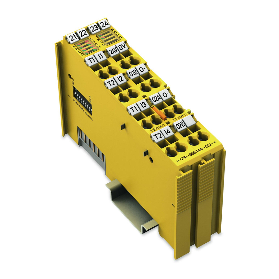
Page 22: View
Pos: 24.4 /Serie 750 (WAGO-I/O-SYSTEM)/Gerätebeschreibung/Ansicht/Sonderklemmen/Ansicht 750-0666/000-003 - Abb. @ 7\mod_1273655741299_21.docx @ 56450 @ @ 1 Figure 4: View Pos: 24.5 /Serie 750 (WAGO-I/O-SYSTEM)/Gerätebeschreibung/Ansicht/Ansicht CageClamp®_Legende mit LEDs, mit 1 Entriegelungslasche @ 15\mod_1370867188922_21.docx @ 122225 @ @ 1 Table 4: Legend for Figure “View”... -
Page 23: Connectors
Do not place the I/O modules on the gold spring contacts in order to avoid soiling or scratching! Pos: 24.9.3 /Serie 750 (WAGO-I/O-SYSTEM)/Wichtige Erläuterungen/Sicherheits- und sonstige Hinweise/Achtung/Achtung: ESD - Auf gute Erdung der Umgebung achten! @ 7\mod_1266318538667_21.docx @ 50708 @ @ 1 Ensure that the environment is well grounded! The devices are equipped with electronic components that may be destroyed by electrostatic discharge. -
Page 24: Power Jumper Contacts/Field Supply
When configuring your system, ensure that this current is not exceeded. If exceeded, insert an additional supply module. Pos: 24.12.6 /Serie 750 (WAGO-I/O-SYSTEM)/Wichtige Erläuterungen/Sicherheits- und sonstige Hinweise/Hinweis/Hinweis: Potentialeinspeiseklemme für Erde einsetzen! (keine LK für Erde) @ 3\mod_1226499037468_21.docx @ 25023 @ @ 1 Manual... - Page 25 Use a supply module when an earth potential is needed for the subsequent I/O modules. Pos: 24.13 /Serie 750 (WAGO-I/O-SYSTEM)/Wichtige Erläuterungen/Sicherheits- und sonstige Hinweise/Hinweis/Hinweis: PROFIsafe Einspeisekonzept beachten @ 7\mod_1265283290674_21.docx @ 49728 @ @ 1 Observe the information on the power supply concept! Detailed information and examples for supplying PROFIsafe I/O modules is available in the section “Connecting Devices”...
-
Page 26: Cage Clamp ® Connectors
Device Description WAGO-I/O-SYSTEM 750 750-666/000-003 4FDI/2FDO 24V/10A PROFIsafe V2 iPar Pos: 24.15 /Serie 750 (WAGO-I/O-SYSTEM)/Gerätebeschreibung/Anschlüsse/CAGE CLAMP-Anschlüsse - Überschrift 3 @ 6\mod_1256296337770_21.docx @ 43674 @ 3 @ 1 ® 4.2.3 CAGE CLAMP Connectors Pos: 24.16 /Serie 750 (WAGO-I/O-SYSTEM)/Gerätebeschreibung/Anschlüsse/Sonderklemmen/Anschlüsse CC 750-0666/000-003 @ 7\mod_1273655765471_21.docx @ 56454 @ @ 1 ®... -
Page 27: Display Elements
Pos: 24.18 /Alle Serien (Allgemeine Module)/Überschriften für alle Serien/Gerätebeschreibung/Anzeigeelemente - Überschrift 2 @ 4\mod_1240984390875_21.docx @ 31964 @ 2 @ 1 Display Elements Pos: 24.19 /Serie 750 (WAGO-I/O-SYSTEM)/Gerätebeschreibung/Anzeigeelemente/Sonderklemmen/Anzeigeelemente 750-066x Eingänge 1 - 4 @ 7\mod_1273654138286_21.docx @ 56444 @ @ 1 Figure 8: Display Elements, Inputs 1 ... 4 Table 7: Legend for Figure “Display Elements, Inputs 1 ... -
Page 28: Figure 9: Display Elements, Outputs 1
WAGO-I/O-SYSTEM 750 750-666/000-003 4FDI/2FDO 24V/10A PROFIsafe V2 iPar Pos: 24.21 /Serie 750 (WAGO-I/O-SYSTEM)/Gerätebeschreibung/Anzeigeelemente/Sonderklemmen/Anzeigeelemente 750-0666 Ausgänge I-K @ 7\mod_1273654136989_21.docx @ 56436 @ @ 1 Figure 9: Display Elements, Outputs 1 … 2 Table 8: Legend for Figure “Display Elements, Outputs 1 … 2”... -
Page 29: Figure 10: Display Elements, Communication / I/O Module Status
Device Description 750-666/000-003 4FDI/2FDO 24V/10A PROFIsafe V2 iPar Pos: 24.23 /Serie 750 (WAGO-I/O-SYSTEM)/Gerätebeschreibung/Anzeigeelemente/Sonderklemmen/Anzeigeelemente 750-0666 Kommunikation E-H @ 10\mod_1306316500446_21.docx @ 73120 @ @ 1 Figure 10: Display Elements, Communication / I/O Module Status Table 9: Legend for Figure “Display Elements, Communication / I/O Module Status”... - Page 30 PROFIsafe I/O module completely and the switch it back on. If the problem occurs several times, it points to a defect in the PROFIsafe I/O module. In this case, return the PROFIsafe I/O module to WAGO Kontakttechnik GmbH & Co. KG for fault analysis.
-
Page 31: Operating Elements
Pos: 24.25 /Alle Serien (Allgemeine Module)/Überschriften für alle Serien/Gerätebeschreibung/Bedienelemente - Überschrift 2 @ 4\mod_1239191655456_21.docx @ 30439 @ 2 @ 1 Operating Elements Pos: 24.26 /Serie 750 (WAGO-I/O-SYSTEM)/Gerätebeschreibung/Bedienelemente/Busklemmen/Bedienelemente 75x-066x/000-003 @ 7\mod_1265287420132_21.docx @ 49740 @ @ 1 You can use the coding switch located on the side of the PROFIsafe I/O module to set the PROFIsafe address. -
Page 32: Schematic Diagrams
Pos: 24.29 /Serie 750 (WAGO-I/O-SYSTEM)/Gerätebeschreibung/Schematische Schaltbilder/Sonderklemmen/Schematisches Schaltbild 750-0666 @ 7\mod_1273554150130_21.docx @ 56325 @ @ 1 Figure 12: Schematic Diagram Pos: 24.30 /Serie 750 (WAGO-I/O-SYSTEM)/Gerätebeschreibung/Schematische Schaltbilder/Sonderklemmen/Prinzipschaltbild 75x-066x/000-003 PROFIsafe-Eingang @ 7\mod_1265287782311_21.docx @ 49762 @ 3 @ 1 Manual Version 1.4.0, valid from HW/SW Version 01/01... -
Page 33: Input Block Diagram
750-666/000-003 4FDI/2FDO 24V/10A PROFIsafe V2 iPar 4.5.1 Input Block Diagram Figure 13: Input Block Diagram Pos: 24.31 /Serie 750 (WAGO-I/O-SYSTEM)/Gerätebeschreibung/Schematische Schaltbilder/Sonderklemmen/Prinzipschaltbild 75x-0666/000-003 PROFIsafe-Ausgang @ 7\mod_1274952858352_21.docx @ 57100 @ 3 @ 1 4.5.2 Output Block Diagram Figure 14: Output Block Diagram Pos: 24.32 /Dokumentation allgemein/Gliederungselemente/---Seitenwechsel--- @ 3\mod_1221108045078_0.docx @ 21810 @ @ 1... -
Page 34: Technical Data
Pos: 24.33 /Alle Serien (Allgemeine Module)/Überschriften für alle Serien/Gerätebeschreibung/Technische Daten - Überschrift 2 @ 3\mod_1232967587687_21.docx @ 26924 @ 2 @ 1 Technical Data Pos: 24.34 /Serie 750 (WAGO-I/O-SYSTEM)/Gerätebeschreibung/Technische Daten/Sonderklemmen/Technische Daten 75x-0666/000-003 @ 7\mod_1273554237465_21.docx @ 56329 @ 333333 @ 1 4.6.1... -
Page 35: Communication
WAGO-I/O-SYSTEM 750 Device Description 750-666/000-003 4FDI/2FDO 24V/10A PROFIsafe V2 iPar 4.6.3 Communication Table 12: Technical Data, Communication 750-333 SW 14, HW 16 or higher 750-370 SW 02, HW 01 or higher Usable fieldbus couplers / controllers 750-375 SW 02, HW 01 or higher... -
Page 36: Digital Inputs
Device Description WAGO-I/O-SYSTEM 750 750-666/000-003 4FDI/2FDO 24V/10A PROFIsafe V2 iPar 4.6.4 Digital Inputs Table 13: Technical Data, Digital Inputs Inputs I1 … I4 4 inputs type 1 acc. EN 61131-2 4 × Cat. 2/PL d acc. EN ISO 13849-1 2 × Cat. 4/PL e acc. -
Page 37: Digital Power Outputs
WAGO-I/O-SYSTEM 750 Device Description 750-666/000-003 4FDI/2FDO 24V/10A PROFIsafe V2 iPar 4.6.6 Digital Power Outputs Table 16: Technical Data, Digital Power Outputs Power outputs O1 … O2 2 outputs for actuators 2 × Cat. 2/PL d acc. EN ISO 13849-1 1 × Cat. 4/PL e acc. - Page 38 Connection, Single-Channel” > … > external voltage monitoring “Connection Examples for Digital Power Outputs”) Pos: 24.35 /Serie 750 (WAGO-I/O-SYSTEM)/Gerätebeschreibung/Technische Daten/Sonderklemmen/Technische Daten 75x-0666/000-003 Sicherheitstechnische Kennwerte @ 23\mod_1440149345256_21.docx @ 190012 @ 34444 @ 1 Manual Version 1.4.0, valid from HW/SW Version 01/01...
-
Page 39: Safety Parameters
WAGO-I/O-SYSTEM 750 Device Description 750-666/000-003 4FDI/2FDO 24V/10A PROFIsafe V2 iPar 4.6.7 Safety Parameters 4.6.7.1 Two-channel Safety Application, Proof Test Interval 10 Years Table 17: Safety Parameters for 2-Channel Safety Applications – 10 Years Maximum safety integrity level SIL3 acc. EN 62061... -
Page 40: Two-Channel Safety Application, Proof Test Interval 20 Years
Device Description WAGO-I/O-SYSTEM 750 750-666/000-003 4FDI/2FDO 24V/10A PROFIsafe V2 iPar 4.6.7.2 Two-channel Safety Application, Proof Test Interval 20 Years Table 18: Safety Parameters for 2-Channel Safety Applications – 20 Years Maximum safety integrity level SIL3 acc. EN 62061 Maximum safety integrity level SIL3 acc. -
Page 41: Single-Channel Safety Application, Proof Test Interval 10 Years
WAGO-I/O-SYSTEM 750 Device Description 750-666/000-003 4FDI/2FDO 24V/10A PROFIsafe V2 iPar 4.6.7.3 Single-Channel Safety Application, Proof Test Interval 10 Years Table 19: Safety Parameters for Single-Channel Safety Application – 10 Years Maximum safety integrity level SIL2 acc. EN 62061 Maximum safety integrity level SIL2 acc. -
Page 42: Single-Channel Safety Application, Proof Test Interval 20 Years
Device Description WAGO-I/O-SYSTEM 750 750-666/000-003 4FDI/2FDO 24V/10A PROFIsafe V2 iPar 4.6.7.4 Single-Channel Safety Application, Proof Test Interval 20 Years Table 20: Safety Parameters for Single-Channel Safety Application – 20 Years Maximum safety integrity level SIL2 acc. EN 62061 Maximum safety integrity level SIL2 acc. -
Page 43: Connection Type
Data contacts Slide contact, hard gold plated, self- cleaning Pos: 24.38 /Serie 750 (WAGO-I/O-SYSTEM)/Gerätebeschreibung/Technische Daten/Klimatische Umgebungsbedingungen/Technische Daten Klimat. Umgebungsbed. ohne erw. Temp. 0...55°C/-25...+85°C @ 5\mod_1247657968368_21.docx @ 37603 @ 3 @ 1 4.6.9 Climatic Environmental Conditions Table 24: Technical Data – Climatic Environmental Conditions Operating temperature range 0 °C …... -
Page 44: Response Times
Device Description WAGO-I/O-SYSTEM 750 750-666/000-003 4FDI/2FDO 24V/10A PROFIsafe V2 iPar Pos: 24.40 /Serie 750 (WAGO-I/O-SYSTEM)/Gerätebeschreibung/Technische Daten/Sonstige/PROFIsafe-Reaktionszeiten 75x-066x/000-003 Eingänge @ 7\mod_1268391108976_21.docx @ 52436 @ 344 @ 1 4.6.10 Response Times 4.6.10.1 Safe Response Time of Digital Inputs in the Event of a Failure... -
Page 45: Table 25: Safe Response Time Of The Digital Inputs In The Event Of Failure
WAGO-I/O-SYSTEM 750 Device Description 750-666/000-003 4FDI/2FDO 24V/10A PROFIsafe V2 iPar The following table lists the safe response times in the event of failure that result from the input filter time set. Table 25: Safe Response Time of the Digital Inputs in the Event of Failure... -
Page 46: Typical Response Time Of The Digital Inputs In An Error-Free Case
Device Description WAGO-I/O-SYSTEM 750 750-666/000-003 4FDI/2FDO 24V/10A PROFIsafe V2 iPar 4.6.10.2 Typical Response Time of the Digital Inputs in an Error-free Case Only use response times in the event of a failure for the safety response time! To prevent any personal injury or property damage, only use the values of the safe response time for errors for defining the safety response time (see Section "Safe... -
Page 47: Response Time Of Digital Power Outputs
WAGO-I/O-SYSTEM 750 Device Description 750-666/000-003 4FDI/2FDO 24V/10A PROFIsafe V2 iPar Pos: 24.42 /Serie 750 (WAGO-I/O-SYSTEM)/Gerätebeschreibung/Technische Daten/Sonstige/PROFIsafe-Reaktionszeiten 75x-0666/000-003 Ausgänge @ 7\mod_1274954162853_21.docx @ 57104 @ 4 @ 1 4.6.10.3 Response Time of Digital Power Outputs Only use response time for the safety response time in the event of a failure! To prevent personal and property damage, only use the values of the safe response time for designing the safety response time. -
Page 48: Approvals
Pos: 24.44 /Alle Serien (Allgemeine Module)/Überschriften für alle Serien/Gerätebeschreibung/Zulassungen - Überschrift 2 @ 3\mod_1224055364109_21.docx @ 24030 @ 2 @ 1 Approvals Pos: 24.45 /Serie 750 (WAGO-I/O-SYSTEM)/Gerätebeschreibung/Zulassungen/Information: Weitere Informationen zu Zulassungen 750-xxxx @ 3\mod_1227190967156_21.docx @ 25221 @ @ 1 More information about approvals. - Page 49 WAGO-I/O-SYSTEM 750 Device Description 750-666/000-003 4FDI/2FDO 24V/10A PROFIsafe V2 iPar Pos: 24.54 /Serie 750 (WAGO-I/O-SYSTEM)/Gerätebeschreibung/Zulassungen/Schiff/Zulassungen PROFIsafe-Busklemme 75x-066x/xxxx-xxxx Schiff - Einleitung @ 12\mod_1337156564734_21.docx @ 95128 @ @ 1 The following ship approvals have been granted to 750-666/000-003 PROFIsafe I/O modules: Pos: 24.55 /Alle Serien (Allgemeine Module)/Zulassungen/Schiffszulassungen/BSH (Bundesamt für Seeschifffahrt und Hydrographie) @ 5\mod_1246341825156_21.docx @ 36334 @ @ 1 Federal Maritime and Hydrographic Agency Pos: 24.56 /Alle Serien (Allgemeine Module)/Zulassungen/Schiffszulassungen/GL (Germanischer Lloyd) Cat.
-
Page 50: Standards And Guidelines
Pos: 24.58 /Alle Serien (Allgemeine Module)/Überschriften für alle Serien/Gerätebeschreibung/Normen und Richtlinien - Überschrift 2 @ 4\mod_1242804031875_21.docx @ 33646 @ 2 @ 1 Standards and Guidelines Pos: 24.59 /Serie 750 (WAGO-I/O-SYSTEM)/Gerätebeschreibung/Normen und Richtlinien/Sicherheitsnormen PROFIsafe-Busklemme 75x-066x/xxxx-xxxx - Einleitung @ 7\mod_1265293682755_21.docx @ 49799 @ @ 1 750-666/000-003 PROFIsafe I/O modules meet the following requirements on safety: Pos: 24.60.1 /Alle Serien (Allgemeine Module)/Normen und Richtlinien/SicherheitsnormenSicherheit DIN EN 61508, Teil 1-7 @ 10\mod_1305787315099_21.docx @ 72983 @ @ 1... -
Page 51: Transport And Storage Conditions
(ESD) during startup and maintenance of the PROFIsafe I/O modules. Pos: 24.64 /Serie 750 (WAGO-I/O-SYSTEM)/Wichtige Erläuterungen/Sicherheits- und sonstige Hinweise/Achtung/Achtung: ESD - Auf gute Erdung der Umgebung achten! @ 7\mod_1266318538667_21.docx @ 50708 @ @ 1 Ensure that the environment is well grounded! The devices are equipped with electronic components that may be destroyed by electrostatic discharge. -
Page 52: Process Image
Pos: 26 /Alle Serien (Allgemeine Module)/Überschriften für alle Serien/__ noch nicht einsortierte Überschriften müssen noch einsortiert werden __/Prozessabbild - Überschrift 1 @ 4\mod_1240983067828_21.docx @ 31942 @ 1 @ 1 Process Image Pos: 27 /Serie 750 (WAGO-I/O-SYSTEM)/Prozessabbild Klemmenbus/Sonderklemmen/Prozessabbild 75x-0666/000-003 @ 7\mod_1273554563267_21.docx @ 56341 @ 22 @ 1 The PROFIsafe I/O module 750-666/000-003 occupies five data bytes in the input and output process image in the higher-level secure PLC. -
Page 53: Profisafe V2 Mode
WAGO-I/O-SYSTEM 750 Process Image 750-666/000-003 4FDI/2FDO 24V/10A PROFIsafe V2 iPar PROFIsafe V2 Mode Table 32: Process Image PROFIsafe V2 Mode Input data Output data Byte 0 Inputs Byte 0 Outputs Byte 1 Status byte Byte 1 Control byte Byte 2... -
Page 54: Mounting
The blade contacts are sharp-edged. Handle the I/O module carefully to prevent injury. Pos: 30.3 /Serie 750 (WAGO-I/O-SYSTEM)/Wichtige Erläuterungen/Sicherheits- und sonstige Hinweise/Achtung/Achtung: Busklemmen nur in vorgesehener Reihenfolge stecken! @ 6\mod_1256194177073_21.docx @ 43429 @ @ 1 Insert I/O modules only from the proper direction! All I/O modules feature grooves for power jumper contacts on the right side. -
Page 55: Inserting And Removing Devices
Mounting 750-666/000-003 4FDI/2FDO 24V/10A PROFIsafe V2 iPar Pos: 30.6 /Serie 750 (WAGO-I/O-SYSTEM)/Montieren/Demontieren/Geräte einfügen und entfernen - Überschrift 2 @ 3\mod_1231768483250_21.docx @ 25950 @ 2 @ 1 Inserting and Removing Devices Pos: 30.7 /Alle Serien (Allgemeine Module)/Wichtige Erläuterungen/Sicherheits- und sonstige Hinweise/Achtung/Achtung: Arbeiten an Geräten nur spannungsfrei durchführen! @ 6\mod_1256193963573_21.docx @ 43426 @ @ 1 Perform work on devices only if they are de-energized! Working on energized devices can damage them. -
Page 56: Removing The I/O Module
Mounting WAGO-I/O-SYSTEM 750 750-666/000-003 4FDI/2FDO 24V/10A PROFIsafe V2 iPar Pos: 30.10 /Serie 750 (WAGO-I/O-SYSTEM)/Montieren/Demontieren/Busklemme entfernen @ 4\mod_1239169375203_21.docx @ 30334 @ 3 @ 1 6.2.2 Removing the I/O Module Remove the I/O module from the assembly by pulling the release tab. -
Page 57: Connect Devices
Pos: 32 /Alle Serien (Allgemeine Module)/Überschriften für alle Serien/Anschließen/Geräte anschließen - Überschrift 1 @ 3\mod_1234172889468_21.docx @ 27460 @ 1 @ 1 Connect Devices Pos: 33 /Serie 750 (WAGO-I/O-SYSTEM)/Anschließen/Leiter an CAGE CLAMP anschließen (allgemein) - Überschrift 2 und Text @ 3\mod_1225448660171_21.docx @ 24928 @ 2 @ 1 ®... -
Page 58: Power Supply Concept
Pos: 35 /Alle Serien (Allgemeine Module)/Überschriften für alle Serien/Anschließen/Einspeisekonzept - Überschrift 2 @ 9\mod_1292323902755_21.docx @ 67445 @ 2 @ 1 Power Supply Concept Pos: 36.1 /Serie 750 (WAGO-I/O-SYSTEM)/Anschließen/Einspeisekonzepte/PROFIsafe-Einspeisekonzept 75x-0666/000-003 @ 10\mod_1305805782964_21.docx @ 73000 @ @ 1 Only operate PROFIsafe I/O modules with safe extra low voltage! When using PROFIsafe I/O modules, only use power supplies with protective extra-low voltage (SELV/PELV) for the 24 VDC power supply. - Page 59 "Initial Configuration Parameters"). You can a safety fuse according to EN 60127-2, miniature circuit-breaker according to EN 60947-2 or a electronic fuse such as WAGO 787-861 to protect the PROFIsafe I/O module. The safety fuse according to EN 60127-2 must have the following technical properties: •...
-
Page 60: Figure 19: Infeed For Profisafe I/O Modules 75X-66X And 75X-666
With the safe outputs of PROFIsafe I/O module 750-666/000-003, the interference-free modules can be safely shut down with appropriate wiring according to section "Switching I/O Modules of the WAGO-I/O-SYSTEM". Use supply module for FE! The PROFIsafe I/O module has no power jumper contacts for FE intake and transfer. -
Page 61: Using A Backup Capaciter In Case Of Interruptions In The Power Supply
WAGO-I/O-SYSTEM 750 Connect Devices 750-666/000-003 4FDI/2FDO 24V/10A PROFIsafe V2 iPar Pos: 36.3 /Serie 750 (WAGO-I/O-SYSTEM)/Anschließen/Einspeisekonzepte/PROFIsafe-Einspeisekonzept 75x-661, -662, -666, -667 - Stütz-Elko-Modul @ 23\mod_1441176490483_21.docx @ 190609 @ 3 @ 1 7.2.1 Using a Backup Capaciter in Case of Interruptions in the Power Supply Brief voltage dips in the field power supply below permissible values (e.g., when... -
Page 62: Using 230V Ac I/O Modules
Connect Devices WAGO-I/O-SYSTEM 750 750-666/000-003 4FDI/2FDO 24V/10A PROFIsafe V2 iPar Pos: 36.5 /Serie 750 (WAGO-I/O-SYSTEM)/Anschließen/Einspeisekonzepte/PROFIsafe-Einspeisekonzept 230 V 75x-066x/000-003 @ 12\mod_1337669609152_21.docx @ 95351 @ 344 @ 1 7.2.2 Using 230V AC I/O Modules If 230 VAC I/O modules are used together with PROFIsafe I/O modules in one fieldbus node, there are two options: 7.2.2.1... -
Page 63: Connection Examples
Pos: 38 /Alle Serien (Allgemeine Module)/Überschriften für alle Serien/Anschließen/Anschlussbeispiele - Überschrift 2 @ 4\mod_1240996036328_21.docx @ 32010 @ 2 @ 1 Connection Examples Pos: 39.1 /Serie 750 (WAGO-I/O-SYSTEM)/Anschließen/Anschlussbeispiele/Sonderklemmen/Anschlussbeispiele 750-066x PROFIsafe/Anschlussbeispiele 750-066x/000-003 Einleitung, Digitale Eingänge Betriebsart "Standard" @ 7\mod_1266335192714_21.docx @ 50826 @ 3 @ 1 Warning against personal and property damage! The use of the connection examples described in this section alone is not enough to execute the safety function according to the SIL, Cat./PL determined from the... -
Page 64: Emergency Off Connection, Single-Channel
EN 60947-5-1 /-5 or EN 61496-3. Pos: 39.4 /Serie 750 (WAGO-I/O-SYSTEM)/Anschließen/Anschlussbeispiele/Sonderklemmen/Anschlussbeispiele 750-066x PROFIsafe/Anschlussbeispiele 750-066x/000-003 Warnung: Geschützte Verlegung bei Kurzschlusst. „nicht aktiv“ be @ 7\mod_1267016745817_21.docx @ 51400 @ @ 1 Pay attention to the protected installation of signal lines during short circuit test "inactive"! -
Page 65: Figure 22: Connection 4 X Emergency Off, Single-Channel, Short Circuit Test Not Active
Figure 22: Connection 4 x Emergency Off, Single-Channel, Short Circuit Test Not Active Pos: 39.7 /Serie 750 (WAGO-I/O-SYSTEM)/Anschließen/Anschlussbeispiele/Sonderklemmen/Anschlussbeispiele 750-066x PROFIsafe/Anschlussbeispiel 750-066x/000-003 Text Not-Aus, einkanalig @ 7\mod_1269940848219_21.docx @ 54698 @ @ 1 For simple emergency off applications without signal fault security, you can use a digital input for your safety function. -
Page 66: Emergency Off Connection, Dual Channel, Equivalent Evaluation
Emergency Off Connection, Dual channel, Equivalent Evaluation Pos: 39.10 /Serie 750 (WAGO-I/O-SYSTEM)/Anschließen/Anschlussbeispiele/Sonderklemmen/Anschlussbeispiele 750-066x PROFIsafe/Anschlussbeispiele 750-066x/000-003 Warnung: Geschützte Verlegung bei Kurzschlusst. „nicht aktiv“ be @ 7\mod_1267016745817_21.docx @ 51400 @ @ 1 Pay attention to the protected installation of signal lines during short circuit test "inactive"! - Page 67 Pos: 39.15 /Serie 750 (WAGO-I/O-SYSTEM)/Anschließen/Anschlussbeispiele/Sonderklemmen/Anschlussbeispiele 750-066x PROFIsafe/Anschlussbeispiel 750-066x/000-003 Text Not-Aus, zweikanalig - Ergänzung +24 V und Halbleiter @ 13\mod_1353572908897_21.docx @ 106778 @ @ 1 If you connect the digital inputs via the switching elements directly to the field voltage of _24 V or to two semiconductor outputs of a sensor, then you have to set the Short circuit test parameter to "not active"...
-
Page 68: Protective Door Monitoring Connection, Dual Channel, Antivalent Evaluation
Protective Door Monitoring Connection, Dual Channel, Antivalent Evaluation Pos: 39.18 /Serie 750 (WAGO-I/O-SYSTEM)/Anschließen/Anschlussbeispiele/Sonderklemmen/Anschlussbeispiele 750-066x PROFIsafe/Anschlussbeispiele 750-066x/000-003 Warnung: Geschützte Verlegung bei aktiviertem Kurzschlusstest! @ 7\mod_1267016960910_21.docx @ 51403 @ @ 1 Pay attention to the protected installation when the short circuit test is... - Page 69 WAGO-I/O-SYSTEM 750 Connect Devices 750-666/000-003 4FDI/2FDO 24V/10A PROFIsafe V2 iPar Set the Dual channel evaluation parameter for the digital inputs used to "yes". So that the signal lines of the digital inputs of the PROFIsafe I/O module are monitored for short circuits, set the Short circuit test parameter for all inputs to "active".
-
Page 70: Connection Example For Digital Inputs In Rotary Table Operating Mode
WAGO-I/O-SYSTEM 750 750-666/000-003 4FDI/2FDO 24V/10A PROFIsafe V2 iPar Pos: 39.23 /Serie 750 (WAGO-I/O-SYSTEM)/Anschließen/Anschlussbeispiele/Sonderklemmen/Anschlussbeispiele 750-066x PROFIsafe/Anschlussbeispiel 750-066x/000-003 Digitale Eingänge Betriebsart Rundtisch, Überschrift 4 + Hinweis @ 7\mod_1269875881290_21.docx @ 54637 @ 3 @ 1 7.3.2 Connection Example for Digital Inputs in Rotary Table... - Page 71 Connect Devices 750-666/000-003 4FDI/2FDO 24V/10A PROFIsafe V2 iPar Use the application notes from WAGO! An overview for using PROFIsafe I/O modules in combination with a safe PLC is summarized in an application note. This application note is available on the Internet at www.wago.com...
-
Page 72: Connection Examples For Digital Power Outputs
Connect Devices WAGO-I/O-SYSTEM 750 750-666/000-003 4FDI/2FDO 24V/10A PROFIsafe V2 iPar Pos: 39.27 /Serie 750 (WAGO-I/O-SYSTEM)/Anschließen/Anschlussbeispiele/Sonderklemmen/Anschlussbeispiele 750-066x PROFIsafe/Anschlussbeispiele 750-0666/000-003 Digitale Leistungsausgänge @ 10\mod_1303984278633_21.docx @ 72520 @ 3 @ 1 7.3.3 Connection Examples for Digital Power Outputs The PROFIsafe I/O module includes two semiconductor switches O1 and O2 that can be used in four different output configurations to switch from loads up to 10 A rated current. -
Page 73: Output Configuration H-Side/L-Side 1
7.3.3.1 Output Configuration H-Side/L-Side 1 Pos: 39.30 /Serie 750 (WAGO-I/O-SYSTEM)/Anschließen/Anschlussbeispiele/Sonderklemmen/Anschlussbeispiele 750-066x PROFIsafe/Anschlussbeispiele 75x-66x/000-003 Hinweis (Verweis): Kein Testpuls bei Testpulsdauer = 0ms @ 23\mod_1441186540660_21.docx @ 190612 @ @ 1 No test pulse when test pulse duration = 0 ms Please note the information in section “Startup” > … > “Test Pulse Duration Parameters”. - Page 74 WAGO parameterization tool in case of deviation. Pos: 39.33 /Serie 750 (WAGO-I/O-SYSTEM)/Anschließen/Anschlussbeispiele/Sonderklemmen/Anschlussbeispiele 750-066x PROFIsafe/Anschlussbeispiele 750-0666/000-003 Hinweis: Ausgangstoleranzzeit nicht kleiner als Testpulsdauer! @ 10\mod_1304926664366_21.docx @ 72644 @ @ 1 The value of the output tolerance time must not be less that the value of the...
-
Page 75: Output Configuration H-Side/L-Side 2
2nd disconnection faculty (e.g., a line contactor K0) in the safety application. Pos: 39.37 /Serie 750 (WAGO-I/O-SYSTEM)/Anschließen/Anschlussbeispiele/Sonderklemmen/Anschlussbeispiele 750-066x PROFIsafe/Anschlussbeispiele 750-0666/000-003 Warnung: Wichtiger Hinweis zur Risikominderung (35 V) @ 10\mod_1304932908419_21.docx @ 72655 @ @ 1 Important information about risk reduction! -
Page 76: Figure 32: Connection 1 X Motor, Output Configuration H-Side/L-Side
Connect Devices WAGO-I/O-SYSTEM 750 750-666/000-003 4FDI/2FDO 24V/10A PROFIsafe V2 iPar In this output configuration, the PROFIsafe I/O module switches both semiconductor switches separately using the bit 0 and bit 2 of the output process image. Bit 0 switches the load connected to connection O1B to the 0V potential. -
Page 77: Output Configuration H-Side/H-Side 1
7.3.3.3 Output Configuration H-Side/H-Side 1 Pos: 39.41 /Serie 750 (WAGO-I/O-SYSTEM)/Anschließen/Anschlussbeispiele/Sonderklemmen/Anschlussbeispiele 750-066x PROFIsafe/Anschlussbeispiele 75x-66x/000-003 Hinweis (Verweis): Kein Testpuls bei Testpulsdauer = 0ms @ 23\mod_1441186540660_21.docx @ 190612 @ @ 1 No test pulse when test pulse duration = 0 ms Please note the information in section “Startup” > … > “Test Pulse Duration Parameters”. - Page 78 WAGO parameterization tool in case of deviation. Pos: 39.45 /Serie 750 (WAGO-I/O-SYSTEM)/Anschließen/Anschlussbeispiele/Sonderklemmen/Anschlussbeispiele 750-066x PROFIsafe/Anschlussbeispiele 750-0666/000-003 Hinweis: Ausgangstoleranzzeit nicht kleiner als Testpulsdauer! @ 10\mod_1304926664366_21.docx @ 72644 @ @ 1 The value of the output tolerance time must not be less that the value of the...
-
Page 79: Output Configuration H-Side/H-Side 2
2nd disconnection faculty (e.g., a line contactor K0) in the safety application. Pos: 39.49 /Serie 750 (WAGO-I/O-SYSTEM)/Anschließen/Anschlussbeispiele/Sonderklemmen/Anschlussbeispiele 750-066x PROFIsafe/Anschlussbeispiele 750-0666/000-003 Warnung: Wichtiger Hinweis zur Risikominderung (35 V) @ 10\mod_1304932908419_21.docx @ 72655 @ @ 1 Important information about risk reduction! -
Page 80: Figure 35: Connection 1 X Motor, Output Configuration H-Side/H-Side
Connect Devices WAGO-I/O-SYSTEM 750 750-666/000-003 4FDI/2FDO 24V/10A PROFIsafe V2 iPar In this output configuration, the PROFIsafe I/O module switches both semiconductor switches ON or OFF separately using the bit 0 and bit 1 of the output process image. Bit 0 switches the load connected to connection O1B to the 0V potential. -
Page 81: Switching I/O Modules Of The Wago-I/O-System 750
Connect Devices 750-666/000-003 4FDI/2FDO 24V/10A PROFIsafe V2 iPar Pos: 39.52 /Serie 750 (WAGO-I/O-SYSTEM)/Anschließen/Anschlussbeispiele/Sonderklemmen/Anschlussbeispiele 750-066x PROFIsafe/Anschlussbeispiel 750-0666/000-003 Schalten von Busklemmen des WAGO-I/O-SYSTEM 750 Überschrift 4 @ 10\mod_1305701682663_21.docx @ 72863 @ 4 @ 1 7.3.3.5 Switching I/O Modules of the WAGO-I/O-SYSTEM 750 Pos: 39.53 /Serie 750 (WAGO-I/O-SYSTEM)/Anschließen/Anschlussbeispiele/Sonderklemmen/Anschlussbeispiele 750-066x PROFIsafe/Anschlussbeispiele 75x-66x/000-003 Hinweis (Verweis): Kein Testpuls bei Testpulsdauer = 0ms @ 23\mod_1441186540660_21.docx @ 190612 @ @ 1... -
Page 82: Using Output Configuration H-Side/L-Side 1
WAGO-I/O-SYSTEM 750 750-666/000-003 4FDI/2FDO 24V/10A PROFIsafe V2 iPar Pos: 39.57 /Serie 750 (WAGO-I/O-SYSTEM)/Anschließen/Anschlussbeispiele/Sonderklemmen/Anschlussbeispiele 750-066x PROFIsafe/Anschlussbeispiel 750-0666/000-003 Verwendung der Ausgangskonfiguration H-Side/L-Side 1 Überschr 5 @ 10\mod_1305702680399_21.docx @ 72870 @ 5 @ 1 7.3.3.5.1 Using Output Configuration H-Side/L-Side 1 Shared 0V potential for all loads in the output configuration H-Side/L-Side 1! If you set the initial configuration parameter to the value "H-Side/L-Side 1"... -
Page 83: Figure 37: Interference-Free Digital Output Module Connection Via Potential
Always observe the "No test pulses at test pulse duration = 0 ms!" safety information. Pos: 39.62 /Serie 750 (WAGO-I/O-SYSTEM)/Anschließen/Anschlussbeispiele/Sonderklemmen/Anschlussbeispiele 750-066x PROFIsafe/Anschlussbeispiele 750-0666/000-003 Hinweis: Passivierung der PROFIsafe-Busklemme beim Schalten @ 10\mod_1305704678269_21.docx @ 72891 @ @ 1 Manual Version 1.4.0, valid from HW/SW Version 01/01... - Page 84 Connect Devices WAGO-I/O-SYSTEM 750 750-666/000-003 4FDI/2FDO 24V/10A PROFIsafe V2 iPar Passivation of the PROFIsafe I/O module when switching the digital power outputs! If the PROFIsafe I/O module is used to switch capacitive loads or interference- free I/O modules and the PROFIsafe I/O module is passivates with an error message (e.g., Short circuit on the digital input), then a back-up capacitor (Order...
-
Page 85: Using Output Configuration H-Side/H-Side 1
Connect Devices 750-666/000-003 4FDI/2FDO 24V/10A PROFIsafe V2 iPar Pos: 39.64 /Serie 750 (WAGO-I/O-SYSTEM)/Anschließen/Anschlussbeispiele/Sonderklemmen/Anschlussbeispiele 750-066x PROFIsafe/Anschlussbeispiel 750-0666/000-003 Verwendung der Ausgangskonfiguration H-Side/H-Side 1 Überschr. 5 @ 10\mod_1305703610406_21.docx @ 72880 @ 5 @ 1 7.3.3.5.2 Using Output Configuration H-Side/H-Side 1 Short circuit proof line installation to the 24V field supply voltage! - Page 86 Pos: 39.67 /Serie 750 (WAGO-I/O-SYSTEM)/Anschließen/Anschlussbeispiele/Sonderklemmen/Anschlussbeispiele 750-066x PROFIsafe/Anschlussbeispiele 750-0666/000-003 Hinweis: Drahtbrucherkennung am digitalen Leistungsausgang @ 10\mod_1305704155279_21.docx @ 72883 @ @ 1 Line break detection on the digital output...
-
Page 87: Connecting The Digital Power Outputs To Digital Inputs
Connecting the Digital Power Outputs to Digital Inputs Pos: 39.71 /Serie 750 (WAGO-I/O-SYSTEM)/Anschließen/Anschlussbeispiele/Sonderklemmen/Anschlussbeispiele 750-066x PROFIsafe/Anschlussbeispiele 750-066x/000-003 Warnung: Geschützte Verlegung bei Kurzschlusst. „nicht aktiv“ be @ 7\mod_1267016745817_21.docx @ 51400 @ @ 1 Pay attention to the protected installation of signal lines during short circuit test "inactive"! - Page 88 In addition, you must set the value of the Short circuit test parameter to inactive. For more information about configuring the PROFIsafe I/O module, read section "Parameterization of the PROFIsafe I/O Module with the WAGO Parameterization Tool". You can achieve a risk reduction of SIL3/Kat.4/PL e using this switching.
-
Page 89: Switching Grounded Loads
WAGO-I/O-SYSTEM 750 Connect Devices 750-666/000-003 4FDI/2FDO 24V/10A PROFIsafe V2 iPar Pos: 39.75 /Serie 750 (WAGO-I/O-SYSTEM)/Anschließen/Anschlussbeispiele/Sonderklemmen/Anschlussbeispiele 750-066x PROFIsafe/Anschlussbeispiel 750-0666/000-003 Schalten von nicht erdfreien Lasten @ 10\mod_1305725067769_21.docx @ 72924 @ 4 @ 1 7.3.3.7 Switching Grounded Loads Figure 40: Grounded Load Connection When operating the PROFIsafe I/O module in the Output Configuration "H-... -
Page 90: Switching Inductive Loads
Connect Devices WAGO-I/O-SYSTEM 750 750-666/000-003 4FDI/2FDO 24V/10A PROFIsafe V2 iPar Pos: 39.77 /Serie 750 (WAGO-I/O-SYSTEM)/Anschließen/Anschlussbeispiele/Sonderklemmen/Anschlussbeispiele 750-066x PROFIsafe/Anschlussbeispiel 750-066x/000-003 Schalten von induktiven Lasten Überschrift 4 + Hinweis @ 7\mod_1269879875675_21.docx @ 54653 @ 4 @ 1 7.3.3.8 Switching Inductive Loads Defect by thermal overheating if the switching frequency is too high! If the inductivity and load current you have selected is too high for the selected switching frequency, it can lead to thermal destruction of the digital power output. -
Page 91: 7.3.3.8.1 Selecting An External Diode Recovery Circuit
Connect Devices 750-666/000-003 4FDI/2FDO 24V/10A PROFIsafe V2 iPar Pos: 39.80 /Serie 750 (WAGO-I/O-SYSTEM)/Anschließen/Anschlussbeispiele/Sonderklemmen/Anschlussbeispiele 750-066x PROFIsafe/Anschlussbeispiel 750-066x/000-003 Auswahl eines externen Freilaufgliedes Überschrift 5 + Hinweis @ 7\mod_1269880491972_21.docx @ 54657 @ 5 @ 1 7.3.3.8.1 Selecting an External Diode Recovery Circuit Pay attention to heat loss from the external diode recovery circuit! -
Page 92: Figure 43: Connection Variant With 2 Diode Recovery Circuits
Connect Devices WAGO-I/O-SYSTEM 750 750-666/000-003 4FDI/2FDO 24V/10A PROFIsafe V2 iPar Figure 43: Connection Variant with 2 Diode Recovery Circuits In the output configuration H-Side/L-ide 2, you can place an inductive load L1 between connections O1B and 0 V (ground connection of the field supply voltage) and/or a second inductive load L2 between connections O2A and 24 V ( positive connection of the field supply voltage). -
Page 93: Switching Capacitive Loads
WAGO-I/O-SYSTEM 750 Connect Devices 750-666/000-003 4FDI/2FDO 24V/10A PROFIsafe V2 iPar Pos: 39.83 /Serie 750 (WAGO-I/O-SYSTEM)/Anschließen/Anschlussbeispiele/Sonderklemmen/Anschlussbeispiele 750-066x PROFIsafe/Anschlussbeispiel 750-0666/000-003 Schalten von kapazitiven Lasten @ 10\mod_1305727661009_21.docx @ 72936 @ 4 @ 1 7.3.3.9 Switching Capacitive Loads When the digital power outputs of the PROFIsafe I/O module are used to switch loads that have a low current consumption with a relatively large capacity, the "Short circuit to VCC"... - Page 94 Pos: 39.84 /Serie 750 (WAGO-I/O-SYSTEM)/Anschließen/Anschlussbeispiele/Sonderklemmen/Anschlussbeispiele 750-066x PROFIsafe/Anschlussbeispiele 750-0666/000-003 Hinweis: Ausgangstoleranzzeit nicht kleiner als Testpulsdauer! @ 10\mod_1304926664366_21.docx @ 72644 @ @ 1 The value of the output tolerance time must not be less that the value of the...
-
Page 95: Switching Electronic (Capacitive) Loads
WAGO-I/O-SYSTEM 750 Connect Devices 750-666/000-003 4FDI/2FDO 24V/10A PROFIsafe V2 iPar Pos: 39.86 /Serie 750 (WAGO-I/O-SYSTEM)/Anschließen/Anschlussbeispiele/Sonderklemmen/Anschlussbeispiele 750-066x PROFIsafe/Anschlussbeispiel 750-0666/000-003 Schalten von elektronischen (kapazitiven) Lasten @ 10\mod_1305727939483_21.docx @ 72940 @ 4 @ 1 7.3.3.10 Switching Electronic (Capacitive) Loads You can switch electronic loads (e.g., electronically controlled door locking device, interference-free I/O modules, etc.) using the PROFIsafe I/O module. -
Page 96: Commissioning
Pos: 41 /Alle Serien (Allgemeine Module)/Überschriften für alle Serien/Inbetriebnehmen - Konfigurieren - Parametrieren - Bedienen/In Betrieb nehmen - Überschrift 1 @ 4\mod_1240901452750_21.docx @ 31570 @ 1 @ 1 Commissioning Pos: 42 /Serie 750 (WAGO-I/O-SYSTEM)/In Betrieb nehmen/PROFIsafe in Betrieb nehmen/PROFIsafe Inbetriebnahme- und Wartungshinweise - Überschrift 2 und Hinweise @ 4\mod_1235471757078_21.docx @ 27666 @ 2 @ 1 Startup and Maintenance Instructions... -
Page 97: Adding Or Replacing Components
At the end of the proof test interval, the usage duration of the PROFIsafe I/O module is also reached. The PROFIsafe I/O module must then be replaced. Pos: 44 /Serie 750 (WAGO-I/O-SYSTEM)/In Betrieb nehmen/PROFIsafe in Betrieb nehmen/PROFIsafe Hinzufügen und Austauschen von Komponenten @ 7\mod_1272289792546_21.docx @ 55674 @ 3 @ 1 8.1.2 Adding or Replacing Components If PROFIsafe I/O modules are added to a fieldbus node (see section "Inserting and... -
Page 98: Setting The Profisafe Address Using The Wago Parameterization Tool
To configure the PROFIsafe address through storage in the parameter data set of the I/O module, set the PROFIsafe address in the WAGO parameterization tool to the required value and save the current parameter data set to the I/O module. -
Page 99: Parameterization Of The Profisafe I/O Module With The Wago Parameterization Tool
Commissioning 750-666/000-003 4FDI/2FDO 24V/10A PROFIsafe V2 iPar Pos: 47.1 /Serie 750 (WAGO-I/O-SYSTEM)/In Betrieb nehmen/Parametrieren mit WAGO-I/O-CHECK/Parametrieren 750-66x/Parametrierung 75x-066x mit WAGO-I/O-CHECK 3.2 @ 5\mod_1246888298921_21.docx @ 36694 @ 233 @ 1 Parameterization of the PROFIsafe I/O Module with the WAGO Parameterization Tool... -
Page 100: Online Mode
If you want to access existing parameter files, click on the [Open] button on the Safety Editor toolbar. In the Open WAGO safety parameter set dialog, enter a name for the parameter file and select the directory from which the file is to be loaded. Now click on [Open] in order to load the file from the hard disk. - Page 101 Confirm your entries by clicking [OK]. Then the Save WAGO safety parameter set dialog opens. Enter a name for the parameter file and select the directory in which the file is to be saved. Then click on [Save] in order save the file to the hard disk.
- Page 102 Commissioning WAGO-I/O-SYSTEM 750 750-666/000-003 4FDI/2FDO 24V/10A PROFIsafe V2 iPar If you have already assigned a password, then you have to enter the current password and the new password. If you do not know the current password, then you can use the master password to assign a new one.
-
Page 103: Offline Mode
Confirm your entries by clicking [OK]. Then the Save WAGO safety parameter set dialog opens. Enter a name for the parameter file and select the directory in which the file is to be saved. Then click on [Save] in order save the file to the hard disk. -
Page 104: Description Of The Call Options
To exit the Safety Editor comparison dialog, click the [Close] button. To close the Safety Editor, click on [Exit] in the Safety Editor toolbar. Pos: 47.2 /Serie 750 (WAGO-I/O-SYSTEM)/In Betrieb nehmen/Parametrieren mit WAGO-I/O-CHECK/Parametrieren 750-66x/Aufrufvarianten 75x-066x/000-003 @ 6\mod_1260793680382_21.docx @ 47081 @ 344444444 @ 1 8.3.3 Description of the Call Options The WAGO-Safety-Editor 75x 2.x can be started with different call options. -
Page 105: Indirect Start Via Wago-I/O-Check From The Operating System
750-666/000-003 4FDI/2FDO 24V/10A PROFIsafe V2 iPar 8.3.3.1 Indirect Start via WAGO-I/O-CHECK from the Operating System In the Windows Start menu, select the entry Programs WAGO-Software WAGO-I/O-CHECK WAGO-I/O-CHECK 3. Select a PROFIsafe I/O module for parameterization from the displayed fieldbus node configuration. -
Page 106: Indirect Start Via Wago-I/O-Check From The Configuration Program (Module Level Tci Conformance Class 2)
Conformance Class 3) In the configuration program of the safe PLC, select a module (PROFIsafe I/O module) and from the "WAGO-Safety-Editor 75x" TCI link, start the WAGO- Safety-Editor 75x. The configuration program passes the current language and communication setting to the Safety Editor. The Safety Editor is started in ONLINE mode. -
Page 107: Direct Start From The Configuration Program (Device Level Tci Conformance Class 3 Offline)
Conformance Class 3 OFFLINE) In the configuration program of the safe PLC, select a device (fieldbus coupler) and from the "WAGO-Safety-Editor 75x" (offline) TCI link, start the WAGO- Safety-Editor 75x. The configuration program passes the current language setting to the Safety Editor. The Safety Editor is started in OFFLINE mode. -
Page 108: Adjustable Parameters
Commissioning WAGO-I/O-SYSTEM 750 750-666/000-003 4FDI/2FDO 24V/10A PROFIsafe V2 iPar Pos: 47.4 /Serie 750 (WAGO-I/O-SYSTEM)/In Betrieb nehmen/Parametrieren mit WAGO-I/O-CHECK/Parametrieren 750-66x/Einstellbare Parameter 75x-0666/000-003 @ 7\mod_1274956475560_21.docx @ 57118 @ 3 @ 1 8.3.4 Adjustable Parameters Table 38: Adjustable Parameters Parameter Value Range 0 ms (off) / 0.5 ms / 1 ms / 2 ms / 3 ms* /... -
Page 109: Parameter Input Filter Time
WAGO-I/O-SYSTEM 750 Commissioning 750-666/000-003 4FDI/2FDO 24V/10A PROFIsafe V2 iPar Pos: 47.6 /Serie 750 (WAGO-I/O-SYSTEM)/In Betrieb nehmen/Parametrieren mit WAGO-I/O-CHECK/Parametrieren 750-66x/Parameter Eingangsfilterzeit 750-066x/000-003 @ 6\mod_1260795159776_21.docx @ 47096 @ 4 @ 1 8.3.4.1 Parameter Input Filter Time Configuring the input filter time changes the safe response time! If you change the Input Filter Time parameter, then the safe response time is also changed. -
Page 110: Parameter Short-Circuit Test Ix
Commissioning WAGO-I/O-SYSTEM 750 750-666/000-003 4FDI/2FDO 24V/10A PROFIsafe V2 iPar Pos: 47.8 /Serie 750 (WAGO-I/O-SYSTEM)/In Betrieb nehmen/Parametrieren mit WAGO-I/O-CHECK/Parametrieren 750-66x/Parameter Kurzschlusstest 750-066x/000-003 (4 DI) @ 6\mod_1264755492944_21.docx @ 48918 @ 4 @ 1 8.3.4.2 Parameter Short-Circuit Test Ix Protect signal lines when installing! -
Page 111: Table 41: Error Detection
* Only if the clock outputs are connected to the digital inputs. Pos: 47.9 /Serie 750 (WAGO-I/O-SYSTEM)/In Betrieb nehmen/Parametrieren mit WAGO-I/O-CHECK/Parametrieren 750-66x/Hinweis: Parameter Kurzschlusstest Ix, Verhalten im Fehlerfall mit Leistungsausgängen @ 7\mod_1272292937082_21.docx @ 55734 @ @ 1 Behavior of the PROFIsafe I/O module in the event of a failure... -
Page 112: Parameter Dual Channel Evaluation Ix & Ix+1
Commissioning WAGO-I/O-SYSTEM 750 750-666/000-003 4FDI/2FDO 24V/10A PROFIsafe V2 iPar Pos: 47.11 /Serie 750 (WAGO-I/O-SYSTEM)/In Betrieb nehmen/Parametrieren mit WAGO-I/O-CHECK/Parametrieren 750-66x/Parameter Zweikanalige Auswertung 750-66x/000-003 (4 DI) @ 6\mod_1264755544459_21.docx @ 48926 @ 4 @ 1 8.3.4.3 Parameter Dual Channel Evaluation Ix & Ix+1 The Dual channel evaluation parameter is used to switch the dual channel evaluation of the digital inputs on or off. -
Page 113: Parameter Discrepancy Time Ix & Ix+1
WAGO-I/O-SYSTEM 750 Commissioning 750-666/000-003 4FDI/2FDO 24V/10A PROFIsafe V2 iPar Pos: 47.13 /Serie 750 (WAGO-I/O-SYSTEM)/In Betrieb nehmen/Parametrieren mit WAGO-I/O-CHECK/Parametrieren 750-66x/Parameter Diskrepanzzeit 750-66x/000-003 @ 6\mod_1260797466718_21.docx @ 47105 @ 4 @ 1 8.3.4.4 Parameter Discrepancy Time Ix & Ix+1 Do not use discrepancy time monitoring as part of the safety function! - Page 114 Pos: 47.14 /Serie 750 (WAGO-I/O-SYSTEM)/In Betrieb nehmen/Parametrieren mit WAGO-I/O-CHECK/Parametrieren 750-66x/Hinweis: Verhalten der PROFIsafe-Busklemme bei Diskrepanzzeitfehlern mit Leistungsausgängen @ 7\mod_1272291330512_21.docx @ 55696 @ @ 1 Behavior of the PROFIsafe I/O module during discrepancy time errors If the a discrepancy error is detected by the PROFIsafe I/O module, all digital inputs and power outputs are passivated by the PROFIsafe I/O module.
-
Page 115: Parameter Valence Evaluation Ix & Ix+1
WAGO-I/O-SYSTEM 750 Commissioning 750-666/000-003 4FDI/2FDO 24V/10A PROFIsafe V2 iPar Pos: 47.16 /Serie 750 (WAGO-I/O-SYSTEM)/In Betrieb nehmen/Parametrieren mit WAGO-I/O-CHECK/Parametrieren 750-66x/Parameter Valenzauswertung 750-66x/000-003 (4 DI) @ 6\mod_1264755521865_21.docx @ 48922 @ 4 @ 1 8.3.4.5 Parameter Valence Evaluation Ix & Ix+1 The Valence evaluation parameter is used for the dual channel evaluation of two digital inputs Ix &... -
Page 116: Table 43: Equivalent Evaluation
Commissioning WAGO-I/O-SYSTEM 750 750-666/000-003 4FDI/2FDO 24V/10A PROFIsafe V2 iPar The PROFIsafe I/O module compares the signal states of the digital inputs affected to the same values. The following table shows the possible signal states for the equivalent evaluation: Table 43: Equivalent Evaluation... -
Page 117: Parameter Restart Inhibit Ix & Ix+1
WAGO-I/O-SYSTEM 750 Commissioning 750-666/000-003 4FDI/2FDO 24V/10A PROFIsafe V2 iPar Pos: 47.18 /Serie 750 (WAGO-I/O-SYSTEM)/In Betrieb nehmen/Parametrieren mit WAGO-I/O-CHECK/Parametrieren 750-66x/Parameter Wiederanlaufsperre 750-066x/000-003 (4 DI) @ 7\mod_1268659691982_21.docx @ 52510 @ 4 @ 1 8.3.4.6 Parameter Restart Inhibit Ix & Ix+1 Measures required if the Restart inhibit parameter is set to "no"! If you have set the Restart inhibit parameter to "No", then if the PROFIsafe I/O... -
Page 118: Parameter Operating Mode
Commissioning WAGO-I/O-SYSTEM 750 750-666/000-003 4FDI/2FDO 24V/10A PROFIsafe V2 iPar Pos: 47.20 /Serie 750 (WAGO-I/O-SYSTEM)/In Betrieb nehmen/Parametrieren mit WAGO-I/O-CHECK/Parametrieren 750-66x/Parameter Betriebsart 750-66x/000-003 @ 6\mod_1260799699850_21.docx @ 47114 @ 4 @ 1 8.3.4.7 Parameter Operating Mode Evaluation of the input signal state in the "Rotary table" operating mode! If you have set the Operating mode to the "Rotary table"... -
Page 119: Parameter Output Configuration
WAGO-I/O-SYSTEM 750 Commissioning 750-666/000-003 4FDI/2FDO 24V/10A PROFIsafe V2 iPar Pos: 47.22 /Serie 750 (WAGO-I/O-SYSTEM)/In Betrieb nehmen/Parametrieren mit WAGO-I/O-CHECK/Parametrieren 750-66x/Parameter Ausgangskonfiguration 750-0666/000-003 @ 10\mod_1305884071499_21.docx @ 73044 @ 45555 @ 1 8.3.4.8 Parameter Output Configuration The Output Configuration parameter is used to define the wiring used for the load or loads to digital power outputs O1 and O2. -
Page 120: Output Configuration "H-Side/L-Side 2
Commissioning WAGO-I/O-SYSTEM 750 750-666/000-003 4FDI/2FDO 24V/10A PROFIsafe V2 iPar 8.3.4.8.2 Output Configuration “H-Side/L-Side 2” If you have set the Output Configuration parameter to the value "H-Side/L- Side 2", then you can use the PROFIsafe I/O module to switch two loads each with full rated current. -
Page 121: Output Configuration "H-Side/H-Side 1
WAGO-I/O-SYSTEM 750 Commissioning 750-666/000-003 4FDI/2FDO 24V/10A PROFIsafe V2 iPar 8.3.4.8.3 Output Configuration “H-Side/H-Side 1” If you have set the Output Configuration parameter to the value "H-Side/H- Side 1", then the PROFIsafe I/O module switches the 24 V potential of the field supply voltage exclusively. -
Page 122: Output Configuration "H-Side/H-Side 2
Commissioning WAGO-I/O-SYSTEM 750 750-666/000-003 4FDI/2FDO 24V/10A PROFIsafe V2 iPar 8.3.4.8.4 Output Configuration “H-Side/H-Side 2” If you have set the Output Configuration parameter to the value "H-Side/L- Side 2", then you can use the PROFIsafe I/O module to switch two loads each with full rated current. -
Page 123: Output Tolerance Time Parameter
WAGO-I/O-SYSTEM 750 Commissioning 750-666/000-003 4FDI/2FDO 24V/10A PROFIsafe V2 iPar Pos: 47.24 /Serie 750 (WAGO-I/O-SYSTEM)/In Betrieb nehmen/Parametrieren mit WAGO-I/O-CHECK/Parametrieren 750-66x/Parameter Ausgangstoleranzzeit 750-0666/000-003 @ 10\mod_1305884140860_21.docx @ 73047 @ 4 @ 1 8.3.4.9 Output Tolerance Time Parameter The output tolerance time specifies the maximum duration of a deviation between the actual and target state. - Page 124 Test pulse duration parameter. This is checked by the PROFIsafe I/O module during the parameterization procedure and a suggested correction is indicated by the PROFIsafe I/O module in the WAGO parameterization tool in case of deviation. Pos: 47.25 /Dokumentation allgemein/Gliederungselemente/---Seitenwechsel--- @ 3\mod_1221108045078_0.docx @ 21810 @ @ 1 Manual Version 1.4.0, valid from HW/SW Version 01/01...
-
Page 125: Test Pulse Duration Parameter
8.3.4.10 Test Pulse Duration Parameter Pos: 47.27 /Serie 750 (WAGO-I/O-SYSTEM)/In Betrieb nehmen/Parametrieren mit WAGO-I/O-CHECK/Parametrieren 750-66x/Warnung: Keine Testpulse bei Testpulsdauer = 0 ms! @ 10\mod_1304926021528_21.docx @ 72638 @ @ 1 No test pulses when test pulse duration = 0 ms! If you have set the test pulse duration of a digital power output (1 or 2-channel) to the value “0 ms (off)”, the PROFIsafe I/O module does not perform a cyclic... - Page 126 O2 must be set to the same value. This is checked by the PROFIsafe I/O module during the parameterization procedure and a suggested correction is indicated by the PROFIsafe I/O module in the WAGO parameterization tool in case of deviation.
-
Page 127: Line Break Detection Parameter
WAGO-I/O-SYSTEM 750 Commissioning 750-666/000-003 4FDI/2FDO 24V/10A PROFIsafe V2 iPar Pos: 47.30 /Serie 750 (WAGO-I/O-SYSTEM)/In Betrieb nehmen/Parametrieren mit WAGO-I/O-CHECK/Parametrieren 750-66x/Parameter Drahtbruch 750-666/000-003 @ 7\mod_1274956661467_21.docx @ 57122 @ 4 @ 1 8.3.4.11 Line Break Detection Parameter If you set the Output Configuration parameter to the value "H-Side/L-Side 1", then you can set the Line break detection parameter to the "active"... -
Page 128: Programming The Safe Plc
WAGO-I/O-SYSTEM 750 750-666/000-003 4FDI/2FDO 24V/10A PROFIsafe V2 iPar Pos: 49 /Serie 750 (WAGO-I/O-SYSTEM)/In Betrieb nehmen/PROFIsafe in Betrieb nehmen/PROFIsafe Programmierung sichere SPS 75x-066x/000-003 @ 6\mod_1265096470091_21.docx @ 49178 @ 2333 @ 1 Programming the Safe PLC To configure the safe PLC using the PROFIsafe I/O module 750-666/000-003, the following requirements must be met: •... -
Page 129: Profisafe I/O Module Without Ipar Functionality
PROFIsafe I/O module in the hardware configuration environment. Then recompile the configuration and transfer it so the safe PLC. Then configure the PROFIsafe I/O module using the WAGO parameterization tool as described in the section Commissioning” > … > “Parameterization of the PROFIsafe I/O Module with the WAGO Parameterization Tool". -
Page 130: Profisafe I/O Module With Ipar Functionality Without Ipar Server
Then adjust the F parameters of the PROFIsafe I/O module by setting the F_iPar_CRC in the hardware configuration environment to the value from the WAGO parameterization tool. You have to recompile the hardware configuration and the safety program and transfer it to the safe PLC. - Page 131 "Error when downloading the iParam" diagnostic message first appears after about 4.5 minutes. As a remedy, adjust the iParameters of the PROFIsafe I/O module using the WAGO parameterization tool. You have to observe the listed required workflows within the respective manufacture documentation, as well as check and document all safety functions.
-
Page 132: Diagnostics
Pos: 51 /Alle Serien (Allgemeine Module)/Überschriften für alle Serien/Diagnose/Diagnose - Überschrift 1 @ 4\mod_1240831069471_21.docx @ 31372 @ 1 @ 1 Diagnostics Pos: 52.1 /Serie 750 (WAGO-I/O-SYSTEM)/Diagnose/Busklemmen/PROFIsafe-Diagnose/PROFIsafe-Diagnose 750-066x/000-003 Einleitung FDI FDO @ 7\mod_1265787176938_21.docx @ 50180 @ 22 @ 1 Behavior in the Event of an Error The PROFIsafe I/O module detects internal and external errors. -
Page 133: Diagnosis Of Errors
The PROFIsafe I/O module 750-666/000-003 can be operated on the WAGO-I/O-SYSTEM 750 fieldbus couplers specified in section “Technical Data” > … > “Communication”: Pos: 52.3 /Serie 750 (WAGO-I/O-SYSTEM)/Diagnose/Busklemmen/PROFIsafe-Diagnose/PROFIsafe-Diagnose 750-0666/000-003 Fehlermeldungen @ 7\mod_1265787186188_21.docx @ 50188 @ @ 1 Manual Version 1.4.0, valid from HW/SW Version 01/01... -
Page 134: Table 45: Diagnostic Messages
Diagnostics WAGO-I/O-SYSTEM 750 750-666/000-003 4FDI/2FDO 24V/10A PROFIsafe V2 iPar Table 45: Diagnostic Messages Alarm Description Diagnostic Module Diagnostics type Coding 0x0040 Group error (E) red Differing indication PROFIsafe (G) red F_Dest_Add The PROFIsafe address assigned as part of the F parameterization differs from that set Solution on the F I/O module.. - Page 135 The internal hardware test of the F I/O module failed or the operating program is no longer running properly. Immediately Solution replace the F I/O module and return it to WAGO Kontakttechnik GmbH & Co. KG for fault analysis. Diagnostic Channel Diagnostics type...
- Page 136 Diagnostics WAGO-I/O-SYSTEM 750 750-666/000-003 4FDI/2FDO 24V/10A PROFIsafe V2 iPar Table 45: Diagnostic Messages Alarm Description Diagnostic Module Diagnostics type Coding 0x020B Group error (E) red Short circuit on T1 indication Clock output T1 of the F I/O module has short-circuited with the 0V potential of the Solution field supply.
- Page 137 The F I/O module has taken the safe state and switched off the outputs. Immediately Solution replace the F I/O module and return it to WAGO Kontakttechnik GmbH & Co. KG for fault analysis. Diagnostic Module Diagnostics type Coding...
- Page 138 Diagnostics WAGO-I/O-SYSTEM 750 750-666/000-003 4FDI/2FDO 24V/10A PROFIsafe V2 iPar Table 45: Diagnostic Messages Alarm Description Diagnostic Module Diagnostics type Coding 0x0200 Group error (E) red, Invalid indication parameterization (H) red, 1 Hz flashing iParameters The individual parameter set for the F I/O module is inconsistent.
- Page 139 WAGO-I/O-SYSTEM 750 Diagnostics 750-666/000-003 4FDI/2FDO 24V/10A PROFIsafe V2 iPar Table 45: Diagnostic Messages Alarm Description Diagnostic Module Diagnostics type Coding 0x0043 Invalid Group error (E) red F_WD_Time indication PROFIsafe (G) red The monitoring time for the fail-safe data Solution exchange must be set to a value greater than 0 ms.
-
Page 140: Acknowledging Error Messages
WAGO-I/O-SYSTEM 750 750-666/000-003 4FDI/2FDO 24V/10A PROFIsafe V2 iPar Pos: 52.5 /Serie 750 (WAGO-I/O-SYSTEM)/Diagnose/Busklemmen/PROFIsafe-DiagnosePROFIsafe-Diagnose 75x-066x/000-003 Fehlermeldungen quittieren @ 23\mod_1436261451512_21.docx @ 185392 @ 233 @ 1 Acknowledging Error Messages When detecting an error, a message is sent by the PROFIbus I/O module to the safe PLC. -
Page 141: Variant 1: User Acknowledgement Via "Oa_Req
WAGO-I/O-SYSTEM 750 Diagnostics 750-666/000-003 4FDI/2FDO 24V/10A PROFIsafe V2 iPar Variant 1: User Acknowledgement via “OA_Req” 9.3.1 For safe PLCs that offer access to the “OA_Req” bit in the PROFIsafe control byte, the “OA_Req” bit can be used by the safe PLC. The acknowledgement request from the error is signaled by the PROFIsafe status display element to the PROFIsafe I/O module. -
Page 142: Variant 2: User Acknowledgement Via "Oa_Req" And "F_Ack
Diagnostics WAGO-I/O-SYSTEM 750 750-666/000-003 4FDI/2FDO 24V/10A PROFIsafe V2 iPar 9.3.2 Variant 2: User Acknowledgement via “OA_Req” and “F_Ack” For safe PLCs that offer the safe application no access to the “OA_Req”, only PROFIsafe communication errors can be acknowledged via the “OA_Req” bit in the PROFIsafe control byte. -
Page 143: Service
Pos: 54 /Alle Serien (Allgemeine Module)/Überschriften für alle Serien/Service (Wartung)/Service - Überschrift 1 @ 4\mod_1241771948421_21.docx @ 32830 @ 1 @ 1 Service Pos: 55 /Serie 750 (WAGO-I/O-SYSTEM)/Service/PROFIsafePROFIsafe-Busklemme austauschen @ 7\mod_1265809189196_21.docx @ 50260 @ 23344344 @ 1 10.1 Replacing a PROFIsafe I/O Module Replacing a PROFIsafe I/O module with a PROFIsafe I/O module of the same type is described in the following. -
Page 144: I/O Module With Ipar Server Functionality
I/O module sends a second request to the iPar server. If the process cannot be completed successfully, the replacement I/O module remains in its initial state and must be configured using the WAGO parameterization tool (see section “Commissioning” > … > “Parameterization of the PROFIsafe I/O Module with the WAGO Parameterization Tool”). -
Page 145: Profisafe Address Set Using The Parameterization Tool
PROFIsafe address, also configure the replacement I/O module using the WAGO parameterization tool (see section “Commissioning” > … > “Parameterization of the PROFIsafe I/O Module with the WAGO Parameterization Tool”). Determine the PROFIsafe address if the coding switch is set to "0"! You can use the WAGO parameterization tool to read the current PROFIsafe address from the PROFIsafe I/O module to be replaced. -
Page 146: Use In Hazardous Environments
Pos: 57.1 /Alle Serien (Allgemeine Module)/Einsatz in Ex-Bereichen/Einsatz in explosionsgefährdeten Bereichen - Überschrift 1 @ 3\mod_1224075191281_21.docx @ 24084 @ 1 @ 1 Use in Hazardous Environments Pos: 57.2 /Serie 750 (WAGO-I/O-SYSTEM)/Einsatz in Ex-Bereichen/Einsatzbereich Serie 750 @ 3\mod_1234272230203_21.docx @ 27500 @ @ 1 The WAGO-I/O-SYSTEM 750 (electrical equipment) is designed for use in Zone 2 hazardous areas. -
Page 147: Marking Configuration Examples
Pos: 57.4 /Serie 750 (WAGO-I/O-SYSTEM)/Einsatz in Ex-Bereichen/Beispielhafter Aufbau der Kennzeichnung - Überschrift 2 @ 3\mod_1224157499140_21.docx @ 24182 @ 2 @ 1 11.1 Marking Configuration Examples Pos: 57.5 /Serie 750 (WAGO-I/O-SYSTEM)/Einsatz in Ex-Bereichen/Kennzeichnung für Europa gemäß ATEX und IEC-EX - Überschrift 3 @ 3\mod_1224157620203_21.docx @ 24185 @ 3 @ 1 11.1.1 Marking for Europe According to ATEX and IEC-Ex Pos: 57.6 /Serie 750 (WAGO-I/O-SYSTEM)/Einsatz in Ex-Bereichen/Beispielbedruckung der ATEX- und IEC-Ex-zugelassenen Busklemmen gemäß... -
Page 148: Table 46: Description Of Marking Example For Approved I/O Modules According To Atex And Iecex
Use in Hazardous Environments WAGO-I/O-SYSTEM 750 750-666/000-003 4FDI/2FDO 24V/10A PROFIsafe V2 iPar Table 46: Description of Marking Example for Approved I/O Modules According to ATEX and IECEx Printing on Text Description TÜV 07 ATEX 554086 X Approving authority and certificate numbers IECEx TUN 09.0001 X... -
Page 149: Figure 54: Side Marking Example For Approved Ex I I/O Modules According To Atex And Iecex
750-666/000-003 4FDI/2FDO 24V/10A PROFIsafe V2 iPar Pos: 57.8 /Serie 750 (WAGO-I/O-SYSTEM)/Einsatz in Ex-Bereichen/Beispielbedruckung der Ex-i- und IEC-Ex-i-zugelassenen Busklemmen gemäß CENELEC und IEC_2013 @ 14\mod_1360569320118_21.docx @ 111298 @ @ 1 Figure 54: Side Marking Example for Approved Ex i I/O Modules According to ATEX and IECEx. - Page 150 Use in Hazardous Environments WAGO-I/O-SYSTEM 750 750-666/000-003 4FDI/2FDO 24V/10A PROFIsafe V2 iPar Table 47: Description of Marking Example for Approved Ex i I/O Modules According to ATEX and IECEx Inscription Text Description TÜV 07 ATEX 554086 X Approving authority and certificate numbers IECEx TUN 09.0001X...
-
Page 151: Table 47: Description Of Marking Example For Approved Ex I I/O Modules According To Atex And Iecex
WAGO-I/O-SYSTEM 750 Use in Hazardous Environments 750-666/000-003 4FDI/2FDO 24V/10A PROFIsafe V2 iPar Table 47: Description of Marking Example for Approved Ex i I/O Modules According to ATEX and IECEx Gases Equipment group: All except mining 3(1)G Category 3 (Zone 2) equipment containing a safety... -
Page 152: Marking For America According To Nec 500
Use in Hazardous Environments WAGO-I/O-SYSTEM 750 750-666/000-003 4FDI/2FDO 24V/10A PROFIsafe V2 iPar Pos: 57.10 /Serie 750 (WAGO-I/O-SYSTEM)/Einsatz in Ex-Bereichen/Kennzeichnung für Amerika gemäß NEC 500 - Überschrift 3 @ 3\mod_1224158423187_21.docx @ 24188 @ 3 @ 1 11.1.2 Marking for America According to NEC 500 Pos: 57.11 /Serie 750 (WAGO-I/O-SYSTEM)/Einsatz in Ex-Bereichen/Beispielbedruckung gemäß... -
Page 153: Installation Regulations
WAGO-I/O-SYSTEM 750 Use in Hazardous Environments 750-666/000-003 4FDI/2FDO 24V/10A PROFIsafe V2 iPar Pos: 57.13 /Alle Serien (Allgemeine Module)/Einsatz in Ex-Bereichen/Errichtungsbestimmungen - Überschrift 2 @ 3\mod_1232453624234_21.docx @ 26370 @ 2 @ 1 11.2 Installation Regulations Pos: 57.14 /Alle Serien (Allgemeine Module)/Einsatz in Ex-Bereichen/Errichtungsbestimmungen Einleitung_2013 @ 14\mod_1360582328318_21.docx @ 111371 @ @ 1... -
Page 154: Special Conditions For Safe Use (Atex Certificate Tüv 07 Atex 554086 X)
WAGO-I/O-SYSTEM 750 750-666/000-003 4FDI/2FDO 24V/10A PROFIsafe V2 iPar Pos: 57.16 /Serie 750 (WAGO-I/O-SYSTEM)/Einsatz in Ex-Bereichen/Besondere Bedingungen für den sicheren Ex-Betrieb gem. ATEX-Zertifikat TÜV 07 ATEX 554086_X_2013_2 @ 15\mod_1368620071975_21.docx @ 119778 @ 3 @ 1 11.2.1 Special Conditions for Safe Use (ATEX Certificate TÜV 07... -
Page 155: Special Conditions For Safe Use (Atex Certificate Tüv 12 Atex 106032 X)
Use in Hazardous Environments 750-666/000-003 4FDI/2FDO 24V/10A PROFIsafe V2 iPar Pos: 57.18 /Serie 750 (WAGO-I/O-SYSTEM)/Einsatz in Ex-Bereichen/Besondere Bedingungen für den sicheren Ex-Betrieb gem. ATEX-Zertifikat TÜV 12 ATEX 106032x_2013_2 @ 15\mod_1368620479454_21.docx @ 119782 @ 3 @ 1 11.2.2 Special Conditions for Safe Use (ATEX Certificate TÜV 12... -
Page 156: Special Conditions For Safe Use (Iec-Ex Certificate Tun 09.0001 X)
WAGO-I/O-SYSTEM 750 750-666/000-003 4FDI/2FDO 24V/10A PROFIsafe V2 iPar Pos: 57.20 /Serie 750 (WAGO-I/O-SYSTEM)/Einsatz in Ex-Bereichen/Besondere Bedingungen für den sicheren Ex-Betrieb gem. IEC-Ex-Zertifikat TUN 09.0001 X_2013_2 @ 15\mod_1368620660911_21.docx @ 119786 @ 3 @ 1 11.2.3 Special Conditions for Safe Use (IEC-Ex Certificate TUN 09.0001 X) -
Page 157: Special Conditions For Safe Use (Iec-Ex Certificate Iecex Tun 12.0039 X)
Use in Hazardous Environments 750-666/000-003 4FDI/2FDO 24V/10A PROFIsafe V2 iPar Pos: 57.22 /Serie 750 (WAGO-I/O-SYSTEM)/Einsatz in Ex-Bereichen/Besondere Bedingungen für den sicheren Ex-Betrieb gem. IEC-Ex-Zertifikat TUN 12.0039 X_2013_2 @ 15\mod_1368620821493_21.docx @ 119790 @ 3 @ 1 11.2.4 Special Conditions for Safe Use (IEC-Ex Certificate IECEx TUN 12.0039 X) -
Page 158: Special Conditions For Safe Use According To Ansi/Isa 12.12.01
Use in Hazardous Environments WAGO-I/O-SYSTEM 750 750-666/000-003 4FDI/2FDO 24V/10A PROFIsafe V2 iPar Pos: 57.24 /Serie 750 (WAGO-I/O-SYSTEM)/Einsatz in Ex-Bereichen/Errichtungsbestimmungen ANSI ISA 12.12.01_2013_2 @ 15\mod_1368620942842_21.docx @ 119794 @ 3 @ 1 11.2.5 Special Conditions for Safe Use According to ANSI/ISA 12.12.01 “This equipment is suitable for use in Class I, Division 2, Groups A, B, C, D... -
Page 159: Appendix
Pos: 59 /Alle Serien (Allgemeine Module)/Überschriften für alle Serien/Anhang - Zubehör/Anhang - Überschrift 1 @ 4\mod_1239874070437_21.docx @ 30560 @ 1 @ 1 Appendix Pos: 60 /Serie 750 (WAGO-I/O-SYSTEM)/Anhang/PROFIsafe-F-Parameter 75x-066x/000-003 @ 4\mod_1239798364640_21.docx @ 30511 @ 2 @ 1 12.1 Overview of PROFIsafe F Parameters... - Page 160 Appendix WAGO-I/O-SYSTEM 750 750-666/000-003 4FDI/2FDO 24V/10A PROFIsafe V2 iPar Table 49: PROFIsafe F Parameters F Parameters Default Value Description The F_Block_ID parameter specifies the format of the F parameter set. If F_Block_ID has the value “0”, the F_iPar_CRC parameter is not included in the F parameters and the iPar server is not used.
- Page 161 The monitoring time can be specified in steps of 1 ms. The possible value range (50 … 10000 ms) is specified by the WAGO device description file (GSD/GDML). Manual Version 1.4.0, valid from HW/SW Version 01/01...
- Page 162 This value switches the PROFIbus I/O module into test mode. The CRC value (iPar CRC) is displayed by the WAGO parameterization tool and must be transferred with the configuration tool of the safe PLC to the F parameter of the PROFIsafe I/O module.
-
Page 163: Profisafe Certificates
WAGO-I/O-SYSTEM 750 Appendix 750-666/000-003 4FDI/2FDO 24V/10A PROFIsafe V2 iPar Pos: 62 /Serie 750 (WAGO-I/O-SYSTEM)/Anhang/PROFIsafe-Zertifikate 75x-066x @ 4\mod_1235470780343_21.docx @ 27654 @ 2 @ 1 12.2 PROFIsafe Certificates PROFIsafe Certificates A list of PROFIsafe certificates and PDFs of the certificates are available on the "AUTOMATION Tools and Docs"... -
Page 164: Glossary
750-666/000-003 4FDI/2FDO 24V/10A PROFIsafe V2 iPar Pos: 64 /Dokumentation allgemein/Verzeichnisse/Glossar - Überschrift 1 @ 7\mod_1265811387961_21.docx @ 50272 @ 1 @ 1 Glossary Pos: 65 /Serie 750 (WAGO-I/O-SYSTEM)/Glossar/Glossar - PROFIsafe 75x-666 @ 23\mod_1439461845374_21.docx @ 188747 @ @ 1 Acknowledgement See “User acknowledgement (Operator Acknowledge (OA))”... -
Page 165: Manual
WAGO-I/O-SYSTEM 750 Glossary 750-666/000-003 4FDI/2FDO 24V/10A PROFIsafe V2 iPar Dangerous Failure Termination of the capacity of a unit to complete the required function (see also “Failure”). DC (Diagnostic Coverage) The diagnostic coverage is the decrease in probability of dangerous hardware failures that result from executing automatic diagnostics tests. - Page 166 Standardized mechanism for saving and restoring individual parameters (iPar) in the non-secure part of a control unit. Miniature WSB The miniature WSB marking accessories is a quick marking system (item No. 247-xxx) for WAGO connectors and I/O modules. MTTF (Mean Time To Failure Dangerous) The MTTF value specifies the mean time to a dangerous failure of a safe unit or sub-unit.
-
Page 167: Manual
WAGO-I/O-SYSTEM 750 Glossary 750-666/000-003 4FDI/2FDO 24V/10A PROFIsafe V2 iPar Operator Acknowledge (OA) See “User acknowledgement (Operator Acknowledge (OA))” Output monitoring The PROFIsafe I/O module checks the voltage on the output signal line against an expected value. Overvoltage Category The overvoltage category is in indicator for the overvoltages, for example, that can occur at the place if installation due to lightening or switching operations. - Page 168 Glossary WAGO-I/O-SYSTEM 750 750-666/000-003 4FDI/2FDO 24V/10A PROFIsafe V2 iPar Positively driven contacts, positively driven relays Positively driven contacts or positively driven operation means that break contacts and make contacts can never be opened or closed at the same time in a contact system.
-
Page 169: Manual
WAGO-I/O-SYSTEM 750 Glossary 750-666/000-003 4FDI/2FDO 24V/10A PROFIsafe V2 iPar Requirement Event that the PROFIsafe I/O module causes to execute its safety function Restart Barrier A restart barrier is a means of preventing hazardous machine operation from starting automatically after one or more of the following events:... - Page 170 (equality) or according to the rules of antivalence (difference). WAGO Parameterization Tool The WAGO parameterization tool is required to configure the PROFIsafe I/O module. This refers to the WAGO-I/O-CHECK 3.x and WAGO Safety Editor 75x 2.x manufacturer tools (see also “WAGO-I/O-CHECK”).
- Page 171 750-666/000-003 4FDI/2FDO 24V/10A PROFIsafe V2 iPar WAGO Safety Editor 75x 2.x The WAGO Safety Editor (SEDI) 75x 2.x is required together with the WAGO- I/O-CHECK 3.x to configure the PROFIsafe I/O module. SEDI is the CPD tool for WAGO PROFIsafe I/O modules (see also “CPD Tool (Configuration Parametrization and Diagnosis Tool)”).
-
Page 172: List Of Figures
List of Figures WAGO-I/O-SYSTEM 750 750-666/000-003 4FDI/2FDO 24V/10A PROFIsafe V2 iPar Pos: 67 /Dokumentation allgemein/Verzeichnisse/Abbildungsverzeichnis - Überschrift oG und Verzeichnis @ 3\mod_1219222916765_21.docx @ 21080 @ @ 1 List of Figures Figure 1: Mixed Operation of Safety-Related and Non-Safety-Related I/O Modules......................16 Figure 2: PROFIsafe Layer Model ................ - Page 173 WAGO-I/O-SYSTEM 750 List of Figures 750-666/000-003 4FDI/2FDO 24V/10A PROFIsafe V2 iPar Figure 37: Interference-Free Digital Output Module Connection via Potential Distributor, Output Configuration "H-Side/L-Side 1" ......... 83 Figure 38: Interference-Free Digital Output Module Connection, Output Configuration "H-Side/L-Side 1" ..............85 Figure 39: Connection Power Output to Digital Input, Output Configuration H-Side/H-Side 1, Two-Channel ..............
-
Page 174: List Of Tables
List of Tables WAGO-I/O-SYSTEM 750 750-666/000-003 4FDI/2FDO 24V/10A PROFIsafe V2 iPar Pos: 69 /Dokumentation allgemein/Verzeichnisse/Tabellenverzeichnis - Überschrift oG und Verzeichnis @ 3\mod_1219222958703_21.docx @ 21084 @ @ 1 List of Tables Table 1: Number Notation ..................11 Table 2: Font Conventions ..................11 Table 3: Legend for the iPar Server Figure ............ - Page 175 WAGO-I/O-SYSTEM 750 List of Tables 750-666/000-003 4FDI/2FDO 24V/10A PROFIsafe V2 iPar Table 40: Input /Clock Output Assignment ............110 Table 41: Error Detection ..................111 Table 42: Antivalent Evaluation ................115 Table 43: Equivalent Evaluation ................. 116 Table 44: Necessary Signal States for Acknowledgement if the Restart Inhibit is Set to "yes"...
- Page 176 Pos: 71 /Dokumentation allgemein/Einband/Einband Handbuch - Rückseite 2015 @ 9\mod_1285229376516_21.docx @ 64944 @ @ 1 WAGO Kontakttechnik GmbH & Co. KG Postfach 2880 • D-32385 Minden Hansastraße 27 • D-32423 Minden Phone: 05 71/8 87 – 0 Fax: 05 71/8 87 – 1 69 E-Mail: info@wago.com...
Need help?
Do you have a question about the I/O-SYSTEM 750-666/000-003 and is the answer not in the manual?
Questions and answers