Table of Contents
Advertisement
Advertisement
Table of Contents

Related Manuals for Raytheon Anschütz NautoPilot 5000 Series


Summary of Contents for Raytheon Anschütz NautoPilot 5000 Series
- Page 1 Raytheon Anschütz GmbH Zeyestr. 16-24 24106 Kiel Germany www.raytheon-anschuetz.com NautoPilot® 5000 Series Operator Manual NP 5100 NP 5300 NP 5400 NP 5500 NautoPilot® Operator Unit 102- 890 NG001/NG002/NG003 Additional Autopilot Control Unit 10000001052 Edition: 003...
- Page 2 Dieses Dokument sowie dessen Inhalt sind urheberrechtlich This document and its content are copyright protected. geschützt. Die Weitergabe, Vervielfältigung und Speicherung Distribution, sowie die Übersetzung wie auch Verwendung dieses Dokuments reproduction and storage as well as translation and exploitation of oder dessen Inhalts, als Ganzes oder in Teilen und egal in welcher this document and its content, in whole or in parts and regardless Form, ist ohne vorherige ausdrückliche schriftliche Genehmigung...
- Page 3 NautoPilot® 5000 Series 102-890.NG001-NG003 Operator Manual The present manual has been drawn up as a description and reference book. It will help answer questions and will solve problems in the quickest possible manner. Before operating the equipment read and follow the instructions and hints in this manual. For this purpose, refer to the table of contents and read the corresponding chapters thoroughly.
- Page 4 NautoPilot® 5000 Series 102-890.NG001-NG003 Operator Manual Change History Edition Date Change Toe Angle added in chapter 2.3.6.4 and aligned with service March 2020 manual, note moved to chapter 2.3.6.3, changes added for NG003, 6.3 note (central dimming) changed July 2020 minor changes in list of abbreviations and spelling Table 3 updated March 2021...
-
Page 5: Table Of Contents
NautoPilot® 5000 Series 102-890.NG001-NG003 Operator Manual Table of Contents Description ..........................1 About the manuals ......................6 Technical Data ........................7 1.2.1 Mechanical Data ......................7 1.2.2 Electrical Data......................7 Explanation of parameters and operation modes .............. 9 1.3.1 Yawing ........................9 1.3.2 Rudder ........................ - Page 6 NautoPilot® 5000 Series 102-890.NG001-NG003 Operator Manual 1.4.5.1.7.3 Missing Waypoint (NP5500 only) ..............42 1.4.5.1.7.4 Track Control Impossible (NP5500 only) ............42 1.4.6 Operation mode Waypoint Steering ................. 45 1.4.7 Manual ........................45 1.4.8 Override ........................46 Operation ..........................47 Operation elements at the NautoPilot® Operator Unit ............. 47 Structure of parameter and adjustments .................
- Page 7 NautoPilot® 5000 Series 102-890.NG001-NG003 Operator Manual Modes of operation, recommended adjustments/settings, examples ........101 Explanation of symbols used at the Autopilot ..............101 General notes and recommendations ................102 Heading Control ......................103 4.3.1 Precondition for switching from Standby mode to Heading Control mode ....103 4.3.2 Procedure to switch from Standby or Override to Heading Control mode ....
- Page 8 NautoPilot® 5000 Series 102-890.NG001-NG003 Operator Manual Using the Joystick ......................136 Operation ........................138 5.4.1 Heading Control ..................... 138 5.4.2 Course Control ....................... 138 Set Rudder Limit ......................140 Alerts of the Additional Autopilot Control Unit ..............141 Show / Hide the Curved Heading Line ................141 Switching between night and day display (dimming) Change Display Colors ....
- Page 9 NautoPilot® 5000 Series 102-890.NG001-NG003 Operator Manual Table of Figures Figure 1: NautoPilot® 5000 Series, Operator Unit ..................2 Figure 2: Additional Autopilot Control Unit (AACU) ................... 4 Figure 3: Standalone application for the NautoPilot® 5000 Series ............5 Figure 4: Integrated application of NautoPilot® 5000 Series ..............5 Figure 5: Course Trim angle ........................
- Page 10 NautoPilot® 5000 Series 102-890.NG001-NG003 Operator Manual Figure 34: Displays for Acceleration Monitor ..................67 Figure 35: Example of a request to press ”SET” after a parameter has been changed......69 Figure 36: Display for the Position Monitoring function (no limit exceeded) ..........72 Figure 37: Display for the Position Monitoring function (limit exceeded) ..........
- Page 11 NautoPilot® 5000 Series 102-890.NG001-NG003 Operator Manual Table of Tables Table 1 Overview NautoPilot® types (variants) .................. 4 Table 2 Used symbols ........................15 Table 3 NautoPilot® Operator Unit (operation elements) ..............47 Table 4 Operating and monitoring elements of initial display after turning-on ........52 Table 5 Softkeys for Display Selection .....................
- Page 12 NautoPilot® 5000 Series 102-890.NG001-NG003 Operator Manual Table 33 Procedure to switch off Track Control mode ..............127 Table 34 Operation elements AACU ....................131 Table 35 Example Section Navigation (AACU) ................. 132 Table 36 Description of the Quality Indicators according to IEC 62288 ..........132 Table 37 Description of the Quality Indicators according to IEC 62288 ..........
- Page 13 NautoPilot® 5000 Series 102-890.NG001-NG003 Operator Manual List of Abbreviations and Acronyms Accel. Acceleration Advanced Steering Autopilot Sentence B AACU Additional Autopilot Control Unit Bridge Alert Management System Controller Area Network Count. Counter (- rudder) Degree DGPS Differential Global Positioning System Dead Reckoning ECDIS Electronic Chart Display and Information System...
- Page 14 NautoPilot® 5000 Series 102-890.NG001-NG003 Operator Manual NautoPilot® Operator Manual Para/Mem Parameter/Memory port Radius Rate of Turn Recommended Standard Rudder Service Manual Speed Over Ground SOLAS Safety of Live at Sea Speed Starboard Speed Trough Water Transmitting Magnetic Compass Waypoint Wheel over line Cross Track Error 10000001052 Edition: 003...
- Page 15 NautoPilot® 5000 Series 102-890.NG001-NG003 Operator Manual Safety Instructions To prevent dangerous situations, check the traffic at sea and the sea area before and while using any control function with the Autopilot. Activated control functions, such as Heading Control, Course Control or Track Control shall be monitored after their activation. Waypoint steering mode must not be used on vessels falling under SOLAS convention.
- Page 16 NautoPilot® 5000 Series 102-890.NG001-NG003 Operator Manual NautoSteer AS consists of 2 independent steering control systems that are technically separated from each other. These steering control systems can be selected by using the steering mode selector switch. In NFU direct mode the valves / steering gear are operated directly without the use of electronics.
-
Page 17: Description
NautoPilot® 5000 Series 102-890.NG001-NG003 Operator Manual 1 Description The NautoPilot® 5000 Series is part of the Steering System Family AS (Advanced Steering) and is used to control navigation at sea for all sizes of seagoing vessels. The NautoPilot® 5000 Series was designed for use in high speed craft, but is equally suited for all types of mono- and multihull vessels with any kind of rudder control. -
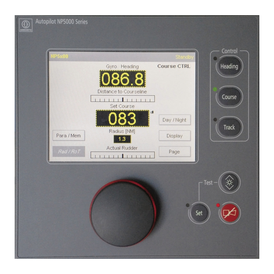
Page 18: Figure 1: Nautopilot® 5000 Series, Operator Unit
NautoPilot® 5000 Series 102-890.NG001-NG003 Operator Manual Figure 1: NautoPilot® 5000 Series, Operator Unit NautoPilot® 5100 Manual adaption to weather and sea state with 6 sets of parameters (such as rudder, counter rudder, yawing). - Heading Control - Track Control (in combination with Raytheon ECDIS) NautoPilot®... - Page 19 NautoPilot® 5000 Series 102-890.NG001-NG003 Operator Manual NautoPilot® 5400 Automatic adaption to weather and sea state using a rudder variance control. Increased rudder performance by adjusting ECONOMY/PRECISION mode (ECONOMY = low rudder activity; PRECISION = higher steering accuracy). Track change in Track Control with radius cross track distance parameters (XTD).
-
Page 20: Figure 2: Additional Autopilot Control Unit (Aacu)
NautoPilot® 5000 Series 102-890.NG001-NG003 Operator Manual Additional Autopilot Control Unit (AACU) Figure 2: Additional Autopilot Control Unit (AACU) The Additional Autopilot Control unit can be purchased in addition (optional) to the NautoPilot®. It is a slave console of the NautoPilot® and consists of a joystick and a 12 monitor. In addition, the AAC enables the graphical representation of a curved heading line in the Raytheon SYNAPSIS NX ECDIS and RADAR. -
Page 21: Figure 3: Standalone Application For The Nautopilot® 5000 Series
NautoPilot® 5000 Series 102-890.NG001-NG003 Operator Manual Standalone application (always with a connected Autopilot Interface, type102- 891) This application may only perform rudder control with an additional Raytheon Anschütz Autopilot Interface, type 102- 891. Figure 3: Standalone application for the NautoPilot® 5000 Series ECDIS Navigation data Status Analogue... -
Page 22: About The Manuals
NautoPilot® 5000 Series 102-890.NG001-NG003 Operator Manual An installation of 2 master NautoPilot® Operator Units is possible only in an integrated application not in combination with an Autopilot Interface. About the manuals There are 2 different manuals for the NautoPilot® 5000 Series: - Operator Manual - Service Manual The Operator Manual contains a basic description, technical data and... -
Page 23: Technical Data
NautoPilot® 5000 Series 102-890.NG001-NG003 Operator Manual Technical Data 1.2.1 Mechanical Data For dimensions, type of enclosure and weight see the appended Dimensional Drawing 102- 890.HP005 for Autopilot 102- 890.NG001, Dimensional Drawing 102- 890.HP015 for Autopilot 102- 890.NG002, NG003. 1.2.2 Electrical Data Supply voltage (plug B12) 24 V DC (18 to 36 V DC) Power consumption... - Page 24 NautoPilot® 5000 Series 102-890.NG001-NG003 Operator Manual Electrical Data Additional Autopilot Control Unit (AACU) 12” Monitor: Supply voltage 18- 34 V DC Galvanic isolated Optional Dual input DC power, Galvanic isolate Power consumption Approx. 25 W - 15 C to +55 C Ambient temperature (operation) - 25 C to +70 C Ambient temperature (storage)
-
Page 25: Explanation Of Parameters And Operation Modes
NautoPilot® 5000 Series 102-890.NG001-NG003 Operator Manual Explanation of parameters and operation modes 1.3.1 Yawing Must be set according to sea state. The yawing setting determines rudder activity and heading accuracy for the Autopilot‘s control properties. The possible range of parameter yawing is 1 to 6 (in increments of 1). -
Page 26: Counter Rudder
NautoPilot® 5000 Series 102-890.NG001-NG003 Operator Manual • pre- configured rate of turn not reached during heading change maneuver Decrease rudder if the intensity of the rudder movement is too strong. Increase the rudder intensity if the rudder movement is too weak during heading keeping. -
Page 27: Off Heading
NautoPilot® 5000 Series 102-890.NG001-NG003 Operator Manual magnetic compass. The monitoring threshold is set via the Page function (Page →Limit →Heading Monitor) at the initial display. It allows settings from 5 to 30 in increments of 1. The difference between Gyro heading and magnetic heading exceeds the preset threshold, an alert is generated. -
Page 28: Course Trim
NautoPilot® 5000 Series 102-890.NG001-NG003 Operator Manual Note: The desired value for the rate of turn (RoT) depends on the physical characteristics of the ship. The ship should be able to perform the turning value. Desired rates of turn exceeding the turn capability of the ship result in the OFF heading alarm being triggered before the ships heading reaches the desired Set Heading. -
Page 29: Track Econ
NautoPilot® 5000 Series 102-890.NG001-NG003 Operator Manual 1.3.8 Track Econ This parameter is for NP5500 only and is used to adjust the Economy Mode (see section 1.3.10) in Track Control. If the value of this parameter is increased, rudder activity will be reduced. 1.3.9 Acceleration Monitor (for NautoPilot®... -
Page 30: Basic Operation Modes
NautoPilot® 5000 Series 102-890.NG001-NG003 Operator Manual The different designations are caused by different steering philosophies, different manufacturers and different user requests. It is absolute necessary to become familiar with its designation and function within a steering system. For the steering system described in this manual, the switch has the switch positions HAND and AUTO but with different functions depending on the application. -
Page 31: Explanation Of Used Symbols
NautoPilot® 5000 Series 102-890.NG001-NG003 Operator Manual 1.4.1 Explanation of used symbols Some symbols are used to explain these modes. Below mentioned table shows their meaning. Table 2 Used symbols Symbol Meaning Key actuation LED flashing LED out LED alight Acoustical signal on Acoustical signal off Top bar of the display. -
Page 32: Operation Mode Heading Control
NautoPilot® 5000 Series 102-890.NG001-NG003 Operator Manual Standalone application: If the status Standby is displayed in Autopilot Display and the Main Steering Switch is switched into a switch position with Autopilot control, the NautoPilot® is active at once in Heading control. Attention: The NautoPilot®... - Page 33 NautoPilot® 5000 Series 102-890.NG001-NG003 Operator Manual The set heading value is adjusted via the rotary knob and activated either by the SET button or by pressing down the rotary knob. A direct heading change can be performed by pressing down and turning the rotary knob;...
-
Page 34: Figure 6: Heading Control After Manual Set Heading Adjustment
NautoPilot® 5000 Series 102-890.NG001-NG003 Operator Manual Figure 6: Heading Control after manual set heading adjustment * Standalone application: By switching the Main Steering Switch to AUTO the Autopilot controls at once in Heading mode. AS application: Autopilot must display Manual before. Then, by switching the Main Steering Switch to AUTO, Standby is displayed and the NautoSteer System is ready for control (but the Autopilot is not active). -
Page 35: Operation Mode Course Control (- Not For Np 5100 - )
NautoPilot® 5000 Series 102-890.NG001-NG003 Operator Manual 1.4.4 Operation mode Course Control (- not for NP 5100 - ) Figure 6: Principle of Course Control versus Heading Control Figure 7: Principle of Course Control versus Heading Control Actual heading: 85 Course to steer: 85 Drift Heading Control Actual heading: 93... -
Page 36: Figure 8: Explanations For A Heading Change In Course Control
NautoPilot® 5000 Series 102-890.NG001-NG003 Operator Manual Figure 8: Explanations for a heading change in Course Control A direct set Course Over Ground change can be performed by pressing and turning the rotary knob. In this mode the ship follows the new value after release of the rotary knob. -
Page 37: Figure 10: Course Control After Manual Set Heading Adjustment
NautoPilot® 5000 Series 102-890.NG001-NG003 Operator Manual threshold for the distance to course line in Course Control. Figure 10: Course Control after manual set heading adjustment * Independent the type of application (Standalone or AS) a switch over to Course Control is possible only if the control mode is Heading before (see section 1.4.3). -
Page 38: Operation Mode Track Control
NautoPilot® 5000 Series 102-890.NG001-NG003 Operator Manual Change maneuver is finished (+/- 1 to the Set Course over Ground) the drift correction becomes active again and the caution is deleted. Rate of Turn influence on Course Control The Rate of Turn upon activation of Course Control must not exceed 30/minute. Speed influence on Course Control The speed before activation of Course Control mode must not be less than this value, which is configured as the Low speed value. -
Page 39: Figure 11: Principle Of Track Control
NautoPilot® 5000 Series 102-890.NG001-NG003 Operator Manual Values for RAD and RoT from the ECDIS are displayed at the Autopilot during Track Control. They may be different from the values which have been adjusted at the Autopilot beforehand and they may exceed the adjustable range of the Autopilot. The speed value of ECDIS must not be different from the speed value for the control function of the Autopilot. - Page 40 NautoPilot® 5000 Series 102-890.NG001-NG003 Operator Manual FROM- WPT FROM- WPT is the previous waypoint. NEXT- WPT NEXT- WPT is the waypoint following TO- WPT. Wheel- over- line. The line of the track where the planned track change maneuver is intended to start. Approach- Time The approach time is the time before the WOL when the approach message is indicated on the NautoPilot®...
- Page 41 NautoPilot® 5000 Series 102-890.NG001-NG003 Operator Manual 1. The Autopilot is in the operating mode of Heading Control. 2. Track Control is activated from RAYTHEON Anschütz ECDIS. In general: Controller parameter like rudder, yawing, economy etc. can be adjusted at the Autopilot.
-
Page 42: Starting Track Control By Raytheon Anschütz Ecdis
NautoPilot® 5000 Series 102-890.NG001-NG003 Operator Manual 1.4.5.1 Starting Track Control by RAYTHEON Anschütz ECDIS To activate Track Control mode from the RAYTHEON Anschütz ECDIS the NautoPilot® has to be in Heading Control mode and a planned track has to be available at the EC- DIS. -
Page 43: Figure 12: Example For Go- To- Waypoint Maneuver For Np5100, Np5300 And Np5400
NautoPilot® 5000 Series 102-890.NG001-NG003 Operator Manual As soon as the operating mode is manually changed over from Track Control to Heading Control, RoT, 15 /min appears. The rudder limit is set to 10 again. The following sections 1.4.5.1.1 and 1.4.5.1.2 describe 2 types of maneuvers for going to the planned track after starting Track Control. -
Page 44: Figure 13: Geometrical Requirements Of Go- To- Waypoint Maneuvers
NautoPilot® 5000 Series 102-890.NG001-NG003 Operator Manual Requirements for Track Control using the NP5500 Figure 13: Example of Five Different GO- TO- WAYPOINT maneuvers depending on initial heading Figure 14: Geometrical Requirements of GO- TO- WAYPOINT maneuvers Track TO- WPT 10 NM 10000001052 Edition: 003... - Page 45 NautoPilot® 5000 Series 102-890.NG001-NG003 Operator Manual A) The initial position must be before the track and less than 10 nautical miles away. 11 Track 56 191 TO- WPT 281 2000 101 4000 281 101 Meters 6000 4000 2000 B) The initial heading must be between track course minus 45 and track course plus 135...
-
Page 46: Changing Over To Track Control, Go- To- Waypoint Maneuver
NautoPilot® 5000 Series 102-890.NG001-NG003 Operator Manual 1.4.5.1.1 Changing over to Track Control, GO- TO- WAYPOINT Maneuver (See also Figure 12 and Figure 13) Start Track Control at the ECDIS as GO- TO- WAYPOINT maneuver. Note: The following alert will be displayed on the ECDIS only for NP5100, NP5300 and NP5400 (also refer to ECDIS manual). -
Page 47: Changing Over To Track Control Return- To- Track Maneuver
NautoPilot® 5000 Series 102-890.NG001-NG003 Operator Manual 1.4.5.1.2 Changing over to Track Control RETURN- TO- TRACK Maneuver Dependent on the use of the ECDIS, it is also possible to define a RETURN- TO- TRACK maneuver on the ECDIS and to transmit it to the Autopilot. Approaching a track is then performed like resuming Track Control after an interruption. -
Page 48: Figure 15: Changing Over To Track Control - On Transmitting A From- Wpt By The Ecdis
NautoPilot® 5000 Series 102-890.NG001-NG003 Operator Manual Figure 15: Changing over to Track Control - on transmitting a FROM- WPT by the ECDIS NOTE : In case of failure of the ECDIS during Track Control, automatic change- over from Track Control to Heading Control takes place. -
Page 49: Track Change Maneuver
NautoPilot® 5000 Series 102-890.NG001-NG003 Operator Manual 1.4.5.1.3 Track Change Maneuver (see Figure 16) Attention! The track change maneuvers are planned and checked on the ECDIS. No check within the Autopilot takes place. A limitation, however, is incorporated. If a non- realizable small radius is transmitted to the Autopilot, this may lead to hard- over rudder positions! On planning the routes, attention is to be paid to the fact that from the end of the radius of a track change maneuver to the beginning of the radius of the next track... - Page 50 NautoPilot® 5000 Series 102-890.NG001-NG003 Operator Manual Procedure of the Track Change Maneuver Indications Comment/Notes An alert is displayed at the top bar of the display (see section 7). WOP IN x MIN OR LESS x minutes before the WOP. Track The approach time is transmitted from the ECDIS to the Autopilot.
-
Page 51: Figure 17: Extreme Case Example Of A Track Change Maneuver
NautoPilot® 5000 Series 102-890.NG001-NG003 Operator Manual Special alerts for the NP5500 Note: If the WPTs are very close together and if a long APPROACH time has been adjusted, it may happen that the APPROACH alarm of the following WPT appears already during the current track change maneuver: Indications Comment/Notes... -
Page 52: Interruption Of Track Control
NautoPilot® 5000 Series 102-890.NG001-NG003 Operator Manual 1.4.5.1.4 Interruption of Track Control Interruption of Track Control is possible as follows: - Change- over of the operating mode of Track Control to Heading Control on the operator unit of the Autopilot. - Change- over of the operating mode of Track Control to manual control by switching over the operating mode on the steering mode selector. - Page 53 NautoPilot® 5000 Series 102-890.NG001-NG003 Operator Manual Special alerts for the NP5500 This procedure is indicated by messages at the top bar of the display: Track change maneuver starting. An alert is displayed at the to bar of the display (see section 7). Changed Waypoints Should be acknowledged.
-
Page 54: End Of Track
NautoPilot® 5000 Series 102-890.NG001-NG003 Operator Manual 1.4.5.1.6 End of Track Via marking the last track point at the ECDIS, the track controller (Autopilot) recognizes the end of a track. Indications Comment/Notes An alert is displayed at the top bar of the display (see section 6). x minutes left to the last track point. -
Page 55: Error Considerations
NautoPilot® 5000 Series 102-890.NG001-NG003 Operator Manual 1.4.5.1.7 Error Considerations No Position - No or invalid Status - No Heading (see section 7.3.2.1) - Missing Waypoint - Track control impossible. ATTENTION: If an error occurs during Track Control, the operating mode changes from Track Control to Heading Control. -
Page 56: 1.4.5.1.7.1 No Position
NautoPilot® 5000 Series 102-890.NG001-NG003 Operator Manual 1.4.5.1.7.1 No Position The Autopilot monitors the position interface. In the normal case, the position is trans- mitted to the Autopilot once per second. Should the position fail to come in for longer than approx. 5 seconds, the following alert appears at the top bar of the display (see section 7): Indications Comment/Notes... - Page 57 NautoPilot® 5000 Series 102-890.NG001-NG003 Operator Manual the following alert appears on the display: Indications Comment/Notes An alert is displayed at the top bar of the display (see section 7). Both messages swapping. Track Control Interrupted 2 acoustical pulses. No ECDIS Status The operating mode changes from Track Control to Heading Control.
-
Page 58: Missing Waypoint (Np5500 Only)
NautoPilot® 5000 Series 102-890.NG001-NG003 Operator Manual 1.4.5.1.7.3 Missing Waypoint (NP5500 only) Should disturbances occur on the interface between ECDIS and Autopilot, and the Auto- pilot does not receive WPTs, this will be indicated on the operator unit at the end of the track change maneuver. The following alert appears on the display: Indications Comment/Notes An alert is displayed at the top bar of the display (see section 7). -
Page 59: Figure 19: Intended Return- To- Track Maneuver Impossible With The Ship Too Close To The To- Wpt
NautoPilot® 5000 Series 102-890.NG001-NG003 Operator Manual Figure 19: Intended RETURN- TO- TRACK maneuver impossible, Ship too Close to the TO- WPT - If (when Track Control is activated) the distance of the current ship’s position to the track is greater than the distance between FROM- WPT and TO- WPT or greater than 10 nautical miles. - Page 60 NautoPilot® 5000 Series 102-890.NG001-NG003 Operator Manual difference of the track courses is >135 Indications Comment/Notes An alert is displayed at the top bar of the display (see section 7). Both messages swapping. Track Control Interrupted 2 acoustical pulses. The operating mode changes from Distance TO/NEXT- Waypoint too short Track Control to Heading Control.
-
Page 61: Operation Mode Waypoint Steering
NautoPilot® 5000 Series 102-890.NG001-NG003 Operator Manual 1.4.6 Operation mode Waypoint Steering Important Note: Please refer to chapter 4.5.2 before using waypoint steering mode! Waypoint steering is possible with NP 5100 or NP5300 only! In waypoint steering mode the route - consisting of 2 or more waypoints - is planned on a GPS, chart plotter or equivalent navigation system. -
Page 62: Override
NautoPilot® 5000 Series 102-890.NG001-NG003 Operator Manual 1.4.8 Override In general: This mode is indicated (at the NautoPilot® Operator Unit) when a manual steering element (steering control unit) with an override function interrupts a control mode of the Autopilot. This steering element can be a handwheel, a FU Tiller or an NFU Tiller. To interrupt an Autopilot control mode a steering element must be configured for this function before. -
Page 63: Operation
NautoPilot® 5000 Series 102-890.NG001-NG003 Operator Manual 2 Operation Operation elements at the NautoPilot® Operator Unit Figure 21: NautoPilot® Operator Unit (operation elements) Table 3 NautoPilot® Operator Unit (operation elements) Pos. Designation Remarks Figure 20/1 Touchscreen For the display of data and operation of the Autopilot via soft- keys. - Page 64 NautoPilot® 5000 Series 102-890.NG001-NG003 Operator Manual Figure 20/2 HEADING button Activates Heading Control mode. with 2 LEDs LED (upper, green) indicates the selected steering mode. LED (lower, yellow) indicates: - Selected steering mode, but NautoPilot® Operation Unit is inactive (control from a second NautoPilot®...
- Page 65 NautoPilot® 5000 Series 102-890.NG001-NG003 Operator Manual Figure 20/5 DIM button Adjusts brightness of illumination and display. See also section 6.3 for dimming active/inactive NautoPilot® Operator Units. Figure 20/6 Acknowledges alarm or status messages. ACK button with LED (red blinking) indicates the first LED (red) occurrence of an alarm or status message (blinking) or that an acknowledged alarm or...
-
Page 66: Structure Of Parameter And Adjustments
NautoPilot® 5000 Series 102-890.NG001-NG003 Operator Manual Structure of parameter and adjustments Figure 22: Structure to adjust parameters and values Initial display (main display) Yawing Economy/Precision Parameter/Memory Rudder Counter rudder Radius/Rate of Turn Day/Night Heading/Rudder Plot Yawing Display Rudder Track Data Counter Rudder Ship Load Track... -
Page 67: Touchscreen Functions / Adjustments
NautoPilot® 5000 Series 102-890.NG001-NG003 Operator Manual Touchscreen functions / adjustments After switching on the NautoPilot® Operator Unit, the display below appears. Figure 23: First display (after switching ON the NautoPilot® Operator Unit) Fields with grey lined rectangles are softkeys. By touching these softkeys other/additional functions are called up/displayed. -
Page 68: Table 4 Operating And Monitoring Elements Of Initial Display After Turning-On
NautoPilot® 5000 Series 102-890.NG001-NG003 Operator Manual Table 4 Operating and monitoring elements of initial display after turning-on Function Figure 22/1 Indicates the type of NautoPilot®: NP 5100, NP 5300, NP 5400 or NP 5500. Figure 22/2 Alert and status bar (top bar of the display). Alerts and status information are displayed alphanumerical. - Page 69 NautoPilot® 5000 Series 102-890.NG001-NG003 Operator Manual Figure 22/9 Resolution icon. Softkey to switch the resolution of the set heading value between 1 and 1/10. Figure 22/10 Softkey for switching between night and day modes. Figure 22/11 Softkey for selecting displays with other content: HDG/Rudder plot: displays heading versus rudder position in a recorded graphic mode.
-
Page 70: Tendency Bar
NautoPilot® 5000 Series 102-890.NG001-NG003 Operator Manual 2.3.1 Tendency Bar This bar shows the tendency of data displayed above the bar. There are 3 different forms to display the information: Figure 24: Tendency bar 10000001052 Edition: 003... -
Page 71: Switching Between Night And Day Displays
NautoPilot® 5000 Series 102-890.NG001-NG003 Operator Manual 2.3.2 Switching between night and day displays Figure 25: First display (after switching ON the NautoPilot® Operator Unit in night mode, black/white) Use this softkey (see Figure 24) to switch between preset day or night displays (see configuration, Service Manual). -
Page 72: Switching And Adjusting Rad/Rot
NautoPilot® 5000 Series 102-890.NG001-NG003 Operator Manual 2.3.3 Switching and Adjusting Rad/RoT Figure 26: First Display (heading changes with RoT is selected). Heading changes can be performed with a Rate of Turn (RoT) limit or with a limited radius. The respective mode can be selected with the Rad/RoT softkey. The currently selected mode is displayed (Figure 25, Pos. -
Page 73: Using And Switching Between Economy And Precision Mode (Not For Np 5100)
NautoPilot® 5000 Series 102-890.NG001-NG003 Operator Manual 2.3.4 Using and switching between Economy and Precision mode (not for NP 5100) Figure 27: Initial Display (Eco/Prec switchover) In Economy mode a low rudder activity is selected, in Precision a higher rudder activity is selected. The selected mode is displayed in the top bar. -
Page 74: Displays For Additional Information And Records
NautoPilot® 5000 Series 102-890.NG001-NG003 Operator Manual 2.3.5 Displays for additional information and records Figure 28: Switching to display selection see section 2.3.6 Softkeys displayed are dependent on configuration and/or type of NautoPilot Table 5 Softkeys for Display Selection Function Figure 27/1 Softkey Cancel for switching back to the initial display. -
Page 75: Hdg/Rudder Plot Display
NautoPilot® 5000 Series 102-890.NG001-NG003 Operator Manual 2.3.5.1 HDG/Rudder Plot display Figure 29: Displays for HDG /Rudder Plot Figure 30: Example of a SET request after a parameter has been changed 10000001052 Edition: 003... -
Page 76: Table 6 Softkeys For Hdg/Rudder Plot Display
NautoPilot® 5000 Series 102-890.NG001-NG003 Operator Manual This display in Figure 28 shows numerical and graphical recorded information on: - Actual heading - Set heading or Set COG or Track Course (depends on selected control mode) - Rudder position angle - Current operating mode at the Autopilot which is still active. Table 6 Softkeys for HDG/Rudder Plot Display Function... - Page 77 NautoPilot® 5000 Series 102-890.NG001-NG003 Operator Manual Function Figure 28/17 Softkeys for changing selected rudder parameters. Changes must be acknowledged with SET (a small icon is displayed after a change has been made, see Figure 29). Figure 28/18 Softkey for switching back to the previous display, without a transfer of changed values.
-
Page 78: Track Data Display
NautoPilot® 5000 Series 102-890.NG001-NG003 Operator Manual 2.3.5.2 Track Data display This display shows numerical and graphical recorded information on: - Actual heading - Set COG or Track Course - Distance to course line or Cross Track Error (depends on selected control mode) - Current operating mode at the Autopilot which is still active. -
Page 79: Figure 32: Example Of A Request To Press Set After A Parameter Has Been Changed
NautoPilot® 5000 Series 102-890.NG001-NG003 Operator Manual Furthermore, a graphic record shows the track, its configured max. distance, the course- line, the ship itself and the course to steer for the course line. Parameter settings will change the same parameters which can be set with the Page function (see section 2.3.6). - Page 80 NautoPilot® 5000 Series 102-890.NG001-NG003 Operator Manual Figure 30/11 For Adaptive mode only and not for NP 5100. Softkey for changing/entering the ship load condition parameter (see also section 1.3.4). Value range: 10% to 100% (in increments of 10%). Use the + and - softkeys to make a change. Changes must be acknowledged with SET (a small icon is displayed after a change has been made, see Figure 31).
-
Page 81: Np 5000 Actual Rudder Display
NautoPilot® 5000 Series 102-890.NG001-NG003 Operator Manual 2.3.5.3 NP 5000 Actual Rudder display Please note: The NP 5000 Actual Rudder” display indicates the actual rudder angle used for the steering gear control system and may be used as back- up only for the Rudder Angle Indicator required by SOLAS V 19 as amended. -
Page 82: Table 8 Softkeys For Np 5000 Actual Rudder Display
NautoPilot® 5000 Series 102-890.NG001-NG003 Operator Manual Table 8 Softkeys for NP 5000 Actual Rudder Display Function Figure 32/1 Display with graphic information on the actual rudder angle Figure 32/2 Information on heading source and actual heading value. Figure 32/3 Set heading value. For Course Control this display is designated as Presel.COG (Preselected Course Over Ground) after turning the rotary knob, Set COG after releasing the knob (in increments of 1... -
Page 83: Acceleration Monitor Display (- Only For Np 5400 And Np 5500 - )
NautoPilot® 5000 Series 102-890.NG001-NG003 Operator Manual 2.3.5.4 Acceleration Monitor display (- only for NP 5400 and NP 5500 - ) In the Acceleration Monitor display the current operating mode for the Autopilot is also displayed in the upper right corner below the status bar. In Figure 33 the current mode is standby. -
Page 84: Table 9 Softkeys For Acceleration Monitor Display
NautoPilot® 5000 Series 102-890.NG001-NG003 Operator Manual Table 9 Softkeys for Acceleration Monitor Display Function Figure 33/1 Indication of max. speed (as calculated by the settings of acceleration limit, see next display Setup Accel.Limit). Figure 33/2 Indication of max. RoT (as limited by the settings of acceleration limit, see next display Setup Accel.Limit). -
Page 85: Figure 35: Example Of A Request To Press "Set" After A Parameter Has Been Changed
NautoPilot® 5000 Series 102-890.NG001-NG003 Operator Manual Function Figure 33/17 Softkey for switching an alarm ON or OFF if the acceleration overshoots an adjusted acceleration limit value (percentage value). Possible settings are: - Off (no alert) - On (an alert is activated if the limit is reached or exceeded). -
Page 86: Application Hints For The Acceleration Monitor
NautoPilot® 5000 Series 102-890.NG001-NG003 Operator Manual 2.3.5.4.1 Application hints for the Acceleration Monitor The Acceleration Monitor supports the user adjusting RAD/RoT limits in a way for that the acceleration limit will not be met. Additionally, if the calculated limits (speed, RAD/ RoT) are about to reach the acceleration limit, an alert is generated to inform the user. - Page 87 NautoPilot® 5000 Series 102-890.NG001-NG003 Operator Manual The calculated cross acceleration limit is displayed on the fly (see position 20). Additionally (during the input of the respective value) an alert is indicated in the Acceleration Monitor page if this value could lead to an alert (by a small attention sign behind the respective line).
-
Page 88: Position Monitoring Display (- Not For Np 5100 - )
NautoPilot® 5000 Series 102-890.NG001-NG003 Operator Manual 2.3.5.5 Position Monitoring display (- not for NP 5100 - ) Please note (only for Course Control): It is advisable to check the ”Set”, ”Drift” and ”Off Position Limit” settings to prevent needless alarms, which are caused by changing environmental conditions (drift). -
Page 89: Figure 37: Display For The Position Monitoring Function (Limit Exceeded)
NautoPilot® 5000 Series 102-890.NG001-NG003 Operator Manual Displayed position sensors can be GPS, Loran C, ECDIS or Dead Reckoning, the corresponding data source is displayed with GPS,LC, II or Dead Recko (Figure 35 shows a dead reckoned position). In the upper right corner below the status bar the current operating mode of the Autopilot is displayed. -
Page 90: Figure 38: Display For The Position Monitoring Function (Limit Exceeded And Different Drift)
NautoPilot® 5000 Series 102-890.NG001-NG003 Operator Manual Figure 38: Display for the Position Monitoring function (limit exceeded and different drift) DEAD RECK As shown in Figure 37 there is a comparison between GPS0 and a dead reckoned position: - The limit of 530 m has been exceeded before (dotted line: drift line). - An alert was activated and acknowledged. -
Page 91: Figure 39: Display For The Position Monitoring Function (General Information)
NautoPilot® 5000 Series 102-890.NG001-NG003 Operator Manual Figure 39: Display for the Position Monitoring function (general information) Table 10 Definitions within the Position Monitoring Display Function Range rings. Figure 38/1 These range rings are displayed proportional to the Off Position Limit. The steps displayed are: 1 m- 10 m- 100 m- 1000 m 2 m- 20 m- 200 m- 2000 m... -
Page 92: Figure 40: Displays For Position Monitoring (Adjustments)
NautoPilot® 5000 Series 102-890.NG001-NG003 Operator Manual Figure 40: Displays for Position Monitoring (adjustments) 10000001052 Edition: 003... -
Page 93: Table 11 Softkeys For Position Monitoring Displays
NautoPilot® 5000 Series 102-890.NG001-NG003 Operator Manual Table 11 Softkeys for Position Monitoring Displays Function Figure 39/1 Display, shows the position of a maximum of 2 GPS receivers and their relative position to the ship. The position sensor in use (control function of the Autopilot) is always in the center. -
Page 94: Figure 41: Example Of A Request To Press Set After A Parameter Has Been Changed
NautoPilot® 5000 Series 102-890.NG001-NG003 Operator Manual Function Figure 39/14 Softkey for adjusting the observed heading. This value can be input from the user and influences the position of Dead Reckoning on the display. Value range: 000.0 to 359.9 (in increments of 0.1). Figure 39/15 Softkey for adjusting the Off Position Limit. -
Page 95: Ship Data Display
NautoPilot® 5000 Series 102-890.NG001-NG003 Operator Manual 2.3.5.6 Ship Data display Figure 42: Display of Ships data (example) All the above- mentioned ship’s data can be edited in the configuration mode (see Ser- vice Manual) except for the Software Version, GUI Version (Graphic User Interface) and License ID. -
Page 96: Page Function
NautoPilot® 5000 Series 102-890.NG001-NG003 Operator Manual 2.3.6 Page function Use this function to change current parameters, values, data sources and limits. Depending on which operation the Page softkey is currently performing, one of the following displays will be shown: - Display with no indication - Display with softkey to perform changes - Display with the main current settings Figure 43: Page function displays... -
Page 97: Figure 44: Indicated Values/Parameters
NautoPilot® 5000 Series 102-890.NG001-NG003 Operator Manual Figure 44: Indicated values/parameters (Page function) Table 12 Indicated values/parameters (Page function) Function Figure 43/1 Adjusted Counter rudder parameter (see also section 1.3.3). Value range: 1 to 9 (in increments of 1). Figure 43/2 Adjusted rudder parameter (see also section 1.3.2). -
Page 98: Heading
NautoPilot® 5000 Series 102-890.NG001-NG003 Operator Manual Figure 45: Calling- up values for adjustment (Page function) Use the Value softkey to open another window and select heading, speed or RoT &Radius adjustments. 2.3.6.1 Heading Figure 46: Heading source selection (Page function) After pressing the Heading softkey the display will appear as shown in Figure 45. - Page 99 NautoPilot® 5000 Series 102-890.NG001-NG003 Operator Manual Notes on the heading source selection: Gyro/GPS If only one Gyro Compass is connected, this compass acts as the active heading source. If several Gyro Compasses are connected within a navigation system, the compass with the better performance or with an ascertained sequence is selected for the task.
-
Page 100: Figure 47: Heading Source Selection ("Page" Function) - Heading Source Not Available Or Ins
NautoPilot® 5000 Series 102-890.NG001-NG003 Operator Manual INS (or heading sensor is not available) If the Autopilot is installed in an Integrated Navigation System (INS) the heading information is distributed to the Autopilot via a Consistent Common Reference System (CCRS). Therefore, the heading source cannot be selected (see Figure 46). In this case the respective radio button is neither visible nor operable. -
Page 101: Figure 49: Speed Sensor And Heading Sensor Doubtful
NautoPilot® 5000 Series 102-890.NG001-NG003 Operator Manual Figure 49: Speed sensor and Heading sensor doubtful For doubtful values of speed and heading sensor, the background turns into yellow color (Figure 49). Figure 50: Speed sensor and Heading sensor failed In case of failure of both speed and heading sensor, both areas turn into yellowish orange color and the display shows dashes instead of values. -
Page 102: Speed
NautoPilot® 5000 Series 102-890.NG001-NG003 Operator Manual 2.3.6.2 Speed Figure 51: Speed source and speed value (Page function) Speed sensor not available. System In normal operation the system shows the Speed Through Water (STW) In data failure of STW the system shows (if a second speed sensor is connected) the Speed Over Ground (SOG). -
Page 103: Rot & Radius
NautoPilot® 5000 Series 102-890.NG001-NG003 Operator Manual 2.3.6.3 RoT & Radius Figure 52: RoT & Radius (Page function) Use the + and - softkeys to adjust the max. turn rate for a heading/course change. Press the SET button to transmit this value to the controller. Value range: 5/min to 500/min (in increments of 1/min). -
Page 104: Toe Angle
NautoPilot® 5000 Series 102-890.NG001-NG003 Operator Manual 2.3.6.4 Toe Angle The steering characteristics and energy efficiency on some vessels with 2 rudders or pod- drives can be optimized if the individual rudders are controlled with an offset (toe angle) to each other. A toe angle sets the rudder inwards or outwards with a constant value. The optimum toe angle depends on the speed. -
Page 105: Limit Values
NautoPilot® 5000 Series 102-890.NG001-NG003 Operator Manual 2.3.6.5 Limit values Figure 54: Limit values (Page function) Table 13 Meanings of Limit Values (Page function) Function Figure 53/1 This adjustment is used during the control function of the Autopilot and should be adjusted within the configured limits. It sets limits for command rudder output of the Autopilot. -
Page 106: Parameter Settings
NautoPilot® 5000 Series 102-890.NG001-NG003 Operator Manual Function Figure 53/5 Track Limit Autopilot; this value activates an alert if the adjusted value exceeds a track limit (stb or pt) - active in Course Control mode only. Value range: 10 m to 2000 m, (in increments of 1 m). Figure 53/6 OFF Position Limit;... -
Page 107: Figure 56: Example Of A Request To Press Set After A Parameter Has Been Changed
NautoPilot® 5000 Series 102-890.NG001-NG003 Operator Manual Table 14 Meanings of parameter Settings (Page function) Function Figure 54/1 Softkey for changing/entering the yawing parameter (see also section 1.3.1). Value range: 1 to 6 (in increments of 1). Use the + and - softkeys to make a change. Changes must be acknowledged with SET (a small icon is displayed after a change has been made, see Figure 55). -
Page 108: Test Of Nautopilot® Operator Unit
NautoPilot® 5000 Series 102-890.NG001-NG003 Operator Manual 2.3.7 Test of NautoPilot® Operator Unit Note: This test is not used to test the Autopilot control functions. This test serves for testing the function of the display, the LEDs, the rotary knob and the buttons. -
Page 109: Quick Tune
NautoPilot® 5000 Series 102-890.NG001-NG003 Operator Manual 2.3.8 Quick Tune It is possible to store up to 5 parameter sets with preset parameters for yawing, rudder and counter rudder. The application of parameter sets is only possible when the selected mode is non- adaptive (see Figure 56). -
Page 110: Calling Up Parameter Sets
NautoPilot® 5000 Series 102-890.NG001-NG003 Operator Manual 2.3.8.1 Calling up parameter sets Figure 57: Displays for parameter sets Figure 58: Displays for parameter sets 10000001052 Edition: 003... -
Page 111: Table 15 Meanings Of Parameter Memory
NautoPilot® 5000 Series 102-890.NG001-NG003 Operator Manual Table 15 Meanings of Parameter Memory Function Figure 57/1 Actual values of the parameters yawing, rudder and counter rudder. These values must not be identical to one of the below parameters sets. A selected parameter set (parameter set M1 is selected as shown) can be changed with the Parameter softkey at the initial display - this changed parameter values are displayed as Actual. -
Page 112: Modification Of A Parameter Set
NautoPilot® 5000 Series 102-890.NG001-NG003 Operator Manual 2.3.8.2 Modification of a parameter set Figure 59: Modification of a parameter set Please note: A modified parameter value will not be automatically transmitted to the controller; it is stored only. After the modification, the modified parameter set must be transmitted to the controller by pressing the SET button. -
Page 113: Switching On/Off
NautoPilot® 5000 Series 102-890.NG001-NG003 Operator Manual Table 16 Meanings of parameters for Parameter sets Function Figure 58/1 Softkey for changing/entering the counter rudder parameter (see also section 1.3.3). Value range: 0 to 9 (in increments of 1). Use the + and - softkeys to make a change. Changes must be acknowledged with SET. - Page 114 NautoPilot® 5000 Series 102-890.NG001-NG003 Operator Manual Intentionally left blank 10000001052 Edition: 003...
-
Page 115: Summary Of Possible Adjustments, Parameter Settings And Configurations
NautoPilot® 5000 Series 102-890.NG001-NG003 Operator Manual 3 Summary of possible adjustments, parameter settings and configurations The table below is a summary of all adjustable settings arranged in alphabetical order, together with a reference to the section in the Operator Manual in which the setting is explained. - Page 116 NautoPilot® 5000 Series 102-890.NG001-NG003 Operator Manual Set [deg] Direction of the drift for dead reckoning in 2.3.5.5 Position Monitoring. 1.3.4, Ship Load Typical ship behavior depending on the load 2.3.5.1, 2.3.5.2, 2.3.6.5 Speed Speed for acceleration limit 2.3.5.4 Track Limit Autopilot Autopilot alarm activation if the adjusted track 2.3.6.4 limit is exceeded.
-
Page 117: Modes Of Operation, Recommended Adjustments/Settings, Examples
NautoPilot® 5000 Series 102-890.NG001-NG003 Operator Manual 4 Modes of operation, recommended adjustments/settings, examples Explanation of symbols used at the Autopilot Key activation LED flashing LED off LED on Audible signal on Audible signal off Rotary knob pressed/released Rotary knob turned and pressed Rotary knob turned 10000001052 Edition: 003... -
Page 118: General Notes And Recommendations
NautoPilot® 5000 Series 102-890.NG001-NG003 Operator Manual General notes and recommendations - Before using the Autopilot, the NautoPilot® Operator Unit and the Autopilot Interface (if installed) must be configured. Adjustment, configuration and operation are strongly influenced by the steering system and its application/performance. Therefore, it is absolutely obligatory that configuration, adjustments and operation must be performed by well- trained, experienced personnel only. -
Page 119: Heading Control
NautoPilot® 5000 Series 102-890.NG001-NG003 Operator Manual - A set course change (heading change or preselected heading change) is not possible if: An operating mode is selected which does not allow a heading change via the Autopilot. A display is selected which does not display the heading change value, for example during adjustments. -
Page 120: Table 18 Checks To Be Made Before Switching From Standby To Heading Control
NautoPilot® 5000 Series 102-890.NG001-NG003 Operator Manual Table 18 Checks to be made before switching from Standby to Heading Control Check Comment Heading source The desired heading source is shown above the actual heading value. The heading source can be adjusted via the Page function: Softkeys Page→Value→Heading (see also section 2.3.6.1 and Figure 44) Heading value... -
Page 121: Procedure To Switch From Standby Or Override To Heading Control Mode
NautoPilot® 5000 Series 102-890.NG001-NG003 Operator Manual 4.3.2 Procedure to switch from Standby or Override to Heading Control mode Please note: - Switching over to an automatic mode should be performed after carrying out the checks according to section 4.3.1. - After switching over, the actual heading will be taken as the set heading. Table 19 Procedure to switch from Standby to Heading Control Mode 10000001052... -
Page 122: Procedure To Switch From Course Control Mode To Heading Control Mode
NautoPilot® 5000 Series 102-890.NG001-NG003 Operator Manual Please note: - If there is no automatic switchover to Heading Control (in the event of a wrong or corrupted configuration) it is strongly advised that the operator presses the Heading Control button. - It is necessary to observe the Autopilot control function after activation. - For heading changes in Heading Control mode, see section 4.3.6. -
Page 123: Procedure To Switch From Track Control Mode To Heading Control Mode
NautoPilot® 5000 Series 102-890.NG001-NG003 Operator Manual 4.3.4 Procedure to switch from Track Control mode to Heading Control mode Table 21 Procedure to switch from Track Control mode to Heading Control Mode Track Control mode is active. The mode is displayed at the top right corner of the display (Track Ctrl.). -
Page 124: Switching Off The Heading Control Mode
NautoPilot® 5000 Series 102-890.NG001-NG003 Operator Manual 4.3.5 Switching off the Heading Control mode Leaving Heading Control mode is possible only by switching to other control modes or to change the steering mode (manual): - For switching over to Course Control, see section 4.4. - For switching over to Track Control, see section 4.5. -
Page 125: Heading Change In Heading Control Mode
NautoPilot® 5000 Series 102-890.NG001-NG003 Operator Manual 4.3.6 Heading change in Heading Control mode There are 3 ways to order a heading change (set heading): Table 23 Procedure for changing heading in Heading Control mode - Changing preselected heading value with rotary knob and SET button. - Changing preselected heading value with turned rotary knob and pressed rotary knob (SET function of the rotary knob). -
Page 126: Preselected Heading Change In Heading Control Mode
NautoPilot® 5000 Series 102-890.NG001-NG003 Operator Manual Preselected heading Acknowledging the value with the SET button or only with the rotary knob has the same result, but the procedure is different. This procedure can be used, if a heading change is in preparation. Direct heading Change the heading directly if a heading change is based on a bearing. - Page 127 NautoPilot® 5000 Series 102-890.NG001-NG003 Operator Manual Heading Control mode is active. The mode is displayed at the top right corner of the display (Heading Ctrl.). Turning the rotary knob will change the preselected heading value. Please note: After approx. 15 seconds of inactivity from rotary knob, the primary heading value is displayed again.
-
Page 128: Direct Heading Change In Heading Control Mode
NautoPilot® 5000 Series 102-890.NG001-NG003 Operator Manual 4.3.6.2 Direct heading change in Heading Control mode Table 25 Procedure for a direct heading change in Heading Control mode Mode Heading Control is active. The mode is displayed at the top right corner of the display (Heading Ctrl.). -
Page 129: Course Control
NautoPilot® 5000 Series 102-890.NG001-NG003 Operator Manual Course Control - A direct switchover from ”Manual” mode to ”Course Control” mode is not possible. - A direct switchover from ”Track Control” mode to ”Course Control” mode is not possible. - A direct switchover to ”Course Control” is only possible from ”Heading Control”... - Page 130 NautoPilot® 5000 Series 102-890.NG001-NG003 Operator Manual Check Comment Speed source The desired speed source is shown and can be adjusted via the Page function: Softkeys Page→Value→Speed (see also section 2.3.6.2 and Figure 50) Speed value The speed value must be valid. If speed value is invalid, select Manual Speed.
-
Page 131: Procedure To Switch From Heading Control Mode To Course Control Mode
NautoPilot® 5000 Series 102-890.NG001-NG003 Operator Manual 4.4.2 Procedure to switch from Heading Control mode to Course Control mode A mode change from ”Heading Control” to ”Course Control” should not be performed during a heading change in ”Heading Control”, because of the limited turn rate and the fact that the actual heading is set to ”set course”... -
Page 132: Procedure To Switch From Track Control Mode To Course Control Mode
NautoPilot® 5000 Series 102-890.NG001-NG003 Operator Manual 4.4.3 Procedure to switch from Track Control mode to Course Control mode It is not possible to switch directly from Track Control mode to Course Control mode . It is only possible to switch from Heading Control mode to Course Control mode. 4.4.4 Switching off Course Control mode It is not possible to switch off Course Control mode - only switching over to other... -
Page 133: As Application
NautoPilot® 5000 Series 102-890.NG001-NG003 Operator Manual 4.4.5 AS application Table 29 Procedure to switch off Course Control mode in AS application HAND AUTO Switching the Main Steering Switch into position HAND, switches the Autopilot to Manual No LED for activated control modes will light up. The mode change is displayed at the top right corner of the display (Course Ctrl. -
Page 134: Course Change In Course Control Mode
NautoPilot® 5000 Series 102-890.NG001-NG003 Operator Manual 4.4.6 Course change in Course Control mode After a course change is indicated in Course Control a new course change can be ordered until the Course Approach” alert is not indicated. Please note: each time the heading is changed in this way, the ”Distance to Course line”... -
Page 135: Table 30 Procedure For A Course Change In Course Control Mode
NautoPilot® 5000 Series 102-890.NG001-NG003 Operator Manual Table 30 Procedure for a course change in Course Control mode Course Control mode is active. The mode is displayed at the top right corner of the dis- play (Course Ctrl.). Turning the rotary knob will change the set Course Over Ground value. - Page 136 NautoPilot® 5000 Series 102-890.NG001-NG003 Operator Manual Turning the rotary knob will change the set Course Over Ground value. Please note: After approx. 15 seconds of inactivity from the rotary knob, the previous Course Over Ground value Preselected COG is displayed again. 125.8 This value is displayed in italic and inverted colors.
-
Page 137: Lost Position Value In Course Control Mode
NautoPilot® 5000 Series 102-890.NG001-NG003 Operator Manual 4.4.7 Lost position value in Course Control mode The Course Control mode is executed for at least 2 minutes and the top bar (yellowish orange) displays Dead Reckoning no Position during this time. If no valid position is available after 2 minutes, the Course Control mode is stopped and a switchover to Heading Control mode is performed (an appropriate message will be displayed at the top bar). -
Page 138: Preconditions For Switching To Track Control Mode
NautoPilot® 5000 Series 102-890.NG001-NG003 Operator Manual 4.5.2 Preconditions for switching to Track Control mode Table 31 Checks to be made before switching to Track Control with RAYTHEON Anschütz ECDIS Check Comment Heading source The desired heading source is shown above the actual heading value. -
Page 139: Waypoint Steering Mode In Combination With Gps, Chart Plotter Or Equivalent Navigation System
NautoPilot® 5000 Series 102-890.NG001-NG003 Operator Manual Check Comment Course Trim Adjust Course Trim threshold for deviation from Set Track Course Over Ground. Softkeys Limit → Limit Page (see also section 1.3.7 and 2.3.6.4) Heading monitor Adjust Heading Monitor threshold according to traffic in sea area;... - Page 140 NautoPilot® 5000 Series 102-890.NG001-NG003 Operator Manual and thus these systems are not tested by authorities / classification societies. Please note: The waypoint steering mode may only be used on non- SOLAS vessels. It must not be used on vessels following SOLAS regulation. Regulation 3 of SOLAS, Chapter I, Part 1 describes the following exceptions for non- SOLAS vessels: (a) The present regulations, unless expressly provided otherwise, do not apply to:...
- Page 141 NautoPilot® 5000 Series 102-890.NG001-NG003 Operator Manual - The NautoPilot® version is NP 5100 or NP 5300 (for NautoPilot® with a higher performance e.g. for type NP 5400 and NP 5500 it is not possible to connect to GPS, chart plotter or equivalent navigation system).
-
Page 142: Table 32 Checks To Be Made Before Switching To Waypoint Steering Using Gps, Chart Plotter Or Equivalent Navigation Systems
NautoPilot® 5000 Series 102-890.NG001-NG003 Operator Manual Table 32 Checks to be made before switching to waypoint steering using GPS, chart plotter or equivalent navigation systems Check Comment Heading source The desired heading source is shown above the actual heading value. The source is supposed to be the same as displayed at the ECDIS. -
Page 143: Switching Off Track Control And Waypoint Steering Mode
NautoPilot® 5000 Series 102-890.NG001-NG003 Operator Manual Track Limit Adjust Track Limit threshold according to traffic in sea area; the more traffic, the smaller the threshold. Adjusted Track Limit must be the same as adjusted at the ECDIS. Softkeys Limit → Limit Page (see also section 2.3.5.2 and 2.3.6.4) OFF Position Limit Adjust Limit threshold for deviation between first and second position sensor, e.g. - Page 144 NautoPilot® 5000 Series 102-890.NG001-NG003 Operator Manual 10000001052 Edition: 003...
- Page 145 NautoPilot® 5000 Series 102-890.NG001-NG003 Operator Manual Faults detected at the ECDIS during Track Control mode will stop this mode. An automatic switchover to Heading Control mode is performed. On straight leg: The RAD and RoT values and the rudder limit, which were adjusted by the operator, are now used and displayed.
-
Page 146: Description Additional Autopilot Control Unit (Aacu)
NautoPilot® 5000 Series 102-890.NG001-NG003 Operator Manual 5 Description Additional Autopilot Control Unit (AACU) With the Additional Autopilot Control Unit, it is possible to control the NautoPilot® in the modes: - Heading Control - and Course Control. In addition, a Curved Heading Line is displayed in the Raytheon SYNAPSIS NX ECDIS and RADAR systems. -
Page 147: Operation Elements Of The Additional Autopilot Control Unit
NautoPilot® 5000 Series 102-890.NG001-NG003 Operator Manual Operation elements of the Additional Autopilot Control Unit Table 34 Operation elements AACU No. Section Description Date and Time The section Date and Time Information displays the Date, UTC and local time. Information 2 Navigation The section NAVIGATION displays the related navigational sensor information. -
Page 148: Navigation
NautoPilot® 5000 Series 102-890.NG001-NG003 Operator Manual 5.2.2 Navigation This Section displays Navigation Information. Below the designations are the sensors that supply the data. On the right side, a colored quality indicator may appear if the sensor has doubtful integrity or no valid and plausible data. Example: Table 35 Example Section Navigation (AACU) -
Page 149: Autopilot Values
NautoPilot® 5000 Series 102-890.NG001-NG003 Operator Manual 5.2.3 Autopilot Values Figure 60: Autopilot Values Table 37 Description of the Quality Indicators according to IEC 62288 No. Area / Element Description SET HEADING / Displays the set heading or course that was set via SET COURSE the NautoPilot®... -
Page 150: Panel
NautoPilot® 5000 Series 102-890.NG001-NG003 Operator Manual For more information see SYNAPSIS NX manual. 5.2.5 Panel Figure 61: Section Panel Table 39 Section Panel Designation Function Softkey ACTIVE Activates the panel. The NautoPilot® is under control off the Additional Autopilot Control Unit. Indicator lamp Green = The NautoPilot®... - Page 151 NautoPilot® 5000 Series 102-890.NG001-NG003 Operator Manual Softkey COURSE CON- Activates the steering mode course control. TROL 10000001052 Edition: 003...
-
Page 152: Control
NautoPilot® 5000 Series 102-890.NG001-NG003 Operator Manual 5.2.6 Control Figure 62: Section Control Table 40 Section Control No Area / Element Description Softkey Activates the Curved Heading Line (CHL). The CHL is displayed in the Raytheon SYNAPSIS NX ECDIS Curved Heading and RADAR systems. -
Page 153: Table 41 Joystick Operation
NautoPilot® 5000 Series 102-890.NG001-NG003 Operator Manual the value changes until the joystick is brought back to its initial position. Table 41 Joystick operation Direction One movement Held in Forwards The turning radius increases Changes of the values until re- (Rad +) 0.1 NM leased. -
Page 154: Operation
NautoPilot® 5000 Series 102-890.NG001-NG003 Operator Manual Operation With the Additional Autopilot Control Unit, it is possible to control the NautoPilot® in the modes: - Heading Control - and Course Control. NOTE: No Track Control able. The Track Control mode is started by a track planning system (ECDIS, Raytheon Anschütz). - Page 155 NautoPilot® 5000 Series 102-890.NG001-NG003 Operator Manual Procedure: 1. Select the softkey ACTIVE in the section PANEL. 2. The softkey is highlighted and the indicator lamp lights green. 3. Select the softkey COURSE CONTROL in the Section PANEL. 4. The softkey is highlighted and the STEERING MODE displays Course Crl. Step result: 5.
-
Page 156: Set Rudder Limit
NautoPilot® 5000 Series 102-890.NG001-NG003 Operator Manual Set Rudder Limit Select the entry field RUDDER LIMIT in the Section CONTROL. The softkey SET switches to active. Enter the required value via the on- screen numerical pad or via the softkeys ▼ and ▲ . Confirm the entries with the check mark and then with the softkey SET. -
Page 157: Alerts Of The Additional Autopilot Control Unit
NautoPilot® 5000 Series 102-890.NG001-NG003 Operator Manual Alerts of the Additional Autopilot Control Unit Alerts are given acoustically and are shown on the NautoPilot® Operator Unit, ECDIS and Radar. For more Information see chapter 7 Alert/status message handling for NautoPilot® and the chapters Alert Area and Alert Management in the Software Manuals of ECDIS and Radar. -
Page 158: Switching Between Night And Day Display (Dimming) Change Display Colors
NautoPilot® 5000 Series 102-890.NG001-NG003 Operator Manual Switching between night and day display (dimming) Change Display Colors The display can be configured for different conditions by changing the color combinations. Following color modes are available: - Bright Sun Colors Bright on white background - Day Colors - White Dark on white background - Day Colors - Black... -
Page 159: Adjust Dimming
NautoPilot® 5000 Series 102-890.NG001-NG003 Operator Manual Adjust Dimming • Select Menu from the top right corner of the display. -- The Menu submenu opens. • Select Dimming. The Dimming menu opens. • Select Central or Local with the switch- button. •... -
Page 160: Superior Operation Features
NautoPilot® 5000 Series 102-890.NG001-NG003 Operator Manual 6 Superior operation features Changing the license key This function is identical to a NautoPilot® Operator Unit upgrade. A check/reconfiguration should be performed after changing a license key. See the Service Manual for the NautoPilot® Operator Unit Software update A software update should be performed only by experienced and well- trained personnel. -
Page 161: Handling Of More Than One Nautopilot® Operator Unit In A Steering System (Master - Slave - Application)
NautoPilot® 5000 Series 102-890.NG001-NG003 Operator Manual Handling of more than one NautoPilot® Operator Unit in a steering system (Master - Slave - application) It is possible to install more than one NautoPilot® Operator Unit in a steering system. However, only one of the NautoPilot® Operator Units is a master, whilst the others are designated as slaves. -
Page 162: Figure 65: Principle Of Master Slave Nautopilot® Operator Unit
NautoPilot® 5000 Series 102-890.NG001-NG003 Operator Manual Exceptions or additional information to applications with several NautoPilot® Operator Units are given in the corresponding sections. Please note: Central Dimming cannot be executed by slave NautoPilot® Operator Units. Dimming changes can only be executed locally at each slave NautoPilot®... -
Page 163: Ou Display Indication
NautoPilot® 5000 Series 102-890.NG001-NG003 Operator Manual for Track Control mode. General information: At the active NautoPilot® Operator Unit a green LED is on at the corresponding mode button. At the inactive NautoPilot® Operator Units a yellow LED is on at the corresponding mode button. -
Page 164: Procedure To Change Nautopilot® Operator Unit Status (Active - Inactive)
NautoPilot® 5000 Series 102-890.NG001-NG003 Operator Manual 6.3.2 Procedure to change NautoPilot® Operator Unit status (active - inactive) This procedure is independent of master or slave NautoPilot® Operator Unit. Table 42 Procedure to change NautoPilot® Operator Unit status (active - inactive) without change of control mode Please note: - It is necessary to observe the Autopilot control function after this procedure. -
Page 165: Table 43 Procedure To Change Nautopilot® Operator Unit Status (Active - Inactive) With Change Of Control Mode
NautoPilot® 5000 Series 102-890.NG001-NG003 Operator Manual Table 43 Procedure to change NautoPilot® Operator Unit status (active - inactive) with change of control mode Please note: - It is necessary to observe the Autopilot control function after this procedure. If an active slave fails (no power), the system will automatically switch over to the master NautoPilot®... -
Page 166: Handling Of More Than One Nautopilot® Operator Unit In A Steering System (Master - Master - Application)
NautoPilot® 5000 Series 102-890.NG001-NG003 Operator Manual Handling of more than one NautoPilot® Operator Unit in a steering system (Master - Master - application) It is possible to install more than one Master NautoPilot® Operator Unit in a steering system (if there are 2 or more complete independent steering positions - for example). - Page 167 NautoPilot® 5000 Series 102-890.NG001-NG003 Operator Manual Intentionally left blank 10000001052 Edition: 003...
-
Page 168: Alert/Status Message Handling
NautoPilot® 5000 Series 102-890.NG001-NG003 Operator Manual 7 Alert/status message handling Please note: It is advisable to acknowledge each warning, caution and information message. It is strongly advisable to acknowledge each alarm and to resolve its cause before continuing with a control mode. -
Page 169: Table 44 Alarms/Messages Alerts
NautoPilot® 5000 Series 102-890.NG001-NG003 Operator Manual Alarms and warnings are displayed alphanumerical in the red or yellowish orange top bar of the display (see Figure 63). The icon of the alert flashes until the ACK button is pressed (acknowledgement). Please note: In order to avoid unintended acknowledgement of a new incoming alert, the push button ACK is deactivated for 1 second after receiving a new alert. - Page 170 NautoPilot® 5000 Series 102-890.NG001-NG003 Operator Manual (see also Table of alert icons, section 7.1) In addition to the acoustic signal, the (red) ACK LED flashes. The acoustic signal has both a low volume signal and a loud signal (from 2 different signal horns).
-
Page 171: Alert Management Icons
NautoPilot® 5000 Series 102-890.NG001-NG003 Operator Manual Alert Management Icons Below mentioned table shows the alert / warning or caution icons which are displayed at the top bar of the display. These icons are based on the IEC 62923- 1:2018. Please note: It is only possible to display messages with an APIF add-on if there is an autopilot interface connected (standalone application) and the NautoPilot®... -
Page 172: Possible Alarms, Warnings And Cautions
NautoPilot® 5000 Series 102-890.NG001-NG003 Operator Manual Possible alarms, warnings and cautions Please note: Messages/alarms with the ”APIF” add- on are only possible if an Autopilot Interface is installed (standalone application) and the NautoPilot® Operator Unit is configured for an application with an Autopilot Interface. For a detailed description of alarms, warnings and cautions, see alert list in the annex. -
Page 173: Other Alarms
NautoPilot® 5000 Series 102-890.NG001-NG003 Operator Manual Other alarms The next sections show alarm and warnings which are either transmitted to a central alarm panel as Central Alarm combined as part of a System Alarm. 7.3.1 Central alarm (For some classification societies only). The NautoPilot®... -
Page 174: Specials On Heading Failure
NautoPilot® 5000 Series 102-890.NG001-NG003 Operator Manual Alarms can be: - Power Failure - No Heading - Simulated sensor data - Missing n APIFs - Too many APIFs on the CAN bus, please check configuration - The Autopilot has performed an automatic Reset The first action to take when one of the above alarms has been activated should be to reset the NautoPilot®... -
Page 175: Annex
NautoPilot Operator Unit 8 Annex 8 Annex 8.1 Alerts 8.1.1 Alert List Note Messages / alarms with the APIF add-on are only possible if an autopilot interface is installed (standalone application) and the NautoPilot Operator Unit is configured as an ® application with an autopilot interface. - Page 176 NautoPilot Operator Unit 8 Annex Alert Title Catego- Escala- Possible Cause Remedy tion Alert Description Priority APIF RESTART Warning APIF was restarted Check APIF Manual. by internal watchdog. APIF SOFTWARE RESTART: CHECK APIF RUD. STOPPED Warning No CAN-connection Check APIF Manual, Warning between APIF and use manual steering.
- Page 177 NautoPilot Operator Unit 8 Annex Alert Title Catego- Escala- Possible Cause Remedy tion Alert Description Priority GYRO FAILED Caution none Gyro connected at Check Gyro connect- APIF failed. ed to APIF. APIF GYRO HEAD- ING FAILED: CHECK HDG SENSOR GYRO FAILED Caution Gyro connected at Check Gyro connect-...
- Page 178 NautoPilot Operator Unit 8 Annex Alert Title Catego- Escala- Possible Cause Remedy tion Alert Description Priority HCS STOPPED Alarm Power supply of the Use manual steering. operator unit is out- Check supply volt- POWER FAILURE: side of tolerable lim- age. Reset operator CHECK POWER its.
- Page 179 NautoPilot Operator Unit 8 Annex Alert Title Catego- Escala- Possible Cause Remedy tion Alert Description Priority MAG FAILED Warning Backup magnetic Check magnetic Warning heading sensor failed. heading sensor. BACK UP HDG SENSOR FAILED: CHECK SENSOR MAG HDG SEL. Warning Magnetic heading Warning sensor selected for MAGNETIC HEAD-...
- Page 180 NautoPilot Operator Unit 8 Annex Alert Title Catego- Escala- Possible Cause Remedy tion Alert Description Priority CHECK LIMITS Warning Track control was in- The operator shall Warning terrupted. check the limits for CHECK RUD- RAD/ROT and Rud- DER/ROT/RAD der limits. Those LIMITS might have changed by the TCS.
- Page 181 NautoPilot Operator Unit 8 Annex Alert Title Catego- Escala- Possible Cause Remedy tion Alert Description Priority HDG MON DIS. Caution none HEADING MONI- TOR DISABLED HDG UNCORR. Caution none Gyro reports uncor- Check Gyro rected heading infor- CHECK HEADING mation. CORRECTION INP NOT ACCEPT- Caution none...
- Page 182 NautoPilot Operator Unit 8 Annex Alert Title Catego- Escala- Possible Cause Remedy tion Alert Description Priority POS CHANGED Caution Warning POSITION SENSOR CHANGED POS INVALID Caution none Selected Position Select valid position sensor sends no or sensor, check posi- SWITCH TO VALID invalid data.
- Page 183 NautoPilot Operator Unit 8 Annex Alert Title Catego- Escala- Possible Cause Remedy tion Alert Description Priority NEW CRS 3MIN Warning Next leg change Acknowledge warn- Alarm is due in 3 min- ing, Check maneuver. COURSE CHANGE utes. Track control IN 3 MIN to BN- IEC62065:2014 (30 s)*...
- Page 184 NautoPilot Operator Unit 8 Annex Alert Title Catego- Escala- Possible Cause Remedy tion Alert Description Priority TCS STOPPED Warning Track control inter- Check route. Alarm rupted. Distance be- DISTANCE TO WPT tween From and To TOO SHORT to BN- waypoint too closeor selected Waypoint to (30 s)* start track control is...
- Page 185 NautoPilot Operator Unit 8 Annex Alert Title Catego- Escala- Possible Cause Remedy tion Alert Description Priority TCS STOPPED Warning Leg change maneu- Check connection Alarm ver was not initiated. and configuration of CHECK ROUTE Track control was in- ECDIS, use heading to BN- terrupted.
- Page 186 NautoPilot Operator Unit 8 Annex Alert Title Catego- Escala- Possible Cause Remedy tion Alert Description Priority TCS STOPPED Warning Track control inter- Select gyro heading Alarm rupted, magnetic source. MAG HDG SELECT- heading source se- ED: SELECT GYRO to BN- lected. HEADING (30 s)* TRCK-...
- Page 187 NautoPilot Operator Unit 8 Annex Alert Title Catego- Escala- Possible Cause Remedy tion Alert Description Priority NEW TRACK Caution none Track change maneu- none necessary. ver is complete. NEW TRACK 000° NO RADIUS Caution none NO APPROACH RAD. DEFINED NO TRACK CRS Caution none CHECK CONNEC-...
- Page 188 NautoPilot Operator Unit 8 Annex Alert Title Catego- Escala- Possible Cause Remedy tion Alert Description Priority WP CHANGED Caution none The current TO-Way- point was changed WAYPOINTS HAVE while in track control CHANGED XTE EXCEEDED Alarm Ship is outside of ad- Check surroundings, justed limits around use manual steering...
- Page 189 NautoPilot Operator Unit 8 Annex Alert Title Catego- Escala- Possible Cause Remedy tion Alert Description Priority CC STOPPED Warning Position jump detect- Alarm ed, Course control is POSITION JUMP: interrupted. Fallback CHECK POSITION to BN- is Heading control. HDG MONITOR Warning Doubtful heading in- Check heading infor- formation or heading...
- Page 190 NautoPilot Operator Unit 8 Annex Alert Title Catego- Escala- Possible Cause Remedy tion Alert Description Priority CHECK DR Caution none Position monitor for Check settings for po- Course control uses sition monitor CHECK DEAD DR. Default settings RECKONING DRIFT used for drift and set. SETTINGS CRS APPROACH Caution...
- Page 191 NautoPilot Operator Unit 8 Annex Alert Title Catego- Escala- Possible Cause Remedy tion Alert Description Priority NEW CRS 3MIN Warning Track 62065:2002, early track change COURSE CHANGE warning. IN 3 MIN (30 s)* TCS UNAVAIL. Warning Track 62065:2002, Track route. Alarm impossible track TRACK CONTROL warning.
Need help?
Do you have a question about the NautoPilot 5000 Series and is the answer not in the manual?
Questions and answers