Sign In
Upload
Manuals
Brands
Raytheon Anschütz Manuals
Marine Equipment
NP 5100
Raytheon Anschütz NP 5100 Manuals
Manuals and User Guides for Raytheon Anschütz NP 5100. We have
1
Raytheon Anschütz NP 5100 manual available for free PDF download: Operator's Manual
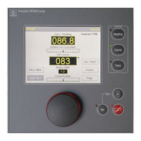
Raytheon Anschütz NP 5100 Operator's Manual (191 pages)
Brand:
Raytheon Anschütz
| Category:
Marine Equipment
| Size: 4.52 MB
Table of Contents
Table of Contents
5
1 Description
17
Figure 1: Nautopilot® 5000 Series, Operator Unit
18
Figure 2: Additional Autopilot Control Unit (AACU)
20
Table 1 Overview Nautopilot® Types (Variants)
20
Figure 3: Standalone Application for the Nautopilot® 5000 Series
21
Figure 4: Integrated Application of Nautopilot® 5000 Series
21
About the Manuals
22
Technical Data
23
Electrical Data
23
Mechanical Data
23
Explanation of Parameters and Operation Modes
25
Rudder
25
Yawing
25
Counter Rudder
26
Heading Monitor
26
Ship Load (for Adaptive Mode Only)
26
OFF Heading
27
Course Trim
28
Figure 5: Course Trim Angle
28
Acceleration Monitor (for Nautopilot® 5400 and 5500 Only)
29
Adaptive Mode (Weather Adaptivity)
29
Information about the Steering Switch
29
Track Econ
29
Basic Operation Modes
30
Explanation of Used Symbols
31
Standby and Not Ready
31
Table 2 Used Symbols
31
Operation Mode Heading Control
32
Figure 6: Heading Control after Manual Set Heading Adjustment
34
Figure 7: Principle of Course Control Versus Heading Control
35
Operation Mode Course Control (- Not for NP 5100 - )
35
Figure 8: Explanations for a Heading Change in Course Control
36
Figure 9: Principle of Course Control Display
36
Figure 10: Course Control after Manual Set Heading Adjustment
37
Operation Mode Track Control
38
Figure 11: Principle of Track Control
39
Starting Track Control by RAYTHEON Anschütz ECDIS
42
Figure 12: Example for GO- TO- WAYPOINT Maneuver for NP5100, NP5300 and NP5400
43
Figure 13: Geometrical Requirements of GO- TO- WAYPOINT Maneuvers
44
Figure 14: Example of Five Different GO- TO- WAYPOINT Maneuvers Depending on the Initial Heading
44
Changing over to Track Control, GO- TO- WAYPOINT Maneuver
46
Changing over to Track Control RETURN- TO- TRACK Maneuver
47
Figure 15: Changing over to Track Control - on Transmitting a FROM- WPT by the ECDIS
48
Figure 16: Procedure of the Track Change Maneuver (Example)
49
Track Change Maneuver
49
Figure 17: Extreme Case Example of a Track Change Maneuver
51
Changing TO- WPT and NEXT- WPT Without Interrupting Track Control
52
Figure 18: Changing TO- WPT and NEXT- WPT Without Interrupting Track Control
52
Interruption of Track Control
52
End of Track
54
Error Considerations
55
1.4.5.1.7.1 no Position
56
1.4.5.1.7.2 no or Invalid Status from ECDIS
56
Missing Waypoint (NP5500 Only)
58
Track Control Impossible (NP5500 Only)
58
Figure 19: Intended RETURN- TO- TRACK Maneuver Impossible with the Ship too Close to the TO- WPT
59
Figure 20: Track Control Impossible with the Distance to the Track too Large
59
Manual
61
Operation Mode Waypoint Steering
61
Override
62
2 Operation
63
Operation Elements at the Nautopilot® Operator Unit
63
Figure 21: Nautopilot® Operator Unit (Operation Elements)
63
Table 3 Nautopilot® Operator Unit (Operation Elements)
63
Structure of Parameter and Adjustments
66
Figure 22: Structure to Adjust Parameters and Values
66
Touchscreen Functions / Adjustments
67
Figure 23: First Display (after Switching on the Nautopilot® Operator Unit)
67
Table 4 Operating and Monitoring Elements of Initial Display after Turning-On
68
Figure 24: Tendency Bar
70
Tendency Bar
70
Figure 25: First Display (after Switching on the Nautopilot® Operator Unit in Night Mode, Black/White)
71
Switching between Night and Day Displays
71
Figure 26: First Display (Heading Changes with Rot Is Selected)
72
Switching and Adjusting Rad/Rot
72
Figure 27: First Display (Eco/Prec Switchover)
73
Using and Switching between Economy and Precision Mode (Not for NP 5100)
73
Displays for Additional Information and Records
74
Figure 28: Switching to Display Selection
74
Table 5 Softkeys for Display Selection
74
Figure 29: Displays for HDG /Rudder Plot
75
Figure 30: Example of a SET Request after a Parameter Has Been Changed
75
Hdg/Rudder Plot Display
75
Table 6 Softkeys for Hdg/Rudder Plot Display
76
Figure 31: Displays for Track Data
78
Track Data Display
78
Figure 32: Example of a Request to Press SET after a Parameter Has Been Changed
79
Table 7 Softkeys for Track Data Display
79
Figure 33: Display for NP 5000 Actual Rudder with One and 2 Rudders
81
NP 5000 Actual Rudder Display
81
Table 8 Softkeys for NP 5000 Actual Rudder Display
82
Acceleration Monitor Display (- Only for NP 5400 and NP 5500 - )
83
Figure 34: Displays for Acceleration Monitor
83
Table 9 Softkeys for Acceleration Monitor Display
84
Figure 35: Example of a Request to Press "SET" after a Parameter Has Been Changed
85
Application Hints for the Acceleration Monitor
86
Figure 36: Display for the Position Monitoring Function (no Limit Exceeded)
88
Position Monitoring Display (- Not for NP 5100 - )
88
Figure 37: Display for the Position Monitoring Function (Limit Exceeded)
89
Figure 38: Display for the Position Monitoring Function (Limit Exceeded and Different Drift)
90
Figure 39: Display for the Position Monitoring Function (General Information)
91
Table 10 Definitions Within the Position Monitoring Display
91
Figure 40: Displays for Position Monitoring (Adjustments)
92
Table 11 Softkeys for Position Monitoring Displays
93
Figure 41: Example of a Request to Press SET after a Parameter Has Been Changed
94
Figure 42: Display of Ships Data (Example)
95
Ship Data Display
95
Figure 43: Page Function Displays
96
Page Function
96
Figure 44: Indicated Values/Parameters
97
Table 12 Indicated Values/Parameters
97
Figure 45: Calling- up Values for Adjustment
98
Figure 46: Heading Source Selection
98
Heading
98
Figure 47: Heading Source Selection ("Page" Function) - Heading Source Not Available or ins
100
Figure 48: Heading Sensor Failed
100
Figure 49: Speed Sensor and Heading Sensor Doubtful
101
Figure 50: Speed Sensor and Heading Sensor Failed
101
Figure 51: Speed Source and Speed Value
102
Speed
102
Figure 52: Rot & Radius
103
Rot & Radius
103
Figure 53: Toe Angle
104
Toe Angle
104
Figure 54: Limit Values
105
Limit Values
105
Table 13 Meanings of Limit Values
105
Figure 55: Parameter Setting
106
Parameter Settings
106
Figure 56: Example of a Request to Press SET after a Parameter Has Been Changed
107
Table 14 Meanings of Parameter Settings
107
Test of Nautopilot® Operator Unit
108
Quick Tune
109
Figure 57: Selection of Adaptive and Non-Adaptive Mode
109
Calling up Parameter Sets
110
Figure 58: Displays for Parameter Sets
110
Table 15 Meanings of Parameter Memory
111
Figure 59: Modification of a Parameter Set
112
Modification of a Parameter Set
112
Switching ON/OFF
113
Table 16 Meanings of Parameters for Parameter Sets
113
3 Summary of Possible Adjustments, Parameter Settings and Configurations
115
Table 17 Summary of Possible Adjustments, Parameter Settings and Configurations
115
4 Modes of Operation, Recommended Adjustments/Settings, Examples
117
Explanation of Symbols Used at the Autopilot
117
General Notes and Recommendations
118
Heading Control
119
Precondition for Switching from Standby Mode to Heading Control Mode
119
Table 18 Checks to be Made before Switching from Standby to Heading Control
120
Procedure to Switch from Standby or Override to Heading Control Mode
121
Table 19 Procedure to Switch from Standby to Heading Control Mode
121
Procedure to Switch from Course Control Mode to Heading Control Mode
122
Table 20 Procedure to Switch from Course Control Mode to Heading Control Mode
122
Procedure to Switch from Track Control Mode to Heading Control Mode
123
Table 21 Procedure to Switch from Track Control Mode to Heading Control Mode
123
Switching off the Heading Control Mode
124
Table 22 Procedure to Switch off Heading Control Mode
124
Heading Change in Heading Control Mode
125
Table 23 Procedure for Changing Heading in Heading Control Mode
125
Preselected Heading Change in Heading Control Mode
126
Table 24 Procedure for Changing Preselected Heading in Heading Control Mode
126
Direct Heading Change in Heading Control Mode
128
Table 25 Procedure for a Direct Heading Change in Heading Control Mode
128
Course Control
129
Preconditions for Switching to Course Control Mode
129
Table 26 Checks to be Made before Switching to Course Control Mode
129
Procedure to Switch from Heading Control Mode to Course Control Mode
131
Table 27 Procedure to Switch from Heading Control Mode to Course Control Mode
131
Procedure to Switch from Track Control Mode to Course Control Mode
132
Switching off Course Control Mode
132
Table 28 Procedure to Switch off Course Control Mode in Standalone Application
132
AS Application
133
Table 29 Procedure to Switch off Course Control Mode in as Application
133
Course Change in Course Control Mode
134
Table 30 Procedure for a Course Change in Course Control Mode
135
Lost Position Value in Course Control Mode
137
Track Control
137
Track Control Mode with RAYTHEON Anschütz ECDIS
137
Preconditions for Switching to Track Control Mode
138
Table 31 Checks to be Made before Switching to Track Control with RAYTHEON Anschütz ECDIS
138
Waypoint Steering Mode in Combination with GPS, Chart Plotter or Equivalent Navigation System
139
Table 32 Checks to be Made before Switching to Waypoint Steering Using GPS, Chart Plotter or Equivalent Navigation Systems
142
Switching off Track Control and Waypoint Steering Mode
143
Table 33 Procedure to Switch off Track Control Mode
143
5 Description Additional Autopilot Control Unit (AACU)
146
Switching on / off
146
Operation Elements of the Additional Autopilot Control Unit
147
Date and Time Information
147
Table 34 Operation Elements AACU
147
Navigation
148
Table 35 Example Section Navigation (AACU)
148
Table 36 Description of the Quality Indicators According to IEC 62288
148
Autopilot Values
149
Menu
149
Figure 60: Autopilot Values
149
Table 37 Description of the Quality Indicators According to IEC 62288
149
Table 38 Menu Bar Content
149
Panel
150
Figure 61: Section Panel
150
Table 39 Section Panel
150
Control
152
Using the Joystick
152
Figure 62: Section Control
152
Figure 63: Joystick
152
Table 40 Section Control
152
Table 41 Joystick Operation
153
Operation
154
Heading Control
154
Course Control
154
Set Rudder Limit
156
Alerts of the Additional Autopilot Control Unit
157
Show / Hide the Curved Heading Line
157
Switching between Night and Day Display (Dimming) Change Display Colors
158
Adjust Dimming
159
6 Superior Operation Features
160
Changing the License Key
160
Software Update
160
Handling of more than One Nautopilot® Operator Unit in a Steering System (Master - Slave - Application)
161
Figure 64: Master- and Slave Nautopilot® Operator Units
161
Figure 65: Principle of Master Slave Nautopilot® Operator Unit
162
Figure 66: Indication ou Display" in Slave Operator Unit
163
OU Display Indication
163
Procedure to Change Nautopilot® Operator Unit Status (Active - Inactive)
164
Table 42 Procedure to Change Nautopilot® Operator Unit Status (Active - Inactive) Without Change of Control Mode
164
Table 43 Procedure to Change Nautopilot® Operator Unit Status (Active - Inactive) with Change of Control Mode
165
Handling of more than One Nautopilot® Operator Unit in a Steering System (Master - Master - Application)
166
Specifics for a Master - Master - Application
166
7 Alert/Status Message Handling
168
Figure 67: Alert Messages at the Nautopilot® Operator Unit (Example for Long Text)
168
Figure 68: Alert Messages at the Nautopilot® Operator Unit (Example for Short Text)
168
Table 44 Alarms/Messages Alerts
169
Alert Management Icons
171
Table 45 Alert Management Icons
171
Possible Alarms, Warnings and Cautions
172
Other Alarms
173
Central Alarm
173
System Alarm
173
Specials on Heading Failure
174
8 Annex
175
Advertisement
Advertisement
Related Products
Raytheon Anschütz NP 5300
Raytheon Anschütz NP 5400
Raytheon Anschütz NP 5500
Raytheon Anschütz NG002
Raytheon Anschütz ECDIS NX Compact
Raytheon Anschütz NautoPilot 5000 Series
Raytheon Anschütz Synapsis Conning NX
Raytheon Anschütz SYNAPSIS ECDIS
Raytheon Anschütz Categories
Compass
Marine Equipment
Autopilot System
Control Unit
Power distribution unit
More Raytheon Anschütz Manuals
Login
Sign In
OR
Sign in with Facebook
Sign in with Google
Upload manual
Upload from disk
Upload from URL