Table of Contents
Advertisement
Quick Links
Advertisement
Table of Contents

Related Manuals for Cabletron Systems WPIM T1


Summary of Contents for Cabletron Systems WPIM T1
- Page 1 Title Page WPIM-T1/DDS User’s Guide WPIM T1/DDS 9032750...
-
Page 3: Fcc Notice
Only qualified personnel should perform installation procedures. Cabletron Systems reserves the right to make changes in specifications and other information contained in this document without prior notice. The reader should in all cases consult Cabletron Systems to determine whether any such changes have been made. -
Page 4: Industry Canada Notice
Notice INDUSTRY CANADA NOTICE This digital apparatus does not exceed the Class A limits for radio noise emissions from digital apparatus set out in the Radio Interference Regulations of the Canadian Department of Communications. Le présent appareil numérique n’émet pas de bruits radioélectriques dépassant les limites applicables aux appareils numériques de la class A prescrites dans le Règlement sur le brouillage radioélectrique édicté... - Page 5 IMPORTANT: Before utilizing this product, carefully read this License Agreement. This document is an agreement between you, the end user, and Cabletron Systems, Inc. (“Cabletron”) that sets forth your rights and obligations with respect to the Cabletron software program (the “Program”) contained in this package.
-
Page 6: United States Government Restricted Rights
Government is subject to restrictions as set forth in subparagraph (c) (1) (ii) of the Rights in Technical Data and Computer Software clause at 252.227-7013. Cabletron Systems, Inc., 35 Industrial Way, Rochester, New Hampshire 03867-0505. WPIM-T1/DDS User’s Guide... -
Page 7: Declaration Of Conformity
___________________________________ Title Rochester, NH, USA ___________________________________ Location WPIM-T1/DDS User’s Guide 89/336/EEC 73/23/EEC Cabletron Systems, Inc. 35 Industrial Way PO Box 5005 Rochester, NH 03867 Mr. J. Solari Cabletron Systems Limited Nexus House, Newbury Business Park London Road, Newbury Berkshire RG13 2PZ, England... - Page 8 Notice WPIM-T1/DDS User’s Guide...
-
Page 9: Table Of Contents
INTRODUCTION...ix Using This Manual...ix Structure of This Guide...ix Related Manuals...x Document Conventions ...xi Getting Help... xii CHAPTER 1 OVERVIEW Firmware Revision... 1-2 WPIM-T1/DDS Features... 1-2 WAN Protocols ... 1-3 MIB Support... 1-3 CHAPTER 2 SETUP AND INSTALLATION Installing the WPIM-T1/DDS... 2-1 2.1.1 Unpacking the WPIM-T1/DDS ... - Page 10 Contents Full T-1 Configuration Using PPP ...3-11 3.3.1 T1 Service Physical Configuration ...3-12 3.3.2 T1 Interface Configuration...3-13 Fractional T-1 Configuration Using PPP ...3-14 3.4.1 T1 Physical Configuration ...3-15 3.4.2 T1 Interface Configuration...3-17 Frame Relay Configuration ...3-17 3.5.1 Frame Relay Physical Configuration ...3-18 3.5.2 Frame Relay Interface Configuration ...3-20 CHAPTER 4...
-
Page 11: Introduction
Welcome to the Cabletron Systems WPIM-T1/DDS User’s Guide. This manual provides hardware information and explains the use of Local Management to control and manage the Cabletron Systems WPIM-T1/DDS. The WPIM-T1/DDS is installed in and provides connectivity and functionality to the CSX400 and the HSIM-W6. The WPIM-T1/DDS provides full or fractional T1, or a DDS interface to these platforms. -
Page 12: Related Manuals
The following manuals may help the user to set up and manage the WPIM-T1/DDS: Cabletron Systems HSIM-W6 Installation Guide Cabletron Systems HSIM-W84 Installation Guide Cabletron Systems QuickSET Configuration Guide for CSX200, CSX400, CSX400-DC, HSIM-W6, and HSIM-W84 Cabletron Systems CyberSWITCH CSX400 and CSX400-DC Installation Guide... -
Page 13: Document Conventions
DOCUMENT CONVENTIONS The following conventions are used throughout this document: Note symbol. Calls the reader’s attention to any item of NOTE information that may be of special importance. Tip symbol. Conveys helpful hints concerning procedures or actions. Caution symbol. Contains information essential to avoid damage to the equipment. -
Page 14: Getting Help
A description of any action(s) already taken to resolve the problem (e.g., changing mode switches, rebooting the unit, etc.) • The serial and revision numbers of all involved Cabletron Systems products in the network • A description of your network environment (layout, cable type, etc.) •... -
Page 15: Chapter 1 Overview
• Install the WPIM-T1/DDS in a Wide Area Network host platform. Refer to Chapter 2 appropriate host manual (i.e., the Cabletron Systems CyberSWITCH CSX400 and CSX400-DC Installation Guide for other installation and troubleshooting procedures. • Access Local Management. Refer to the appropriate host platform Local Management User’s Guide for instructions on setting up and... -
Page 16: Firmware Revision
Chapter 1: Overview FIRMWARE REVISION Depending on the firmware version used in the WPIM-T1/DDS, some features described in this document may not be supported. Refer to the Release Notes shipped with the WPIM-T1/DDS to determine which features are supported. This manual covers Firmware Revision level 02.01.XX. Later revisions may be reflected in an updated manual. -
Page 17: Wan Protocols
MIB SUPPORT Refer to the Release Notes included with the host platform for a list of all MIBs supported by the WPIM-T1/DDS. For information about how to extract and compile individual MIBs, contact Cabletron Systems (refer to Getting Help). WPIM-T1/DDS User’s Guide... - Page 18 Chapter 1: Overview WPIM-T1/DDS User’s Guide...
-
Page 19: Chapter 2 Setup And Installation
For additional support related to the WPIM-T1/DDS, refer to the host platform manual into which the WPIM-T1/DDS is being installed. Locate the guide by clicking on the Cabletron Systems QuickSET program group icon after installing the QuickSET CD on your computer, or see Manuals in the Introduction. -
Page 20: Pre-Installation
Chapter 2: Setup and Installation 2.1.2 Pre-Installation To prepare the host platform for the WPIM-T1/DDS, proceed as follows: Turn off and disconnect the host platform from the power source. Mark all network cables attached to the host platform for ease of re-installation. -
Page 21: Post-Installation
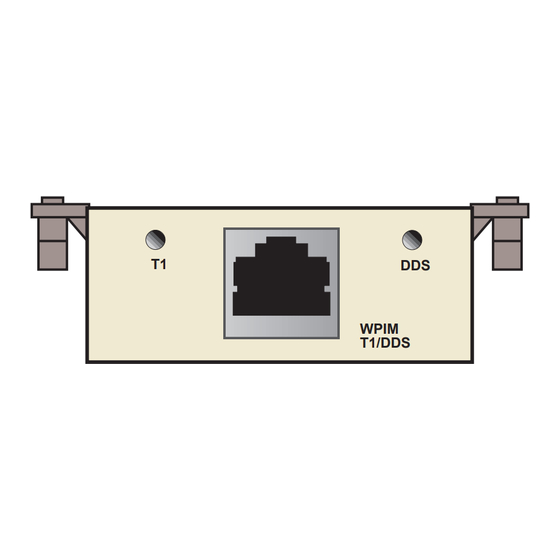
• After the host platform runs a self test, the CPU LED blinks green indicating normal operation. • If the CPU LED remains red, contact Cabletron Systems. WPIM-T1/DDS User’s Guide Installing the WPIM-T1/DDS WPIM Screws / D D... -
Page 22: Leds
Chapter 2: Setup and Installation LEDs The LEDs on the WPIM-T1/DDS indicate the service that the WPIM-T1/DDS is providing. (See WPIM-T1/DDS is operating in T1 mode. If the DDS LED is lit, the WPIM-T1/DDS is operating in DDS mode. The host platform displays LED indications of the WPIM-T1/DDS’s operation. -
Page 23: Wan Configuration
This is done using Network Tools, or MIB Navigator, depending on the host platform. Refer to the host platform user’s guide for information on how to navigate through the Local Management screens in order to access Network Tools. Follow these steps to configure the WPIM-T1/DDS for T1 or DDS service: Once in Network Tools, choose between T1 and DDS setup using this command:... -
Page 24: Connecting The Wan Cable To The Wpim-T1/Dds
Chapter 2: Setup and Installation CONNECTING THE WAN CABLE TO THE WPIM-T1/DDS Before connecting any cabling to the WPIM-T1/DDS, the WAN configuration must be complete. Refer to the previous section for information (Section 2.3.2) if the WAN configuration has not been completed. -
Page 25: Local Management For T1 Service
LOCAL MANAGEMENT FOR T1 SERVICE This chapter explains how to configure the WPIM-T1/DDS through Local Management for T1 service. The WAN Physical Configuration screen and the WAN Interface Configuration screen appear as Local Management menu selections when you install the WPIM-T1/DDS into a host module. Refer to the host platform User’s Guide for instructions about how to set up and access Local Management. -
Page 26: Chapter 3 Local Management For T1 Service
Chapter 3: Local Management for T1 Service THE WAN PHYSICAL CONFIGURATION SCREEN To access the WAN Physical Configuration screen, use the arrow keys to highlight the WAN SETUP menu item, then press ENTER. The screen shown in Figure 3-1 displays. When there is more than one WPIM installed into the host NOTE platform, information for the second WPIM will display next to... -
Page 27: Wan Physical Configuration Screen Fields
3.1.1 WAN Physical Configuration Screen Fields The following sections describe WAN Physical Configuration screen fields and provide instructions for setting them. The WAN Physical Configuration screen lets you configure the WPIM or “Physical Interface.” The Type field displays either T1 or DDS, depending on the NOTE mode selected using Network Tools. -
Page 28: Wpim Line Configuration Fields
Chapter 3: Local Management for T1 Service SAVE (Command) Saves the chosen configuration. WPIM X (Toggle) Enables the user to select the WPIM to be configured. Once it is selected, the user can enter the screens of the WPIM selected to modify the data. WAN INT CONFIG (Command) When this field is highlighted and the ENTER key is pressed, the WAN Interface Configuration screen displays. -
Page 29: The Wpim Timeslot Configuration Table
The WPIM Timeslot Configuration Table The WPIM Timeslot Configuration table allows the user to configure the way in which the Cabletron Systems WAN module uses the T1 line. The configuration table consists of 24 Timeslots. Each Timeslot must be assigned an Interface number (for example, 002 for an active Interface number or 000 if the Timeslot is not used). - Page 30 Chapter 3: Local Management for T1 Service Timeslots can be utilized in any way chosen. The WPIM-T1/DDS in T1 mode supports Time Division Multiplexing (TDM) allowing channelization of circuits (Timeslots) within the public network. For example, if the WPIM-T1/DDS has access to a full T1 (24 Timeslots), and the user wants to communicate with two other sites, the configuration might look like that shown in SITE #1...
-
Page 31: The Wan Interface Configuration Screen
Site #1 is using the full T1, so all the Timeslots must have an Interface assignment. Site #2 and Site #3 use only a fraction of the T1, but the total quantity of Timeslots must match those of Site #1. Unused Timeslots receive an Interface number of 000. -
Page 32: Wan Interface Configuration Screen Fields
The values 0-15 and 1008-1022 are reserved DLCI addresses. When using FR PtoMP as the Protocol Manager, the WPIM-T1/DDS can learn the DLCIs dynamically from the switch. DLCI DCP En (Toggle) Enables the user to turn Data Compression Protocol On or Off on an application port per application port basis when available. -
Page 33: Ppp As The Protocol Manager
DLCI DCP Stat (Read-Only) Displays the current negotiated status of compression. Comp Ratio (Read-Only) Displays the Compression Ratio, which is the ratio of uncompressed to compressed data. Circuit State (Selectable) The field initially displays the state of the DLCI circuit, and can be modified. -
Page 34: Command And Interface Table Fields
Chapter 3: Local Management for T1 Service CCP Enable (Toggle) Toggles between On and Off to enable or disable compression. CCP Status (Read-Only) Displays the status of compression. Comp Ratio (Read-Only) Displays the Compression Ratio, which is the ratio of uncompressed to compressed data. -
Page 35: Full T1 Configuration Using Ppp
FULL T1 CONFIGURATION USING PPP This section provides step-by-step instructions for configuring the WPIM-T1/DDS to use a full T1 circuit in a PPP environment. This simplified example assumes the setup shown in CSX400 with a WPIM-T1/DDS installed at Site #1. Configurations may vary depending on the host platform. -
Page 36: T1 Service Physical Configuration
Chapter 3: Local Management for T1 Service 3.3.1 T1 Service Physical Configuration Begin the T1 configuration by accessing the WAN Physical Configuration screen through Local Management Physical Configuration screen from the WAN SETUP menu item in the host platform. Proceed with the following steps: Use the arrow keys to highlight the WPIM X field at the bottom of the screen. -
Page 37: T1 Interface Configuration
Use the arrow keys to highlight T1 TX Clock Source. Press the SPACE bar to select Local (no clock source provided by telephone company) or Loop-Timing (clock source provided by telephone company), then press ENTER. If you are using a Local clock source, set only one end of the circuit for Local, and the other end must be set for Loop. -
Page 38: Fractional T1 Configuration Using Ppp
Chapter 3: Local Management for T1 Service Use the arrow keys to highlight the SAVE command, then press ENTER. The message “Save Done!” appears and Local Management saves the changes to memory. The WAN configuration is complete. It takes up to 60 seconds for the WAN Interface to come out of standby and for communications to begin. -
Page 39: T1 Physical Configuration
The line configuration information shown in by the service provider. Table 3-2 Telco Configuration Information Configuration Information Required by User Line Coding Frame Type Clock Source DS-0s (Timeslots) 3.4.1 T1 Physical Configuration Begin the WPIM-T1/DDS physical configuration by accessing the WAN Physical Configuration screen through Local Management Proceed with the following steps: Use the arrow keys to highlight the WPIM X field at the bottom of the... - Page 40 Chapter 3: Local Management for T1 Service The value assigned to the timeslots is the interface being used NOTE for WAN communication. The next available interface is displayed on the WAN Physical Configuration screen in the Next IF field (see be used to add a new interface.
-
Page 41: T1 Interface Configuration
3.4.2 T1 Interface Configuration The WAN Interface Configuration screen is accessed through the WAN Physical Configuration screen. Access the WAN Interface Configuration screen by using the arrow keys to highlight the WAN INT CONFIG command and press ENTER. Refer back to the following steps to configure the WAN Interface. -
Page 42: Frame Relay Physical Configuration
Chapter 3: Local Management for T1 Service The line configuration information shown in by the service provider. Table 3-3 Telco Configuration Information Configuration Information Required by Customer Line Coding Frame Type Clock Source DS-0s (Timeslots) 3.5.1 Frame Relay Physical Configuration Begin the WPIM-T1/DDS physical configuration by accessing the WAN Physical Configuration screen through Local Management Proceed with the following steps:... - Page 43 Insert the interface number (refer to NOTE below) into the timeslot being used. Type the number, press ENTER, then exit this field by using the arrow keys. The cursor automatically moves to the T1 Line Coding field. The value assigned to the timeslots is the interface being used NOTE for WAN communication.
-
Page 44: Frame Relay Interface Configuration
Protocol Manager, the physical port and MIB II, using the DLCI field in the Interface screen. If the DLCI is not static, it will be deleted if the Frame Relay switch determines that the DLCI has been eliminated. If the Frame Relay switch previously reported status on a DLCI, when it does not report the status of the DLCI, the DLCI and its associated information is deleted from the platform. - Page 45 Frame Relay Configuration The WAN configuration is complete. Communications between the WPIM-T1/DDS and the service provider’s switch takes approximately one or two minutes to complete. A status of Inactive displays on a DLCI per DLCI basis by default until both ends of the DLCI are configured correctly.
- Page 46 Chapter 3: Local Management for T1 Service 3-22 WPIM-T1/DDS User’s Guide...
-
Page 47: Local Management For Dds Service
LOCAL MANAGEMENT FOR DDS SERVICE This chapter explains how to configure the WPIM-T1/DDS through Local Management. The WAN Physical Configuration screen and the WAN Interface Configuration screen display as Local Management menu selections after the WPIM-T1/DDS is installed into a host platform. Refer to the host platform User’s Guide for instructions about how to set up and access Local Management. -
Page 48: Chapter 4 Local Management For Dds Service
Chapter 4: Local Management for DDS Service THE WAN PHYSICAL CONFIGURATION SCREEN To access the WAN Physical Configuration screen in Local Management, use the arrow keys to highlight the WAN SETUP menu item, then press ENTER. The screen shown in WPIM-T1/DDS in DDS mode. - Page 49 To select the WPIM-T1/DDS you wish to configure, proceed as follows: Use the arrow keys to highlight the WPIM X command field at the bottom of the screen. Use the SPACE bar to select the appropriate WPIM, then press ENTER. The WAN Configuration screen automatically displays unique configuration fields for the WPIM-T1/DDS as shown in Figure 4-1.
-
Page 50: Wpim Line Configuration Fields
Chapter 4: Local Management for DDS Service REMOTE SETUP (Command) Not used for the WPIM-T1/DDS. RETURN (Command) Returns user to the previous screen. 4.1.2 WPIM Line Configuration Fields The configuration fields displayed on the WAN Physical Configuration screen shown in Figure 4-1 are specific to the DDS mode of the WPIM-T1/DDS. -
Page 51: Wan Interface Configuration Screen
WAN INTERFACE CONFIGURATION SCREEN This section describes the features of the WAN Interface Configuration screen. Access the screen by using the arrow keys to highlight the WAN INT CONFIG command field at the bottom of the WAN Physical Configuration screen, then press ENTER. The WAN Interface Configuration screen shown in <host name>... -
Page 52: Frame Relay As The Protocol Manager
DLCI Address (Modifiable) Data Link Connection Identifier given by the Service Provider. The Telco switch assigns a virtual port to each DLCI. Can be set to values from 0-1023, depending on the protocol, when available for modification with certain protocol modes. The values 0-15 and 1008-1022 are reserved DLCI addresses. -
Page 53: Ppp As The Protocol Manager
4.2.1.2 PPP as the Protocol Manager <host name> Local Management Interface Number: Max Xmit Unit: 1526 ProtMgrIface: Active Protocol: PPP MRU: 1520 ECP Enable: [Off] ECP Status: CCP Enable: [Off] CCP Status: Comp Ratio: PORTS: SAVE [1-32] Figure 4-3 WAN Interface Configuration Screen (PPP) Refer to Figure 4-3 for the following parameters displayed for PPP. -
Page 54: Command And Interface Table Fields
Chapter 4: Local Management for DDS Service 4.2.1.3 Command and Interface Table Fields SAVE (Command) Saves the configuration changes. PORTS: [1-32] (Command) Interface table displays the range of circuits shown in the command field. Use the SPACE bar and either the BACKSPACE or DELETE key to step through the displays. -
Page 55: Dds Service Configuration
DDS SERVICE CONFIGURATION This section provides step-by-step instructions for connecting the WPIM-T1/DDS to a Digital Data Service circuit in a PPP or Frame Relay environment. This example assumes the setup shown in two CSX400s with WPIM-T1/DDS modules installed. Host Platform WPIM-T1/ DDS in DDS mode Site #1... -
Page 56: Dds Service Interface Configuration
Chapter 4: Local Management for DDS Service Use the arrow keys to highlight MgrType, and choose the Protocol Manager from PPP, FR PtoMP, FR PtoP, or HDLC using the space bar to toggle the selections. When changing from one protocol to another on a NOTE WPIM-T1/DDS that has been operational, save NONE as the protocol before changing to another protocol. - Page 57 The WAN configuration is complete. Communication between the WPIM-T1/DDS and the service provider’s switch takes approximately one to two minutes to complete. A status of Inactive displays on a DLCI per DLCI basis by default until both ends of the DLCI are configured correctly.
- Page 58 Chapter 4: Local Management for DDS Service 4-12 WPIM-T1/DDS User’s Guide...
-
Page 59: A.2 Environmental Requirements
This appendix provides operating specifications for the Cabletron Systems WPIM-T1/DDS. Cabletron Systems reserves the right to change these specifications at any time without notice. PHYSICAL PROPERTIES Dimensions Weight MTBF (Predicted) ENVIRONMENTAL REQUIREMENTS Operating Temperature Storage Temperature Relative Humidity REGULATORY COMPLIANCE... -
Page 60: A.4 T1 Interface Cabling
Appendix A: Specifications T1 INTERFACE CABLING This appendix provides the Cabletron Systems part number and connector information for the Interface Cables used in both the T1 and DDS modes of the WPIM-T1/DDS. Table A-1 lists Cabletron Systems part numbers for the interface cables for T1 mode. - Page 61 Table A-3 T1 RJ48 Connector Pin Assignments Table A-4 T1 RJ48 DTE Pin Assignments Table A-5 T1 RJ48 Network Pin Assignments WPIM-T1/DDS User’s Guide Signal Receive Ring Receive Tip Not Used Transmit Ring Transmit Tip Not Used Shield Ground Shield Ground Signal Receive Ring Receive Tip...
-
Page 62: Dds Port Assignment
DDS PORT ASSIGNMENT The DDS mode of the WPIM-T1/DDS features the RJ45 port to enable any Cabletron Systems product supporting the WPIM architecture to connect directly to a single Digital Data Service (DDS) circuit. The pinout information for the DDS mode of the port is shown in below. - Page 63 FCC Part 68 - USER’S INFORMATION The following instructions are provided to ensure compliance with the Federal Communications Commission (FCC) Rules, Part 68. This device must only be connected to the ISDN Basic Rate network behind an FCC Part 68 registered channel service unit. Direct connection is not allowed.
- Page 64 Company or an authorized agent. It is the responsibility of the users requiring service to report the need for service to our Company or to one of our authorized agents. Service can be obtained at Cabletron Systems Technical Support: Address: Phone: Internet mail: Cabletron Systems, Inc.
- Page 65 AFFIDAVIT FOR THE CONNECTION OF CUSTOMER EQUIPMENT TO 1.544 MBPS AND/OR SUBRATE DIGITAL SERVICES For the work to be performed in the certified territory of Telco’s name: State of: Country of: (Name of Authorized Representative) (Customer’s Address) being duly sworn, state: I have responsibility for the operation and maintenance of the terminal equipment to be connected to _______________________Subrate digital services.
- Page 66 Appendix B: FCC Part 68 - User’s Information I attest that the operator(s) maintainer(s) of the digital CPE responsible for the establishment, maintenance and adjustment of the encoded analog content and billing information has (have) been trained to perform these functions by successfully completing one of the following: Check appropriate one(s).
Need help?
Do you have a question about the WPIM T1 and is the answer not in the manual?
Questions and answers