Table of Contents
Advertisement
Quick Links
Advertisement
Table of Contents

Related Manuals for Cabletron Systems Environmental Module TM 9C300-1


Summary of Contents for Cabletron Systems Environmental Module TM 9C300-1
- Page 1 MMAC-Plus™ 9C300-1 Environmental Module User’s Guide...
- Page 3 Printed in the United States of America Order Number: 9031155 November 1994 LANVIEW is a registered trademark and MMAC-Plus is a trademark of Cabletron Systems, Inc. VT100 is a registered trademark of Digital Equipment Corporation. Ethernet is a trademark of Xerox Corporation.
-
Page 4: Fcc Notice
Notice FCC Notice This device complies with Part 15 of the FCC rules. Operation is subject to the following two conditions: (1) this device may not cause harmful interference, and (2) this device must accept any interference received, including interference that may cause undesired operation. NOTE: This equipment has been tested and found to comply with the limits for a Class A digital device, pursuant to Part 15 of the FCC rules. -
Page 5: Table Of Contents
Chapter 1 Introduction Using This Manual... 1-1 The 9C300-1 Environmental Module ... 1-1 Features ... 1-2 Related Manuals... 1-3 Getting Help ... 1-4 Chapter 2 Installing the 9C300-1 Environmental Module Installing the 9C300-1 Environmental Module... 2-1 Chapter 3 9C300-1 Environmental Module Operation Monitoring Functions... - Page 6 Contents The Diagnostic Module Selection Screen ... 3-17 The Diagnostic Results Screen ... 3-17 The BBU Screen ... 3-18 The Module Selection Screen ... 3-18 The Module Specific Screen... 3-19 The Module Environment Screen... 3-20 The Module Memory Screen ... 3-20 The Module Backplane Screen ...
-
Page 7: Chapter 1 Introduction
Introduction Using This Manual Read through this manual to become familiar with its contents and to gain an understanding of the features and capabilities of the Environmental Module prior to installing and operating it. Chapter 1 Introduction, provides product descriptions and features, gives a brief description of the 9C300-1 Environmental Module and ends with a list of related manuals. -
Page 8: Features
Introduction MMAC Features System Cooling The 9C300-1 Environmental Module houses the cooling fan subsystem. There are four, high-air flow fans in the assembly to provide necessary chassis cooling. Any one of these can fail without adversely affecting system operation. The fans’ operation and speed are continuously monitored, allowing network technicians to be quickly notified if repairs are needed. -
Page 9: Related Manuals
Related Manuals Environmental/Power Monitoring The 9C300-1 Environmental Module monitors and reports chassis power parameters, ambient chassis temperature, chassis humidity, temperature of the Environmental Module itself, as well as the status and speed of the chassis cooling fans. Flash EEPROM The capability of downloading future firmware upgrades has been built into the 9C300-1 Environmental Module. -
Page 10: Getting Help
Introduction Getting Help If you need additional support related to the Environmental Module, or if you have any questions, comments or suggestions concerning this manual, feel free to contact Cabletron Systems Technical Support: By phone: By CompuServe By Internet mail:... -
Page 11: Installing The 9C300-1 Environmental Module
Environmental Module. Examine it carefully, checking for damage. If any damage exists, DO NOT install it. Immediately contact Cabletron Systems Technical Support. Hold the left and right sides. Line up the rails on the left and right sides with the tracks on the left and right inside panels of the chassis. - Page 12 Installing the 9C300-1 Environmental Module If the MMAC-Plus chassis has not been powered up, make sure that all modules have been properly installed; then power up the MMAC-Plus chassis by following the steps in the MMAC-Plus Installation Guide . MMAC EPIM STATUS ALARM...
-
Page 13: Chapter 3 9C300-1 Environmental Module Operation
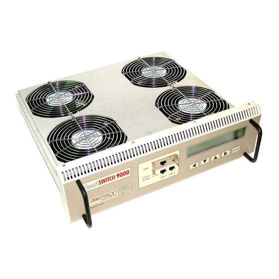
9C300-1 Environmental Module Operation The 9C300-1 Environmental Module, as shown in Figure 3-1, performs three main functions. It monitors several chassis environmental parameters, provides multiple out-of-band management interfaces, as well as system cooling. The Environmental Module also includes LANVIEW diagnostics. MMAC Monitoring Functions The 9C300-1 Environmental Module monitors the following MMAC-Plus... -
Page 14: External Ambient Temperature
9C300-1 Environmental Module Operation External Ambient Temperature The 9C300-1 Environmental Module includes an external ambient temperature sensor. This sensor is located on the front of the Environmental Module, as shown in Figure 3-2. The ambient temperature is monitored and the results of the monitoring are available to the network manager via the LCD, as well as local and remote management. -
Page 15: Fan Speed
Fan Speed The 9C300-1 Environmental Module adjusts the speed of the system cooling fans (Figure 3-3) based on the external ambient temperature. Fan speed increases as ambient temperature rises to ensure adequate cooling for the system. Conversely, fan speed decreases as ambient temperature decreases. In the event the ambient temperature sensor, or the Environmental Module itself, fails, fan speed defaults to maximum speed to ensure adequate cooling. -
Page 16: System Humidity
9C300-1 Environmental Module Operation System Humidity The 9C300-1 Environmental Module monitors the non-condensing humidity level of the MMAC-Plus. The results of the monitoring are available to the network manager via LCD, as well as local and remote management. The humidity levels are displayed as shown in Table 3-2. -
Page 17: Lanview Leds
LANVIEW LEDs The LANVIEW LEDs on the front of the 9C300-1 Environmental Module may be used as an aid in troubleshooting. There are two LEDs visible to the user (Figure 3-4): the STATUS LED and the ALARM LED. Figure 3-4. 9C300-1 Environmental Module LANVIEW LEDs The STATUS LED indicates the current status of the Environmental Module processor and peripherals. -
Page 18: Out-Of-Band Management
9C300-1 Environmental Module Operation The ALARM LED indicates the presence, or absence, of an unread system alarm(s). Unread system alarms can be read using the LCD and five-function keypad. The possible states and descriptions of the ALARM LED are listed in Table 3-5. -
Page 19: Com1 And Com2 Ports
COM1 and COM2 Ports The 9C300-1 Environmental Module front panel has two RJ-45 communication ports for RS-232 serial communication to and from the MMAC-Plus. Figure 3-5 illustrates a single RJ-45 communication port connector. COM1 and COM2 can be configured to run the Serial Line Internet Protocol (SLIP), Point-to-Point Protocol (PPP), Local Management via a terminal or modem connection, or monitor an American Power Conversion Smart UPS. -
Page 20: The Ethernet™ Port Interface Module (Epim)
9C300-1 Environmental Module Operation The Ethernet™ Port Interface Module (EPIM) The 9C300-1 Environmental Module provides a port for Cabletron Systems EPIMs. The EPIM provides a direct connection to the internal SMB-10 bus. This connection can be used for out-of-band graphical SNMP management of the MMAC-Plus system or a Telnet session into local management. -
Page 21: Non-Interactive Mode
Non-Interactive Mode The LCD defaults to this mode if there is no user input within 60 seconds of installation of the Environmental Module or system start-up. Non-Interactive Mode Screens This section describes the LCD screens that display in the non-interactive mode. The LCD scrolls through different status screens (depending on MMAC-Plus configuration), displaying each screen for a period of 7 seconds;... -
Page 22: The Utilization Screen
9C300-1 Environmental Module Operation The Utilization Screen The Utilization Screen, as shown in Figure 3-8, is the second screen of the non-interactive mode. Line 1 displays the screen heading. Line 2 displays the FDDI 1 and FDDI 2 bus utilization. Line 3 displays the INB A and INB B bus utilization. -
Page 23: The Power Screen
CHASSIS POWER POWER LOAD_ _ _ _ _ _ _ _ _ _ 100% POWER REDUNDANCY AVAILABLE SYSTEM STATUS NORMAL Figure 3-10. The Power Screen CABLETRON SYSTEMS INC. MMAC-PLUS SYSTEM UPTIME hh:mm:ss SYSTEM STATUS NORMAL Figure 3-11. The System Banner Screen... -
Page 24: Interactive Mode
9C300-1 Environmental Module Operation Interactive Mode The LCD enters this mode upon installation. This mode allows user input through the five-function keypad to navigate through MMAC-Plus status screens, and to make menu selections. Press any button on the keypad to enter this mode from the non-interactive mode. Once past the Main screen, the Interactive Mode is maintained for three minutes without a keypad entry before returning to the non-interactive mode. -
Page 25: The Main Screen
Lines 2 and 3 show the description of the current alarm including the module and parameter(s) causing the alarm. If other alarms are in the queue (indicated by x > 1 on line 1), select <MORE> to see the information screens for them. CABLETRON SYSTEMS INC MMAC-PLUS <ALARMS> Figure 3-13. The Main Screen... -
Page 26: The System Screen
9C300-1 Environmental Module Operation Select <ACKNOWLEDGE> after reading all alarms to reset the front panel ALARM LED (red to green). Selecting <ACKNOWLEDGE> deletes all alarms and resets the alarm pending banner on line 4 of the non-interactive screens. Select <EXIT> to return to the Main Screen. The System Screen Select the <SYSTEM>... -
Page 27: The Power Screen
The Power Screen Select <PWR> from the System Screen, as shown in Figure 3-15, to access information about the chassis power supply configuration. Line 1 of the Power Screen, as shown in Figure 3-16, displays the number of power supplies currently configured and the availability of power redundancy. Lines 2 and 3 display the power supply status as either ON, OFF DUE TO MANAGEMENT, or FAULT. -
Page 28: The Environment Screen
9C300-1 Environmental Module Operation The Environment Screen Select <ENV> from the System Screen, as shown in Figure 3-15, to view environmental parameters of the MMAC-Plus. Line 1 of this screen, as shown in Figure 3-18, displays the external temperature of the current chassis in both Fahrenheit and Celsius, and qualifies the temperature as COLD, COOL, NORM (normal), WARM, or HOT, based on system parameters. -
Page 29: The Diagnostic Module Selection Screen
The Diagnostic Module Selection Screen Select <DIAGS> from the System Screen, as shown in Figure 3-15, to view the Diagnostic Module Selection screen. Line 1, as shown in Figure 3-20, displays the screen heading. Lines 2 and 3 show the chassis slot locations in which modules have been installed in the MMAC-Plus. -
Page 30: The Bbu Screen
9C300-1 Environmental Module Operation The BBU Screen Select <BBU> from the System Screen, as shown in Figure 3-15, to view the status of the Battery Backup Units (BBUs). Figure 3-22 shows the BBU Screen. Line 1 displays the screen heading. Line 2 displays BBU status (CHARGING, STANDBY or DISCHARGING) if BBUs are installed;... -
Page 31: The Module Specific Screen
The Module Specific Screen Select a module on the Module Selection Screen, as shown in Figure 3-23, to display configuration information on the Module Specific Screen, as shown in Figure 3-24. Line 1 identifies the selected module by chassis slot location, current status, and hardware revision. -
Page 32: The Module Environment Screen
9C300-1 Environmental Module Operation The Module Environment Screen Select <ENV> at the Module Specific Screen, as shown in Figure 3-24, to display environmental parameters for the specific module. Line 1 of the Module Environment Screen, as shown in Figure 3-25, identifies the selected module by chassis slot location. -
Page 33: The Module Backplane Screen
The Module Backplane Screen Select <BACKPLANE> on the Module Specific Screen, as shown in Figure 3-24, to access the Module Backplane Screen, as shown in Figure 3-27. The Module Backplane Screen displays the current MMAC-Plus backplane configuration for a selected module. Line 1 identifies the selected module by chassis slot location. -
Page 34: The Environmental Module Environment Screen
9C300-1 Environmental Module Operation The Environmental Module Environment Screen Select <ENV> on the Environmental Module Specific Screen, as shown in Figure 3-28, to access the Environmental Module Environment Screen, as shown in Figure 3-29. This screen displays voltage, temperature, and non-condensing humidity readings for the Environmental Module. -
Page 35: The Lcd Contrast Adjustment Screen
The LCD Contrast Adjustment Screen Select <SCREEN CONTRAST> from the Main Screen, as shown in Figure 3-13, to access the LCD Contrast Adjustment Screen, as shown in Figure 3-30. Select <LIGHTER> and press ENTER (repeat as necessary) to make the displayed characters appear lighter on the screen. - Page 36 9C300-1 Environmental Module Operation 3-24...
-
Page 37: Chapter 4 Specifications
Specifications Safety It is the responsibility of the person who sells the system to which the modules will be a part to ensure that the total system meets allowed limits of conducted and radiated emissions. CAUTION The 9C300-1 Environmental Module, when properly installed in the MMAC-Plus chassis, complies with the following safety specifications and standards. -
Page 38: Physical
Specifications Physical Dimensions 12.7 H x 43.2 W x 44.5 D centimeters (5 H x 17 W x 17.5 D inches) Weight Unit: Shipping: Environmental Operating Temperature: Operating Humidity: Cooling: 6.5 kilograms (14 pounds) 7.7 kilograms (17 pounds) 5–40 C, 43–100 F 5% to 95% non-condensing 21.8 cubic meters of air per minute drawn through the chassis... -
Page 39: Appendix A Epim Specifications
Introduction The 9C300-1 Environmental Module provides a port for Cabletron Systems EPIMs. EPIMs let you connect to the main network using different media types. Cabletron Systems offers a variety of EPIMs whose specifications are explained in the following sections. EPIM-T The EPIM-T is an RJ-45 connector supporting UTP cabling. -
Page 40: Epim-F1 And Epim-F2
EPIM-F1 and EPIM-F2 The EPIM-F1 and EPIM-F2 support Multimode Fiber Optic cabling. Each EPIM has an internal Cabletron Systems FOT-F™ Fiber Optic Transceiver. The EPIM-F1 is equipped with SMA Connectors and the EPIM-F2 is equipped with ST Connectors. Figure A-2 shows both EPIMs. Specifications for the EPIMs are listed in Table A-1. - Page 41 Parameter 50/125 m -13.0 dBm fiber 62.5/125 m -10.0 dBm fiber 100/140 m -7.0 dBm fiber Error Rate Better than 10 The transmitter power levels and receive sensitivity levels listed are Peak Power Levels after optical overshoot. A Peak Power Meter must be used to correctly NOTE compare the values given above to those measured on any particular port.
-
Page 42: Epim-F3
EPIM-F3 The EPIM-F3 supports Single Mode Fiber Optic cabling. It has an internal Cabletron Systems FOT-F™ Fiber Optic Transceiver and is equipped with ST Connectors. Figure A-3 shows the EPIM-F3. Specifications for the EPIM-F3 are listed in Figure A-4 and Table A-3. - Page 43 Parameter Transmitter Peak Wave Length Spectral Width Rise Time Fall Time Duty Cycle Bit Error Rate The transmitter power levels given above are Peak Power Levels after optical overshoot. You must use a Peak Power Meter to correctly compare the values NOTE given above to those measured on any particular port.
-
Page 44: Epim-C
EPIM-C The EPIM-C supports thin-net coaxial cabling and is equipped with an internal Cabletron Systems TMS-3™ Transceiver. You can use the TERM switch on the front of the EPIM-C to set the internal 50-ohm terminator. This eliminates the need to connect the port to a tee-connector and terminator. Figure A-5 shows the setting for the terminator switch. -
Page 45: Epim-A And Epim-X (Aui Port
EPIM-A and EPIM-X (AUI Port) The EPIM-A is a DB-15 female connector used to attach segments to an external transceiver. The EPIM-X is equipped with dual internal transceivers. It has a DB-15 male connector used to attach segments to an AUI cable. Figure A-6 shows both modules. - Page 46 EPIM Specifications...
-
Page 47: Appendix B Uninterruptible Power Supply (Ups)
Uninterruptible Power Supply (UPS) Introduction The MMAC-Plus can be connected to a UPS to provide an uninterruptible source of AC power. Two UPS models are available, the Matrix 3000 and the Matrix 5000. Either can be monitored via remote SNMP Management after connecting the UPS to the Environmental Module (EM). -
Page 48: Configuring Com Port For Ups
Uninterruptible Power Supply (UPS) MMAC 9C3001 MMAC-Plus Chassis (Front View) Configuring COM Port for UPS After the UPS has been connected to the COM2 port, the COM2 port must be configured for UPS Management. To configure the COM2 port for UPS Management, follow the steps below. -
Page 49: Verifying Configuration
Verifying Configuration After configuring the COM port for a UPS, verify the configuration was done correctly by checking the Communications Screen on the EM. Follow the steps below to verify the configuration. At the Main Screen select <SYSTEM> and press ENTER. At the System Screen select <COM>... - Page 50 Uninterruptible Power Supply (UPS)
Need help?
Do you have a question about the Environmental Module TM 9C300-1 and is the answer not in the manual?
Questions and answers