
Related Manuals for Cabletron Systems TPMIM-22


Summary of Contents for Cabletron Systems TPMIM-22
-
Page 1: Installation Guide
10BASE-T TWISTED PAIR MEDIA INTERFACE MODULE (TPMIM-22/24/32/34) INSTALLATION GUIDE INC. The Complete Networking Solution CABLETRON SYSTEMS, P.O. Box 5005, Rochester, NH 03867-5005... - Page 2 Printed in the United States of America Order number: 9030424 Apr. 91 LANVIEW is a registered trademark of Cabletron Systems, Inc. SPECTRUM, Remote LANVIEW/Windows, TPMIM-22, TPMIM-24, TPMIM-32, TPMIM-34, MMAC-8, MMAC-8FNB, MMAC-5FNB, MMAC-3, MMAC-3FNB, PSM-R, MMAC-5PSM, IRM-2, IRBM, TPT and LAN-MD are trademarks of...
-
Page 3: Fcc Notice
FCC NOTICE This device complies with Part 15 of FCC rules. Operation is subject to the following two conditions: (1) this device may not cause harmful interference, and (2) this device must accept any interference received, including interference that may cause undesired operation. WARNING: This equipment uses and generates and can radiate radio frequency energy and if not installed properly and used in accordance with the instruction manual, may cause interference to radio communications. -
Page 4: Table Of Contents
CHAPTER 1 - INTRODUCTION 1.1 Using This Manual ... 1-1 1.2 Getting Help ... 1-2 1.3 The 10BASE-T Twisted Pair Media Interface Modules... 1-3 1.3.1 The TPMIM-22/24... 1-4 1.3.2 The TPMIM-32/34... 1-4 1.4 Related Manuals ... 1-4 CHAPTER 2 - NETWORK REQUIREMENTS/SPECIFICATIONS 2.1 Network Requirements ... -
Page 5: Chapter 1 - Introduction
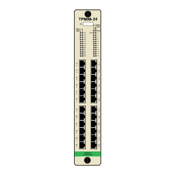
Cabletron Systems offers four versions of the 10BASE-T Twisted Pair Media In- terface Module (Fig. 1-1) for connecting 10BASE-T Twisted Pair Segments to a Multi Media Access Center (MMAC™): • TPMIM-22 with 12 RJ-45 ports. • TPMIM-24 with 24 RJ-45 ports. •... - Page 6 INTRODUCTION Figure 1-1. 10BASE-T Twisted Pair Media Interface Modules Page 1-2...
-
Page 7: Getting Help
INTRODUCTION Chapter 4, Testing and Troubleshooting, provides procedures for testing and troubleshooting the installation of the TPMIM. Instructions for using LAN- ® VIEW , Cabletron Systems’ built-in visual diagnostic and status monitoring sys- tem, are also included. We assume that you have a general working knowledge of Ethernet or IEEE 802.3 type data communications networks and their physical layer components. - Page 8 INTRODUCTION Polarity Detection and Correction Each Port on the TPMIM incorporates a Polarity Detection and Correction fea- ture. The Polarity Detection and Correction feature allows the TPMIM to pass data regardless of the polarity of the twisted pair segments’ receive link. If polar- ity is reversed, the LNK LED will flash to indicate this condition, once a good packet passes through the port.
-
Page 9: Lanview Leds
The TPMIM-22/24 design incorporates built-in RJ-45 ports, 12 on the TPMIM- 22 and 24 on the TPMIM-24. This design makes it easier to incorporate twisted pair wiring schemes into your network. The TPMIM-22/24 allows you to directly connect the segments to patch panels or other 10BASE-T Ethernet devices, elim- inating the need for Punch-Down blocks or additional patch panels. -
Page 10: The Tpmim-32/34
INTRODUCTION 1.3.2The TPMIM-32/34 The TPMIM-32/34 provides an alternative method for incorporating 10BASE-T twisted pair segments into an existing twisted pair wiring scheme. The TPMIM- 32 has one 50 pin Champ connector that allows you to connect 12 segments to the module. -
Page 11: Installation Requirements/Specifications
INSTALLATION REQUIREMENTS/SPECIFICATIONS Before you attempt to install the Cabletron Systems 10BASE-T Twisted Pair Me- dia Interface Modules, review the network requirements that are outlined in this chapter. Also, refer to the operating specifications that are listed. All conditions, guidelines, specifications, and requirements included in this chap- ter must be met to ensure satisfactory performance of the TPMIM. - Page 12 • Insertion Loss - The maximum insertion loss allowed for a 10BASE-T link is 11.5 dB at all frequencies between 5.0 and 10.0 MHz. This includes the attenuation of the cables, connectors, patch panels, and reflection losses due to impedance mismatches in the link segment. •...
-
Page 13: Operating Specifications
The operating specifications for the Cabletron Systems TPMIM are included in this section. Cabletron Systems reserves the right to change these specifications at any time without notice. RJ-45 INTERFACE (TPMIM-22/24) Internal Transceiver:Cabletron Systems’ TPT 10BASE-T Twisted Pair Transceiver. Type:Internally Crossed Over RJ-45 Jack No Connection REQUIREMENTS/SPECS. - Page 14 CHAMP CONNECTOR INTERFACE (TPMIM-32/34) Type: Signal RX 1- Blue/White TX 1- Orange/White RX 2- Green/White TX 2- Brown/White RX 3- Gray/White TX 3- Blue/Red RX 4- Orange/Red TX 4- Green/Red RX 5- Brown/Red TX 5- Gray/Red RX 6- Blue/Black TX 6- Orange/Black RX 7- Green/Black...
-
Page 15: Front Panel Indicators
FRONT PANEL INDICATORS (Collision Present) of the segments ERR (Error) NOTE: There is one Link and Receive LED for each port on the module. LNK (Link) RCV (Receive) ENVIRONMENTAL REQUIREMENTS Operating temperature:+5 to +40 C (41 to 104 F) Non operating temperature:-30 to +80 C (-22 to 160 F) Operating humidity:5 to 95% (non-condensing) REQUIREMENTS/SPECS. - Page 16 TPMIM will be a part to ensure that the total system meets allowed limits of conducted and radiated emissions. Designed in accordance with UL478, UL910, NEC 725-2(b), CSA, IEC, TUV, VDE Class A. Meets FCC part 15, Class A limits. SERVICE MTBF (MHBK-217E) TPMIM-22 TPMIM-24 TPMIM-32 TPMIM-34 MTTR<0.5 hr. PHYSICAL...
-
Page 17: Unpacking The Tpmim
INSTALLING THE TPMIM This chapter contains instructions for installing the Cabletron Systems 10BASE- T Twisted Pair Media Interface Module (TPMIM) into any of Cabletron Systems' MMACs. Instructions for connecting twisted pair segments to the MIM are also included. Check that all requirements listed in Chapter 2, Installation Require- ments/Specifications, are met before installing the MIM. - Page 18 • If installing a TPMIM-24/34, an IRM-2 or an IRBM must be installed Slot • If the module is going to be installed into an MMAC-8™/MMAC-8FNB™/MMAC-5FNB™, be sure a Power Supply Module (PSM-R™, or MMAC-5PSM™) is installed in the MMAC to supply power to the module.
-
Page 19: Connecting The Tpmim To The Network
MMAC. 3.3.1 Attaching Twisted Pair Segments to the TPMIM-22/24 The TPMIM-22 has 12 RJ-45 ports, while the TPMIM-24 has 24 RJ-45 ports. This provides easy connection of unshielded twisted pair segments to the MIM. Each port on the module is internally crossed over. This is indicated by an X next to the port. -
Page 20: Attaching Twisted Pair Segments To The Tpmim-32/34
Pin 6 - TX- Pin 7 - N/C Pin 8 - N/C Figure 3-2. Cable Pinouts - TPMIM-22/24 3.3.2 Attaching Twisted Pair Segments to the TPMIM-32/34 The TPMIM-32 has a 50 pin Champ connector, while the TPMIM-34 has two 50- pin Champ connectors. - Page 21 As an aid, three tables and one figure have been included with this section. Table 3-1 describes the pins and the color codes that are used in twisted wiring from the TPMIM-32/34 and a punch down block. Table 3-2 describes the pins and the col- or codes that are used from a punch down block to a 10BASE-T Ethernet device.
- Page 22 If the Link LED is flashing, once a good packet passes through the port, this indi- cates that the polarity of the twisted pair segments’ receive link is reversed. If this condition exists, the segment should be removed from the TPMIM and the wiring corrected in the event that, in the future, the segment needs to be attached to a de- vice without the Polarity Correction and Detection feature.
- Page 23 Port 9/21 RX+ Pin 42 Pin 17 Pin 43 Pin 18 INSTALLING THE TPMIM Yellow/Orange RX+ A33 Yellow/Orange Orange/Yellow Yellow/Green Green/Yellow A34 Orange/Yellow A35 Yellow/GreenTX+ A36 Green/Yellow Page 3-7...
- Page 24 FROM A TPMIM-32/34 TO A PUNCH DOWN BLOCK From Into and Out of 50 Into Punchdown TPMIM-32/34Pin Feeder CableBlock Port 8/20 RX+ Pin 40 Pin 15 Pin 41 Pin 16 Port 7/19 RX+ Pin 38 Pin 13 Pin 39 Pin 14 Port 6/18 RX+ Pin 36 Pin 11...
- Page 25 Port 4/16 RX+ Pin 32 Pin 7 Pin 33 Pin 8 INSTALLING THE TPMIM Red/Orange A13 Red/OrangeRX+ Orange/Red A14 Orange/RedRX- Red/Green A15 Red/GreenTX+ Green/Red A16 Green/RedTX Page 3-9...
- Page 26 FROM A TPMIM-32/34 TO A PUNCH DOWN BLOCK From Into and Out of 50 Into Punchdown TPMIM-32/34Pin Feeder CableBlock Port 3/15Pin RX+ Pin 30 Pin 5 Pin 31 TX- Pin 6 6 Blue/RedTX- Port 2/14Pin RX+ Pin 28 Pin 3 Pin 29 Pin 4 Port 1/13Pin...
- Page 27 FROM A PUNCH DOWN BLOCK TO A 10BASE-T DEVICE From PunchdownTo RJ-45Into Office Into BlockWallplate Port 12/24PinPin Violet/Green Green/Violet Violet/Brown Brown/Violet Port 11/23 Violet/Blue Blue/Violet Violet/Orange Orange/Violet Port 10/22 Pin Yellow/Brown Brown/Yellow Yellow/Gray Gray/Yellow Port 9/21 Yellow/Orange Orange/Yellow Yellow/Green Green/Yellow Port 8/20 Black/Gray Gray/Black...
- Page 28 FROM A PUNCH DOWN BLOCK TO A 10BASE-T DEVICE From PunchdownTo RJ-45Into Office Into BlockWallplate Port 7/19 Black/Green Green/Black Black/Brown Brown/Black Port 6/18 Black/Blue Blue/Black Black/Orange Orange/Black Port 5/17 Red/Brown Brown/Red Red/Gray Gray/Red Port 4/16 Red/Orange Orange/Red Red/Green Green/Red INSTALLING THE TPMIM TABLE 3-2 (cont.) TWISTED PAIRS WIRING Drop 10BASE-T...
- Page 29 FROM A PUNCH DOWN BLOCK TO A 10BASE-T DEVICE From PunchdownTo RJ-45Into Office Into BlockWallplate Port 3/15 White/Gray Gray/White Red/Blue Blue/Red Port 2/14 White/Green Green/White White/Brown Brown/White Port 1/13 White/Blue Blue/White White/Orange Orange/White INSTALLING THE TPMIM TABLE 3-2 (cont.) TWISTED PAIRS WIRING Drop Pin Pin Pin Pin...
- Page 30 TWISTED PAIR WIRING SUMMARY TPMIM 32/34Punch DownWall Plate ChampBlock (If Required) INSTALLING THE TPMIM TABLE 3-3 10BASE-T Ethernet Device Page 3-14...
- Page 31 Port 12 48 RX+ A45 RX+ 23 RX- A46 RX- 25 Pin Feeder 49 TX+ Cable A47 TX+ 24 TX- A48 TX- Port 11 46 RX+ A41 RX+ 21 RX- A42 RX- 25 Pin Feeder Cable 47 TX+ A43 TX+ 22 TX- A44 TX- Port 1...
- Page 32 INSTALLING THE TPMIM Page 3-17...
-
Page 33: Chapter 4 - Testing And Lanview
CHAPTER 4 TESTING AND LANVIEW This section contains procedures to ensure that the connection between the TP- MIM and the 10BASE-T Ethernet device is functioning properly. A description of LANVIEW and its function in troubleshooting physical layer network prob- lems is also provided. INSTALLATION CHECK-OUT You should test the TPMIM after installation to ensure that the physical layer of the network is operating properly. - Page 34 LAN-MD Segment AUI Cable Twisted Pair Segment MMAC-8 Figure 4-1. Sample Installation Check-Out Configuration 6. Using another transceiver (7) and AUI cable (8), connect another LAN-MD (9) to any other tested segment that is connected to an MMAC. 7. Select and run test 4 - NODE on the LAN-MD connected in step 6. Verify that this test passes.
-
Page 35: Using Lanview
TESTING AND LANVIEW 4.2 USING LANVIEW The TPMIM uses Cabletron Systems built-in visual diagnostic and status moni- toring system, LANVIEW. Using LANVIEW LEDs, your network troubleshoot- ing personnel can quickly scan the LEDs to observe network status or diagnose network problems, and determine which node or segment is faulty. The following section discusses the function and the purpose of each LANVIEW LED on the TPMIM. - Page 36 TESTING AND LANVIEW LINK OK (LNK) When lit, this green LED indicates that a link has been established between the TPMIM and the 10BASE-T device at the other end of the twisted pair segment. This LED remains lit as long as the link is maintained. If no data has been sent for 16 msec, a positive link test pulse of 100 nsec is sent onto the transmit link of the twisted pair cable.
Need help?
Do you have a question about the TPMIM-22 and is the answer not in the manual?
Questions and answers