
Related Manuals for Cabletron Systems 1082


Summary of Contents for Cabletron Systems 1082
- Page 1 SPECTRUM Enterprise Manager Device Management SmartSwitch 6000 Supports Management Modules SM-CSI1076, 1082, 1088...
- Page 2 Notice Cabletron Systems reserves the right to make changes in specifications and other information contained in this document without prior notice. The reader should in all cases consult Cabletron Systems to determine whether any such changes have been made. The hardware, firmware, or software described in this manual is subject to change without notice.
-
Page 3: Table Of Contents
INTRODUCTION Purpose and Scope ...7 Required Reading ...7 Supported Devices...8 Networking Characteristics...8 Management Modes...9 Distributed Mode...9 Standalone Mode...9 Mixed Mode ...9 6C105 Chassis ...10 SmartSwitch 6000 Modules...11 6E Ethernet Modules ...11 6H Fast Ethernet Modules ...12 6M146-04 Carrier Module ...12 The SPECTRUM Model ...12 Views Summary ...14 TASKS... - Page 4 C o n t e n t s Repeater Port Performance View ...20 DEVICE VIEWS Chassis Device View ...21 Chassis Module Icon ...22 Module Identification Labels ...23 Module Icon Subviews...23 Application Label ...24 Interface Labels ...25 Repeater Labels ...26 Repeater Frame & Error Breakdown View...27 Repeater Frame Size &...
- Page 5 C o n t e n t s MODELING Introduction ...61 AutoDiscovery vs. Manual Modeling ...61 Manual Modeling Overview...62 Container View...62 Preparation for Modeling...63 Modeling Using the Chassis IP ...63 New Model By IP Option ...65 Positioning the Chassis Device Icon ...66 INDEX S P E C T R U M E n t e r p r i s e M a n a g e r Page 6...
-
Page 6: Introduction
This section introduces SPECTRUM Device Management documentation for SmartSwitch 6000 devices. The section is organized as follows: • Purpose and Scope • Required Reading • Supported Devices (page 8) • The SPECTRUM Model (page 12) Purpose and Scope Use this documentation as a guide for managing SmartSwitch 6000 devices with the SPECTRUM management modules SM-CSI1076, SM-CSI1082, and SM-CSI1088. -
Page 7: Supported Devices
I n t r o d u c t i o n Supported Devices The SPECTRUM management modules SM-1076, SM-1082, SM-1088 currently allow you to model the following Chassis and SmartSwitch 6000 devices: • The 6C105 Chassis (page modular chassis that can incorporate two load sharing power supplies and up to five SmartSwitch 6000 modules. -
Page 8: Management Modes
I n t r o d u c t i o n Management Modes You can configure the SmartSwitch 6000 to operate in three management modes: Distributed, Standalone, and Mixed. Refer to the appropriate SmartSwitch 6000 module user’s guides for instructions on configuring the modules Note: Note:... -
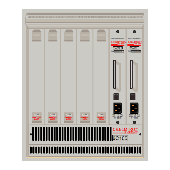
Page 9: 6C105 Chassis
S p e c t r u m E n t e r p r i s e M a n a g e r Figure 1: SmartSwitch 6000 Chassis Smart Smart Smart SWITCH SWITCH SWITCH 6000 6000 6000... -
Page 10: Smartswitch 6000 Modules
I n t r o d u c t i o n SmartSwitch 6000 Modules The modules are divided into three groups representing three technologies: Ethernet, Fast Ethernet, and Carrier. The groups are supported by SPECTRUM Management Module products as listed in Table Table 1: SPECTRUM Products... -
Page 11: 6H Fast Ethernet Modules
I n t r o d u c t i o n 6H Fast Ethernet Modules These modules provide the front panel ports and interface uplink connectivities listed in Table 3: 6H Series Connectivities Module Connectivity 6H122-08 Six 10/100Base-TX ports via RJ45s plus two FEPIM slots 6H122-16 16 10/100Base-TX ports via Cat 5 RJ45... - Page 12 I n t r o d u c t i o n attributes and functionality. Refer to (page 61) for modeling instructions. The model type designators for the SmartSwitch 6000 use an underbar to replace the dash in the device model number. For example, 6E122_26 refers to the model type for the 6E122-26 module.
-
Page 13: Views Summary
I n t r o d u c t i o n Views Summary Device icons provide access to views, subviews, and tables that let you manage the modeled device. Figure 2 shows a general example of the Icon Subviews menu for a Device icon. The views listed below are accessible directly from this menu and are described individually in subsequent sections of this documentation. -
Page 14: Tasks
T a s k s This section identifies various management and troubleshooting tasks that can be performed for the SmartSwitch 6000 using the views, icons, and labels referenced within this document. Advertised Ability (Check) • Advertised Ability (page 55) Alarm Thresholds (Set) •... -
Page 15: Fddi Operation (Check)
T a s k s FDDI Operation (Check) • FddiMAC Device Configuration View (page 49) • The current operational mode of this port. FDDI MAC Application (page 41) Firmware (Upgrade) • Download Application (page 46) Model a SmartSwitch 6000 • Modeling (page 61) •... -
Page 16: Repeater Port Speed (Set)
T a s k s Repeater Port Speed (Set) • Repeater Port Labels (page 28) Repeater Port Condition Display (Change) • Repeater Port Display Form (page 27) Topology (Check) • Device Topology View (page 37) Traps (Set Up) • Device Configuration View (page 47) •... -
Page 17: Performance Views
P e r f o r m a n c e V i e w s This section provides brief descriptions of Performance views available for models of SmartSwitch 6000 devices in SPECTRUM. Performance views provide statistical information about the operation of the device and packet information for the device and its ports. -
Page 18: Device Performance View
P e r f o r m a n c e V i e w s Device Performance View Access: From the Icon Subviews menu for the SmartSwitch 6000 Device icon, select Performance. This view (Figure 3) provides the following current and historical frame transmission statistics for the device: •... -
Page 19: Repeater Port Performance View
P e r f o r m a n c e V i e w s Repeater Port Performance View Access: From the Chassis Module icon, select Repeater Label, Repeater Performance. This view provides the following current, average, peak frame rate and error statistics for repeater ports on the 6E123-50, 6E133-49, 6H123-50, and 6H133-37 modules: •... -
Page 20: Device Views
D e v i c e V i e w s This section describes the Device views and subviews available for models of SmartSwitch 6000 devices in SPECTRUM. Device views use icons and labels to represent the modeled device and its components, such as modules, ports, and applications. -
Page 21: Chassis Module Icon
D e v i c e V i e w s Chassis Module Icon This icon is a logical representation of the physical module, its location in the chassis, its front panel interfaces and ports. Figure 5 shows an example of a Chassis Module icon. -
Page 22: Module Identification Labels
D e v i c e V i e w s Module Identification Labels These labels provide the information described below (see Figure Slot Number The module’s location in the chassis. Double-click this label to open the Application view described under Applications View (page Model Type... -
Page 23: Application Label
D e v i c e V i e w s Application Label This label displays the application currently selected, which is either Bridging, 802.1Q, or Physical. Bridging is the default application. To change the application, highlight the Chassis Module icon and select View > Icon Subviews > Application Display. -
Page 24: Interface Labels
D e v i c e V i e w s Interface Labels These labels represent the interfaces located on the front panel of the module. Each label provides access to an Icon Subviews menu, which contains the following three device-specific selections: •... -
Page 25: Repeater Labels
D e v i c e V i e w s Repeater Labels The 6E123-50, 6E133-49, 6H123-50, and 6H133- 37 modules have repeater ports. The repeater ports on the 6E123-50 and 6E133-49 have a fixed port speed of 10Mb while those on the 6H123-50 and 6H133-37 can be switched between 10 Mb and 100 Mb. -
Page 26: Repeater Frame & Error Breakdown View
D e v i c e V i e w s Repeater Frame & Error Breakdown View This view displays frame and error statistical information for a selected repeater port. The statistics are displayed in the form of pie charts and tables. -
Page 27: Repeater Port Labels
D e v i c e V i e w s you select Admin via the E1 Repeater label, the Repeater Port labels associated with E1 (i.e., Ports 1 through 12) will display the administrative status. Repeater Port Labels The 6E123-50 and 6E133-49 modules have 10 Mb repeater ports while the 6H123-50 and 6H133-37 modules have the capability of switching ports between 10 Mb and 100 Mb... -
Page 28: Chassis Information
D e v i c e V i e w s Chassis Information This area of the Chassis Device view provides information for the chassis power modules and cooling fans. Figure 6 shows the Chassis Information fields as displayed in the Chassis Device view. -
Page 29: Interface Device View
D e v i c e V i e w s Interface Device View Access: From the Icon Subviews menu of the SmartSwitch 6000, select Device > Interface. This view (Figure 7) provides dynamic configuration and performance information for each of the device’s serial/network I/O ports, which are represented by Interface icon in the bottom panel of the view, as shown in The middle panel of the view also displays a... -
Page 30: Interface Icon
D e v i c e V i e w s Interface Icon This icon is a logical representation of a network interface or port, see Interface Device View (page 30). Figure 8 shows a sample Interface icon, its labels and double-click zones. Figure 8: Network Interface Module Icon Interface Icon Subviews Menu ( a ) -
Page 31: Backplane Device View
D e v i c e V i e w s default application for this view is Physical (MIB- II). To select the application to be displayed (Physical or Bridging), click the Filter menu button in the Interface Options panel. This label provides double-click access to - CSIIfPort View (page 49). - Page 32 D e v i c e V i e w s for each of the modules installed in the chassis, see, Backplane Module Icon (page The Backplane Device view also contains a Chassis Information panel, which shows the same information as a similar panel on the Chassis Device view, see Chassis Information, Chassis Information (page 29).
-
Page 33: Backplane Module Icon
D e v i c e V i e w s Backplane Module Icon Figure 10 shows a sample Backplane Module icon, which displays in the Backplane Device view. This icon represents the physical module, its location in the chassis, and its backplane interfaces. -
Page 34: Module Identification Labels
D e v i c e V i e w s Module Identification Labels These labels provide the following information that identifies a specific device. Slot Number The module’s location in the chassis. Double-click this area to open the Application view described under Applications View (page Model Type... -
Page 35: Physical Device View
6E132-25 PDK 0 0 REDUNDANCY CaBLeTROn SYST 6C205-1 B0096520019 100 • 125 VAC Smart Smart Smart Smart Smart 200 • 250 VAC SWITCH SWITCH SWITCH SWITCH SWITCH 50 • 60 Hz 6000 6000 6000 6000 6000 CaBLeTROn 6C105 S m a r t S w i t c h 6 0 0 0... -
Page 36: Device Topology View
D e v i c e T o p o l o g y V i e w Device Topology View This section provides brief descriptions of the Device Topology views available for models of SmartSwitch 6000 devices in SPECTRUM. Access: From the Icon Subviews menu for the SmartSwitch 600 Device icon, select DevTop... -
Page 37: Applications View
A p p l i c a t i o n s V i e w This section describes the Application view and the associated application-specific subviews available for models of SmartSwitch 6000 devices in SPECTRUM. Access: From the Icon Subviews menu for the SmartSwitch 6000 Device icon, select Application. -
Page 38: Application Icons
A p p l i c a t i o n s V i e w Application Icons When the Application view is in Icon mode, each of the application models is represented by an Application icon (Figure 14). Double-clicking the Model Name label (a) at the top of the icon opens the associated Model Information Information View (page... -
Page 39: Supported Applications
A p p l i c a t i o n s V i e w Supported Applications SmartSwitch 6000 devices support both common and device-specific application. Applications that are common to many of the different of kinds of and makes of devices are listed in Table 16 along with their corresponding... -
Page 40: Atm Client Application
A p p l i c a t i o n s V i e w Configuration view carries the Interface, Port Group, and Port information over from this table. Interface The interface number of the port for which this Fast Ethernet information pertains. -
Page 41: Atm Client Application Vcl Table
A p p l i c a t i o n s V i e w Table 18: ATM Client Application Icon Subviews Option Opens the... Configuration Device Configuration View (page Model the Model Information view described in Information SPECTRUM Views. VCL Table ATM Client Application VCL Table described below. - Page 42 A p p l i c a t i o n s V i e w CPCS SDU size in octets that is supported on the transmit direction of this VCC. Receive Size This field is used when the local VCL endpoint is also the VCC endpoint and AAL5 is used.
-
Page 43: Virtual Channel Link View
Remove button, and then the Update button. The row will then be removed from the table view. Double-clicking a field entry opens the interface- specific ATM Switch Application Virtual Channel Link view, which is described below. Virtual Channel Link View... - Page 44 A p p l i c a t i o n s V i e w • Receive Size (for AAL5 connections only) • Encaps Type (for AAL5 connections only) Encaps Type Only exists when the local VCL endpoint is also the VCC endpoint, and AAL5 is in use.
-
Page 45: Csripenetrpt Repeater Application
A p p l i c a t i o n s V i e w CsRipEnetRpt Repeater Application Access: Double-click the CsRipEnetRpt Repeater Application icon. The CsRipEnetRpt supports the 6H123_50, 6E133_49, 6H123_50, and 6H133_37 model types. Table 19 lists all the application-specific subviews available from the Icon subviews menu for this application. -
Page 46: Configuration Views
C o n f i g u r a t i o n V i e w s This section describes the various Configuration views and subviews available for models of SmartSwitch 6000 devices in SPECTRUM. Configuration views (Figure and modify current setting for the modeled device and its interfaces, ports, and applications. -
Page 47: Interface Configuration Table
C o n f i g u r a t i o n V i e w s This view (Figure 15) provides status and configuration information about the device as a whole as well as on a port-by-port basis. Fields and Column heading with the Device Configuration view and its subviews are explained in further detail in the SPECTRUM Views... -
Page 48: Port Configuration - Csiifport View
C o n f i g u r a t i o n V i e w s Port Configuration - CSIIfPort View Access: From the Icon Subviews of the SmartSwitch 6000 Interface Icon, select CSIifPort. This view displays interface-specific MIB information for the module. - Page 49 C o n f i g u r a t i o n V i e w s MAC Address The MAC (physical) address of this station. MAC Count The number of MACs supported by this station. Ring State Isolated The concentrator is not attached to the ring.
- Page 50 C o n f i g u r a t i o n V i e w s Ring State Isolated The port is not inserted into any path. Local_A The A port is inserted into a local path and the B port is not. Local_B The B port is inserted into a local path and the A port is not.
-
Page 51: Smt Information
FDDI SMT: SMT Version The version of Station Management (SMT) running. OBS Present Indicates whether an Optical Bypass Switch (OBS) is connected. T-Notify (sec) The timer value, in seconds, used in Neighbor Notification Protocol. The allowed range is from 2 to 30 seconds. - Page 52 C o n f i g u r a t i o n V i e w s Max VCI (Virtual Channel Identifier) Bits The maximum number of active VCI bits configured for use at this ATM interface. ILMI (Interim Local Management Interface) VPI The VPI value of the VCC supporting the ILMI at this ATM interface.
-
Page 53: Fast Ethernet Configuration View
C o n f i g u r a t i o n V i e w s Fast Ethernet Configuration View Access: Double-Click any entry in the Fast Ethernet Port Table to open this view. This view (Figure 16) lets you configure ports for Ethernet, Fast Ethernet, or Auto-Negotiation. -
Page 54: Advertised Ability
C o n f i g u r a t i o n V i e w s Advertised Ability selections. You can only select one Operational Mode. Table 22 current modes, their values, and descriptions. Table 22: Operational Mode Values Operational Mode Value Auto Negotiation... -
Page 55: Repeater Configuration View
C o n f i g u r a t i o n V i e w s Table 24: Received Technology Values Received Value Technology Undefined Undefined Auto- Auto-Negotiation/Parallel Negotiation Detection Not-Detected Link Partner does not support Auto-Negotiation 10Base-T 10Base-T 10Base-TFD Full duplex 10Base-T... -
Page 56: Trap Configuration
C o n f i g u r a t i o n V i e w s Trap Configuration This area of the Repeater Configuration view allows you to enable or disable the following traps. Link Traps Allows all packets indicating a change in link status to be reported within the trap database. -
Page 57: Error Source
C o n f i g u r a t i o n V i e w s Error Alarms Allows you to enable or disable detection of Error Alarms. Possible menu selections are: Enable and Disable. Error Threshold Displays the threshold value for the percentage of errors per good packet that may occur within the Timebase before generating an error alarm. - Page 58 C o n f i g u r a t i o n V i e w s E t h e r n e t B a s e d C o n f i g u r a t i o n Flow Control The current or desired operational status of the full-duplex flow control on this port.
-
Page 59: Model Information View
M o d e l I n f o r m a t i o n V i e w Model Information View This section provides a brief description of the Model Information view available for the models of SmartSwitch 6000 devices in SPECTRUM. -
Page 60: Modeling
S p e c t r u m E n t e r p r i s e M a n a g e r Modeling Autodiscovery involves manually modeling a seed router, bridge, or switch (if such a model does exist) and then running AutoDiscovery one or more times to complete the network model. You then refine your autodiscovered network model to improve management capabilities. -
Page 61: Manual Modeling Overview
M o d e l i n g For proper device management, the module’s Device icons appear in a Topology view and you may place the chassis’s Device icon in a Room Location view. This is true whether you use AutoDiscovery or manual modeling, In some instances, this may require you to copy and paste Device icons into the proper SPECTRUM views. -
Page 62: Preparation For Modeling
M o d e l i n g Figure 18: Chassis Container View Primary Landscape 0x00400000 - VNM Host - File View Model One Model Two 6E122_26 6E138_25 Model Four Model Five 6H202_24 6H122_16 S p e c t r u m E n t e r p r i s e M a n a g e r Preparation for Modeling Before modeling the chassis, you should be familiar with the process of creating models and... - Page 63 M o d e l i n g Access the Edit mode and select Edit > New Model. The Select Model Type dialog box displays (Figure 19). Figure 19: Select Model Type Dialog Box Select Model Type Building Country Landscape Region Site Filter:...
-
Page 64: New Model By Ip Option
M o d e l i n g Exit the Edit mode and double-click the Building icon to open its Location view. Access the Edit mode and select View > New Model. The Select Model Type dialog box displays. Select Room and then click OK. The Room Creation dialog box displays. -
Page 65: Positioning The Chassis Device Icon
M o d e l i n g See Positioning the Chassis Device Icon, below, to properly locate the automatically created chassis Device icon. Positioning the Chassis Device Icon Some of the modeling procedures described above automatically create a chassis Device icon. This icon can be copied into a Room Location view. -
Page 66: Index
Numerics 6E Series Devices 6H Series Devices 6M146-04 Device Address Type Admin Address Status Administrative Status Advertised Ability Alarm Configuration Info Alignment Applications ATM Channels Information ATM Operation AutoDiscovery S P E C T R U M E n t e r p r i s e M a n a g e r Index Backplane Connection Status... - Page 67 Network Information New Model By IP No_Resource Non Master Ports Non-Op Non-Op, Dup OBS, Present OOW_Colls Oper Status Operation Status Operational Mode Optical Bypass Switch S m a r t S w i t c h 6 0 0 0...
- Page 68 I n d e x Path, Current MAC Performance Statistics Physical Address Physical Application Status Physical Device View Port Configuration Count Enable/Disable Operational Mode Type Ports Master Non Master Operational Power Supply Information Protocol, Neighbor Notification Protocols Received Technology Repeater Configuration View Frames &...
- Page 69 I n d e x Last Change Oper Status Rcv Descr Index Receive Size Remove Row Status RTD Index Transmit Size TTD Index Update Validate Row VCL CC Id Xmit Descr Index VPCs VPI Bits VPI/VCI Configuration Wrap S P E C T R U M E n t e r p r i s e M a n a g e r Page 70 I n d e x S m a r t S w i t c h 6 0 0 0...
Need help?
Do you have a question about the 1082 and is the answer not in the manual?
Questions and answers