
Subscribe to Our Youtube Channel
Related Manuals for Thermo Scientific TCF-32


Summary of Contents for Thermo Scientific TCF-32
- Page 1 Continuous Flow Rotor TCF-32 Instruction Manual english The original copy of this manual is valid. Thermo Scientific cannot guarantee the accuracy or Analyze • Detect • Measure • Control™ completeness of subsequent copies.
-
Page 2: Table Of Contents
CONTENTS 1. PREFACE ································································································································3 2. SPECIFICATIONS·····················································································································3 3. COMPOSITION ·························································································································4 4. USAGE ·································································································································· 11 4.1 General description on usage ························································································· 11 4.2 Usage ·······························································································································12 4.3 Capacity in rotor ·············································································································25 4.4 Determination of sample flow rate····················································································26 4.5 Lubricating unit ············································································································· 26 5. PRECAUTIONS IN USING ROTOR······················································································ 28 6. - Page 3 Precautions on Handling rotor Do not spin a rotor beyond the allowable speed. The maximum speed marked on a rotor refers to an allowable one when the maximum density of the sample or density gradient solution is less than 1.2. When a sample or density gradient solution of more than 1.2 in maximum density is used, the maximum speed must be reduced according to the instruction manual for the rotor.
- Page 4 Do not rotate this rotor at a speed of more than 3,000 rpm unless all components (rotor assembly, seal attachment assembly and lubricating unit assembly) are assembled. Do not rotor at a speed of more than 3,000 rpm unless the rotor is filled with liquid. If the above cautions are not observed, shaft (D) could be broken or the core could be damaged.
-
Page 5: Preface
Supply power for lubricating unit AC 100-240V, 1A (50/60Hz) NOTES For operation of Model TCF-32, the following apparatus are required besides the standard configurations of Model TCF-32 and Preparative Ultracentrifuge, which have to be prepared for installation of Model TCF-32 at customer's site. -
Page 6: Composition
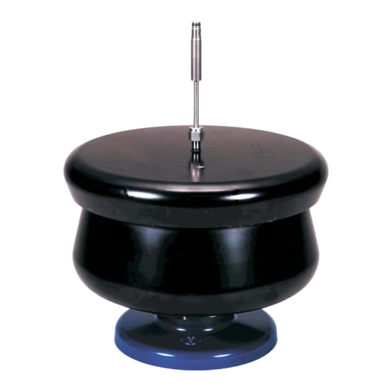
3. COMPOSITION Fig.1 shows the overall construction Oil discharged from bearing is sucked and recovered Lubricating unit Cooling water is Ass’y supplied Lubricant is supplied to bearing Sample inlet Sample outlet Water outlet Seal body ass’y Collar Seal Seal Attachment Door Ass’y Oil inlet... - Page 7 3.1 Rotor body assembly (1) Rotor and cover The rotor and cover are made of titanium alloy which is excellent in mechanical strength and corrosion resistance, and is coated in black (see Fig.2) (2) Core titanium sleeve and blades All of them are introduced in the rotor. The core forms a passage of sample and density gradient solution in the rotor.
- Page 8 (3) Shaft (D) and Swagelok nut The shaft (D) is made of titanium alloy. The section sliding with the bearing is coated with molten tungsten carbide to improve the wear resistance. The Swagelok nut is made of stainless steel. It fastens the shaft (D) on the cover (see Fig. 4) Shaft (D) is a critical component.
- Page 9 3.2 Seal attachment assembly (1) Door adapter It is screwed in the door of the ultracentrifuge, and supports the entire seal attachment (see Fig. 7). (2) Bearing housing The bearing housing holds the bearing made of white metal, and is engaged with the rotor shaft (D).
- Page 10 Seal body ass’y Screw socket (B) Collar Screw socket (A) Fig. 9 Assembly of seal body Fig. 10 Seal body assembly Assembly, collar and Screw sockets 3.3 Lubricating unit assembly The lubricating unit assembly is used when operating this continuous flow rotor. The specification and operation procedure of this unit are as follows.
- Page 11 (2) Function Lubricating unit assembly works as follows. l Supplies lubricating oil to seal attachment assy. l Sucks and recovers waste oil discharged from the bearing housing assembly. l Detects a malfunction when there is trouble in the supply of lubricating oil or cooling water. Fig.11 Lubricating unit l When this safety device activates, solve the problem quickly.
- Page 12 3.4 Tools and accessories Applications of the tools and accessories are enumerated below: Table 2 PARTS NAME a. Rotor base tightens and removes rotor cover b. Handle tightens and removes rotor cover c. Torque wrench installs and removes shaft d. Handle installs and removes door adapter e.
-
Page 13: Usage
4. USAGE 4.1 General description on usage The continuous flow rotor is employed in the following manner : Table 3 Separation procedure Procedure Injection of density Centrifugal separation Recovery gradient solution, buffer Item solution Solution flow Spinning speed 3,000 rpm Specified speed 3,000 rpm Inject high density... -
Page 14: Usage
4.2 Usage Be careful of the following to separate the sample at low temperatures. ¡ Assemble the rotor body assembly and precool it in a low-temperature chamber, etc. ¡ Inject the cooled buffer solution and density gradient solution. ¡ Precool the sample and inject it while cooling the sample container using ice or in a low-temperature chamber, etc. - Page 15 Mount the core, titanium sleeve and blades. O-ring ¡ Make sure the three types of O-ring are f r ee (1AF3) from scratches. Apply a thin coat of vacuum grease on them before installation. Core ¡ Put the blades on the pins on titanium sleeve. ¡...
- Page 16 Mount the rotor on the Rotor base, put on the cover, and tighten by the furnished handle. ¡ Tighten the cover above the match point (see right figure) of the match marks of rotor and cover. Match mark Insert the shaft (D) assembly into the hole located at the center of the cover.
- Page 17 4.2.2 Preparation for spinning Remove the door hole cover of the ultracentrifuge , turn on the POWER switch, and open the door. ¡ To remove the door hole cover, use the door hole adapter handle. Install the rotor gently on the spin shaft. Close the door.
- Page 18 Mount the door adapter. ¡ Use the handle and screw in clockwise to mount. Tighten until the O-ring is compressed enough. ¡ Check that shaft (D) of the rotor is positioned approximately at the center of the center hole of Shaft (D) the door adapter.
- Page 19 Connect the cooling water tube, oil circulation tube and waste oil (drain) to the bearing housing. Refer to the figure below for connections. a. Connect to OIL IN e. Hole for water passage b. Connect to DRAIN IN d. Connect to OIL OUT c.
- Page 20 1) Turn on the OIL switch of the lubricating unit. Lubricant will circulate. (If the buzzer sounds and the TROUBLE lamp has lit, the oil level in the oil tank is poor or the pump is faulty.) 2) Set the operation mode to ZONAL, set the speed to 1,000 rpm, and press the start switch to start the rotor.
- Page 21 Push the seal (apply a thin coat of vacuum grease on two types of O -ring) on the top end of the seal tube head by fingers. Installing (out of two grooves provided on the outer O-rings on Seal periphery of the seal, the upper one is not for O-ring but for introducing the top end of the seal extractor when removing the seal.) ¡...
- Page 22 Position seal body assembly after loosening the screw socket (B) 3-5 turns. ¡ Apply a thin coat of vacuum grease on the O-ring mounted on the bottom end of the seal Water body assembly. connector Screw socket (B) Caution : Orientate the water connector of the seal body assembly in the same direction as the water Water passage of the bearing housing.
- Page 23 Turn on the switch on the low temperature circulating water cooling bath, and then make sure that cooling water circulates. Turn on the WATER and DRAIN switches on the lubricating unit. Waste oil will be sucked. If the TROUBLE lamp for WATER is lit and the buzzer sounds, water is not flowing or the water pressure is too low.
- Page 24 4.2.3 Spinning Make sure the operation mode of the ultracentrifuge is ZONAT. And set speed of revolution 3,000 rpm. Then, turn on the start switch. CAUTION : If the lubricating unit becomes defective during operation, the lubricating unit makes beep tones and an alarm signal.
- Page 25 Accelerate the rotor to the specified high speed while supplying the overlay solution. When the rotor reaches the specified speed, inject the sample at the specified flow rate to start separation. The injection pressure of a water type sample is approximately 0.8-1.2 kgf/cm at a maximum flow rate of 9 l/hr when the revolution speed is...
- Page 26 Unloading (In case of density gradient centrifugation) After completion of sedimentation, press STOP and decelerate the rotor down to 3,000 rpm. (In the case of ZONAL mode operation, the Tube for air block rotor is automatically decelerated down to (60~70 cm) 3,000 rpm and stabilized.) Air inside With the rotor kept spinning at 3,000 rpm,...
-
Page 27: Capacity In Rotor
4.2.4 Stoppage Turn off the OIL, WATER and DRAIN switches on the lubricating unit. And turn off the switch on the low temperature circulating water cooling bath. At this status, cooling water remains in the seal attachment assembly. Drain the cooling water by connecting the cooling water supply pipe to the DRAIN connector. -
Page 28: Determination Of Sample Flow Rate
4.4 Determination of sample flow rate The separation characteristics with respect to the sample flow rate by this continuous flow rotor are given in Fig. 15. Determine the flowing in rate of the sample to be separated referring to Fig. 15. Flow rate in 1/hr Fig. - Page 29 (3) DRAIN The waste oil recovery mechanism consists of midget vacuum pump and DRAIN bottle. Turning on the DRAIN switch starts the vacuum pump, which sucks and recovers to the DRAIN bottle waste oil discharged from the bearing housing. Please check the waste oil quantity of the DRAIN bottle after operation. If the reading is high, throw away waste oil.
- Page 30 4. USAGE 4.1 General description on usage The continuous flow rotor is employed in the following manner : Table 3 Separation procedure Procedure Injection of density gradient solution, buffer Centrifugal separation Recovery Item solution Solution flow Spinning speed 3,000 rpm Specified speed 3,000 rpm Inject high density...
- Page 31 4.2 Usage Be careful of the following to separate the sample at low temperatures. Assemble the rotor body assembly and precool it in a low-temperature chamber, etc. Inject the cooled buffer solution and density gradient solution. Precool the sample and inject it while cooling the sample container using ice or in a low-temperature chamber, etc.
- Page 32 Mount the core, titanium sleeve and blades. O-ring Make sure the three types of O-ring are free (1AF3) from scratches. Apply a thin coat of vacuum grease on them before installation. Core Put the blades on the pins on titanium sleeve. Position the sample outlet hole in the core and the titanium sleeve in relation to each other as O-ring...
- Page 33 Mount the rotor on the Rotor base, put on the cover, and tighten by the furnished handle. Tighten the cover above the match point (see right figure) of the match marks of rotor and cover. Match mark Insert the shaft (D) assembly into the hole located at the center of the cover.
- Page 34 4.2.2 Preparation for spinning Remove the door hole cover of the ultracentrifuge , turn on the POWER switch, and open the door. To remove the door hole cover, use the door hole adapter handle. Install the rotor gently on the spin shaft. Close the door.
- Page 35 Mount the door adapter. Use the handle and screw in clockwise to mount. Tighten until the O-ring is compressed enough. Check that shaft (D) of the rotor is positioned approximately at the center of the center hole of Shaft (D) the door adapter.
- Page 36 Connect the cooling water tube, oil circulation tube and waste oil (drain) to the bearing housing. Refer to the figure below for connections. a. Connect to OIL IN e. Hole for water passage b. Connect to DRAIN IN d. Connect to OIL OUT c.
- Page 37 1) Turn on the OIL switch of the lubricating unit. Lubricant will circulate. (If the buzzer sounds and the TROUBLE lamp has lit, the oil level in the oil tank is poor or the pump is faulty.) 2) Set the operation mode to ZONAL, set the speed to 1,000 rpm, and press the start switch to start the rotor.
- Page 38 Push the seal (apply a thin coat of vacuum grease on two types of O-ring) on the top end of the seal tube head by fingers. Installing (out of two grooves provided on the outer O-rings on Seal periphery of the seal, the upper one is not for O-ring but for introducing the top end of the seal extractor when removing the seal.) The top end of the seal is an important...
- Page 39 Position seal body assembly after loosening the screw socket (B) 3-5 turns. Apply a thin coat of vacuum grease on the O-ring mounted on the bottom end of the seal Water body assembly. connector Screw socket (B) Caution : Orientate the water connector of the seal body assembly in the same direction as the water Water passage of the bearing housing.
- Page 40 Turn on the switch on the low temperature circulating water cooling bath, and then make sure that cooling water circulates. Turn on the WATER and DRAIN switches on the lubricating unit. Waste oil will be sucked. If the TROUBLE lamp for WATER is lit and the buzzer sounds, water is not flowing or the water pressure is too low.
- Page 41 4.2.3 Spinning Make sure the operation mode of the ultracentrifuge is ZONAT. And set speed of revolution 3,000 rpm. Then, turn on the start switch. CAUTION : If the lubricating unit becomes defective during operation, the lubricating unit makes beep tones and an alarm signal.
- Page 42 Accelerate the rotor to the specified high speed while supplying the overlay solution. When the rotor reaches the specified speed, inject the sample at the specified flow rate to start separation. The injection pressure of a water type sample is approximately 0.8-1.2 kgf/cm at a maximum flow rate of 9 l/hr when the revolution speed is...
- Page 43 Unloading (In case of density gradient centrifugation) After completion of sedimentation, press STOP and decelerate the rotor down to 3,000 rpm. (In the case of ZONAL mode operation, the Tube for air block rotor is automatically decelerated down to (60~70 cm) 3,000 rpm and stabilized.) Air inside With the rotor kept spinning at 3,000 rpm,...
- Page 44 4.2.4 Stoppage Turn off the OIL, WATER and DRAIN switches on the lubricating unit. And turn off the switch on the low temperature circulating water cooling bath. At this status, cooling water remains in the seal attachment assembly. Drain the cooling water by connecting the cooling water supply pipe to the DRAIN connector.
- Page 45 4.4 Determination of sample flow rate The separation characteristics with respect to the sample flow rate by this continuous flow rotor are given in Fig. 15. Determine the flowing in rate of the sample to be separated referring to Fig. 15. Flow rate in 1/hr Fig.
- Page 46 (3) DRAIN The waste oil recovery mechanism consists of midget vacuum pump and DRAIN bottle. Turning on the DRAIN switch starts the vacuum pump, which sucks and recovers to the DRAIN bottle waste oil discharged from the bearing housing. Please check the waste oil quantity of the DRAIN bottle after operation. If the reading is high, throw away waste oil.
-
Page 47: Precautions In Using Rotor
5. PRECAUTIONS IN USING ROTOR 5.1 Maximum allowable rotor speed The maximum rotor speed marked on the rotor and cover is a one determined for the use of the rotor with a sample or density gradient solution of less than 1.2 g/ml in maximum density. In case the rotor is used with a sample or density gradient solution of more than 1.2 g/ml, it should be spinned at a maximum speed reduced by the following calculation. - Page 48 5.4 Replacing Over-speed Decal The over-speed decal, if corroded or discolored must be replaced immediately. To replace the over-speed decal, follow the procedure below. Part No. 51359 Replacing the over-speed decal <Over-speed decal> (1) Preparation Prepare a new over-speed decal and knife. Over-speed decal Wash and then dry the rotor well.
- Page 49 5.5 EMPLOYED MATERIALS The following materials are used on the passage of the sample: Table 4 Part name Material Tigon tube PVC (specially processed) Polypropylene Pressure gage Teflon (tetrafluoride ethylene) Metallic section of seal attachment assembly, Stainless steel etc. Fastening seal surface (seal body side) Tungsten carbide Seal Polymid resin...
-
Page 50: Trouble Shooting
6. TROUBLE SHOOTING Locate malfunctions and take corrective actions referring to Table 5 and Table 6 Table 5 Troubleshooting Symptom Details of checking Corrective action Vibrations are abnormally 1. Assembled state of bearing 1. Bring the bottom of bearing great when centering the housing. - Page 51 Table 6 Defective phenomena and corrective action of sealed sections Location Symptom Probable cause Corrective action Part name Portion Leak from Shaft (D) O-ring (1AS5) 1. Poor sealing due to Replace the overlay degradation or injury O-ring. solution line 2. Poor sealing due to Apply grease.
-
Page 52: Life And Warranty Of Rotor
If the operations or operating hours of rotor reach the figures in Table 8 after decreasing the maximum speed by 10% (Secondary life), don’t use the rotor any more. This specification is applied to the rotor body assembly. Shaft (D) and the seal are consumable parts. Table 8 Rotor life TCF-32 1,000 operations 2,500 hr. -33-... -
Page 53: Warranty Of Lubricating Unit And Seal Attachment Assembly
WARRANTY SorvalI rotors designed for SorvalI Preparative Ultracentrifuges are warranted to operate till their secondary life free of troubles attributable to material or workmanship, provided that the rotor must be sent back to the factory so as to check for corrosion and decrease the maximum speed when it reaches the primary life. -
Page 54: Maintenance
9. MA INTENANCE 9.1 Maintenance of rotor After use, disassemble and wash the shaft, core, titanium sleeve, metal ring, seal packings and O-rings. The shaft (D) should be handled with much care, and not together with other parts if possible. Maintenance of rotor Maintain the rotor in the following manner: After the rotor is used, wash it properly with distilled water of 40°C to 50°C and wipe off water... - Page 55 (4) When drying, never raise the rotor temperature beyond 120°C. After dry, apply stop cock grease on the entire surface. Maintenance of core, O-rings and seal packings After disassembly, immerse them in warm diluted solution of neutral detergent at pH7 (excluding one containing chlorine) and eliminate soilings, by rubbing with a soft brush as required.
- Page 56 9.2 Maintenance of seal attachment assembly Maintenance of seal body assembly Do not disassemble the seal body assembly. Wash it sufficiently with cold or lukewarm water. Eliminate water and dry. Store them at a dry status in a desiccator or the like. Maintenance of bearing housing and door adapter Wipe off waste water, etc.
-
Page 57: Separation Characteristics
10. SEPARATION CHARACTERISTICS Table 9 Separation characteristics of TCF-32 Speed Centrifugal Force (G) K factor R = Rmin R = Rave R = Rmax (rpm) (7.5 cm) (8.2 cm) (8.89 cm) 7,500 4,712 5,152 5,586 10,000 8,378 9,159 9,930 12,500... -
Page 58: Components And Accessories
11. COMPONENTS AND ACCESSORIES 11.1 Components 484282 Screw socket (B) 486138 O-ring (1AP32) S401316 Spring 8062205 343925 O-ring (1AS5) Seal body ass’y S408047A Shaft (D2) 486137 O-ring (1AG30) 484246 Swagelok nut S401315 484281 8062004 O-ring stopper Screw socket (A) O-ring (1AP4) Cover 343929 Collar... - Page 59 11.2 Accessories 11.2.1 Rotor assembly accessories Sketch Part No. Part name Q’ty S202696A Door ass’y (x) 484310 Cover handle 84520201 O-ring (for door, ID180) S999198 Instruction manual 11.2.2 Rotor body assembly accessories Sketch Part No. Part name Q’ty 218343E Rotor body (A) ass’y 484253 Core setter ass’y 343920...
- Page 60 Sketch Part No. Part name Q’ty 451153 Seal packing 8062222 O-ring (for rotor; 1AS22, ID 22) 484240 O-ring (for core, 1AP135, ID135) O-ring (for core, 1AG145, ID145) 477919 O-ring (for core, seal, 1AP3, ID3) 8062003 O-ring (for shaft, 1AP4, ID4) 8062004 O-ring (for shaft, 1AS5, ID5) 8062205...
- Page 61 11.2.3 Seal attachment assembly accessories Sketch Part No. Part name Q’ty 109575B Seal attachment ass’y S304863A Door adapter (C) ass'y 484264 Housing stopper (B) ass'y 484283 Screwdriver O-ring (for bearing housing, 484300 1AG55, ID 55) O-ring (for bearing housing, 484301 1AG50, ID 50) O-ring (for bearing housing, 8062022...
- Page 62 11.2.4 Lubricating assembly accessories Sketch Part No. Part name Q’ty S101713A Lubricating unit 2 ass’y S202667A Unit base ass’y (X) S306920 Unit base (2) 8065203 M4 x 8 screw 4754482 Nylon braided hose 3.5m 411421 Band 463152 Drive oil ass’y -43-...
-
Page 63: Instruction For 940Ml Core
12. INSTRUCTION FOR 940ML CORE The volume for TCF-32 CONTINUOUS FLOW ROTOR in which 940ML CORE is used is 940ml. 940ML CORE is good for separating the sample which contains larger volume of pellet. 12.1 SPECIFICATIONS Max. speed 32,000 RPM Max. - Page 64 12.3 Capacity in rotor Fig.18 and 19 show the relationship between the radius and capacity in the rotor. Use them as references for determining the injected volumes of density gradient solution and cushion solution. Fig.18 Radius in rotor Fig.19 Capacity 12.4 Determination of sample flow rate The separation characteristics with respect to the sample flow rate by this continuous flow rotor are given in Fig.
- Page 65 12.5 Maximum allowable speed of rotor The maximum speed of the rotor inscribed on the cover surface is determined when the maximum density of gradient solution is below 1.2 g/ml. If the maximum density of the gradient solution exceeds 1.2 g/mkl, decrease the maximum speed of the rotor according to the following equation.
-
Page 66: Preventive Maintenance
13. Preventive Maintenance This section contains the preventive maintenance procedure (and a sample check list) for the TCF-32 Continuous Flow Rotor (for SORVALL Discovery SE series). WARNING To remove the potential of electrical shock, set main circuit breaker and POWER switch to OFF, and disconnect power cord from power source. - Page 67 5.Oil filter Make sure the oil filter inside the lubricating unit are not clogged. 6.Oil level of oil bottle Make sure the oil quantity of oil bottle is proper level. (The proper level is approximately 400ml.) 7.Drain bottle Make sure the waste oil in the drain bottle have emptied. (Empty the drain bottle.) c.
- Page 68 IN connector. 4.Flow condition of the OIL and the WATER When OIL switch is turned on under the condition that it is possible to rotate TCF-32 system, the oil flows through the seal assembly. The cooling water is supplied to cool the seal assembly. When WATER switch is turned on, the lamp is turned on.
- Page 69 TCF-32 SORVALL Centrifuges Continuous Flow Rotor MAINTENANCE CHECKLIST Static Checks Operation log ? Use time Use number: operations hours Reference: Rotor Life 1,000 operations or 2,500 hours. Lubricating unit Line voltage(unloaded): Out put voltage(AC adapter): Electrical connections Clean inside lubricating unit...
Need help?
Do you have a question about the TCF-32 and is the answer not in the manual?
Questions and answers