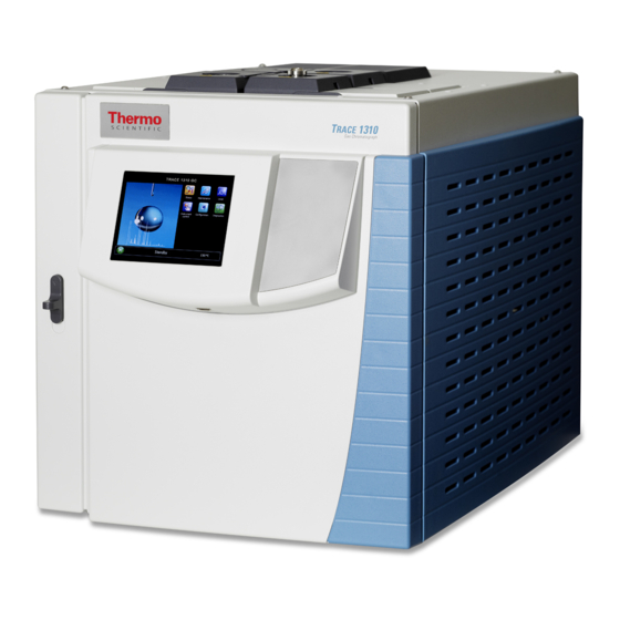
Thermo Scientific TRACE 1300 Installation Manual
Dual detector microfluidics
Hide thumbs
Also See for TRACE 1300:
- Instruction manual (158 pages) ,
- Installation manual (24 pages) ,
- Hardware manual (624 pages)
Summary of Contents for Thermo Scientific TRACE 1300
- Page 1 TRACE 1300 and TRACE 1310 Gas Chromatographs Dual Detector Microfluidics Installation Guide P/N 31709711 Revision A October 2013...
- Page 2 © 2013 Thermo Fisher Scientific Inc. All rights reserved. TSQ 8000, ISQ, TRACE 1300, and TRACE 1310 are trademarks of Thermo Fisher Scientific. SilFlow, and FingerTite are registered trademarks of SGE Analytical Science. All other trademarks are the property of Thermo Fisher Scientific and its subsidiaries.
-
Page 3: Kit Description
Dual Detector Microfluidics Installation Guide This quick-start guide provides instructions for installing the Dual Detector Microfluidics on your TRACE 1300 or TRACE 1310 GC, and your ISQ or TSQ 8000 mass spectrometer. Contents • Kit Description • Connecting the Dual Detector Microfluidics •... - Page 4 The transfer tubings to be used are two 170 μm i.d., 60 cm long tubings. Figure 3 shows the schematic diagram of the kit. Dual Detector Microfluidics Installation Guide Thermo Scientific...
-
Page 5: Connecting The Dual Detector Microfluidics
Connecting the Dual Detector Microfluidics To connect the dual detector microfluidics to the TRACE 1300/1310 GC 1. Cool the oven, injector or injectors, transfer line, ion source, and any installed GC detectors to room temperature and shut down the GC. -
Page 6: Installing The Mounting Bracket
6. Loosely replace the nut, then rotate the top and bottom in opposite directions. 7. Tighten the nut until the mounting bracket is securely attached to the top and bottom of the GC oven. Dual Detector Microfluidics Installation Guide Thermo Scientific... - Page 7 Installing the Mounting Bracket Figure 6. Mounting Bracket Installed in the GC 8. Attach the Thermo Scientific™ microfluidics splitter to the mounting bracket. 9. The microfluidics splitter snaps into place. The small hole should be positioned at the top. See Figure 7 for the correct orientation.
-
Page 8: Preparing The Dual Detector Microfluidics Restrictor Tubing
Then use the SilFlow pre-swage tool to secure the ferrule into position. When done properly, the tubing will extend slightly past the tip of the ferrule. It is important to use the SilFlow pre-swage tool in order to prevent crushing the tip of the fused silica. Dual Detector Microfluidics Installation Guide Thermo Scientific... - Page 9 Figure 12. Swaging the Ferrule Using the SilFlow FingerTite Tool SilFlow FingerTite Pre-Swage Tool 7. Remove the jig, and lay the tubing carefully on the bottom of the GC until you are ready to connect it to the microfluidics splitter. Thermo Scientific Dual Detector Microfluidics Installation Guide...
-
Page 10: Attaching The New Tubing To The Transfer Line
14), which is in the ISQ Toolkit, so that it is even with the lines at the end of the column. Figure 15 indicates proper positioning of the column in the tool for accurate measuring. Dual Detector Microfluidics Installation Guide Thermo Scientific... - Page 11 Figure 16. Positioning the Septum Transfer Line Column Measuring Tool Septum 14. Pull the column back from the transfer line nut. Do not move the septum from its position on the column. Thermo Scientific Dual Detector Microfluidics Installation Guide...
- Page 12 20. Position the column in the transfer line. Use the septum as a guide to measure the correct length you should insert the column. Be careful not to change the location of the septum on the column. Dual Detector Microfluidics Installation Guide Thermo Scientific...
-
Page 13: Attaching The New Tubing To The Gc Detector
You can attach now attach all the capillaries to the microfluidics splitter. To connect the capillaries to the microfluidics splitter 1. Place the ferrule connected to the original GC column into capillary C location on the microfluidics splitter. See Figure Thermo Scientific Dual Detector Microfluidics Installation Guide... - Page 14 4. Close the GC door. 5. Close the vent valve knob. 6. Power on the GC, and set the inlet pressure as indicated in Figure 1 page 7. Power on the mass spectrometer. Dual Detector Microfluidics Installation Guide Thermo Scientific...
-
Page 15: Ordering Parts
SilFlow FingerTite Ferrules 0.4 mm i.d. (10/pk) 29063466 Blanking Ferrule (5/pk) 290ST414 3-Port SilFlow Replacement MCD 60201-398 170 μm Deactivated Tubing 0.363 mm OD 60 cm 60201-390 150 μm Deactivated Tubing 0.363 mm OD 240 cm 0624466TH Thermo Scientific Dual Detector Microfluidics Installation Guide...


Need help?
Do you have a question about the TRACE 1300 and is the answer not in the manual?
Questions and answers