
Related Manuals for Thermo Scientific Lindberg/Blue M Mini-Mite TF55030


Summary of Contents for Thermo Scientific Lindberg/Blue M Mini-Mite TF55030
- Page 1 Thermo Fisher Scientific Lindberg/Blue M Mini-Mite Tube Furnace Models: TF55030, TF55035 Installation and Operating Manual 304243H02 • Revision B • June, 2020...
- Page 2 © 2020 Thermo Fisher Scientific Inc. All rights reserved. Thermo Fisher Scientific Inc. provides this document to its customers with a product purchase to use in the product operation. This document is copyright protected and any reproduction of the whole or any part of this document is strictly prohibited, except with the written authorization of Thermo Fisher Scientific Inc.
-
Page 3: Table Of Contents
Table of Contents Table of Contents Chapter 1 Safety Precautions ............. .1-4 Explanation of Symbols . - Page 4 Table of Contents Thermocouple Replacement ............8-48 Solid-State Relay Replacement .
- Page 5 Figures Figures Figure 1 Mini-mite Tube Furnace ......................2-11 Figure 2 Thermocouple ..........................4-15 Figure 3 Thermocouple Replacement ....................... 8-49 Figure 4 Solid State Relay Replacement ....................8-50 Figure 5 Circuit Breaker Replacement ....................... 8-52 Figure 6 Heating Unit Replacement ......................8-54 Figure 7 Wiring Diagram (TF55030, TF55035) ..................
-
Page 6: Chapter 1 Safety Precautions
Safety Precautions | Chapter 1 Safety Precautions Explanation of Symbols This symbol when used alone indicates important operating instructions which reduce the risk of injury or poor performance of the unit. DANGER : Indicates a hazardous situation which, if not avoided, will result in death or serious injuries. -
Page 7: Safety Considerations
| Safety Precautions Chapter 1 Safety Considerations DANGER : Use this product only in the way described in the product literature and in this manual. Before using it, verify that this product is suitable for its intended use. If the equipment is used in a manner not specified by the manufacturer, the protection provided by the equipment may be impaired. -
Page 8: Standards And Directives
Safety Precautions | Chapter 1 WARNING : This product can expose you to chemicals including arsenic, which is known to the state of California to cause cancer. For more information go to www.P65Warnings.ca.gov. WARNING : Before maintaining this equipment, read the applicable SDS (Safety Data Sheets). -
Page 9: Electromagnetic Compatibility
| Safety Precautions Chapter 1 Electromagnetic Compatibility FCC Statement (USA) Any changes or modifications not expressly approved by the party responsible for compliance could void the user’s authority to operate the equipment. NOTE: This equipment has been tested and found to comply with the limits for a Class A digital device, pursuant to part 15 of the FCC Rules. - Page 10 Safety Precautions | Chapter 1 RoHS - Europe Thermo Fisher Scientific is determined to reduce the impact on the environment and so can declare that this product fully complies with the European Parliament’s RoHS2 (Restriction of Hazardous Substances) Directive 2011/65/EU, with respect to all the following substances: Lead (0.1%) ...
- Page 11 | Safety Precautions Chapter 1 304243H02 Mini-mite Tube Furnace...
-
Page 12: Chapter 2 Introduction
The low thermal mass Moldatherm ® insulation/heating element provides fast duty cycles, energy conservation and efficient programming. Refer to Table 1 “Lindberg/Blue M Mini-Mite TF55030 and TF55035 Series Moldatherm Tube Furnaces” for specifications. Features and Benefits Controlled heat-up rate eliminates thermal shock to materials. -
Page 13: Specifications
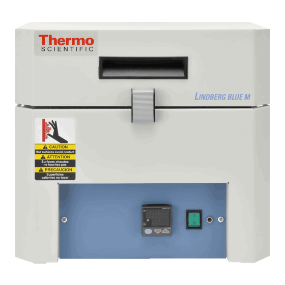
| Introduction Chapter 2 Specifications Figure 1 Mini-mite Tube Furnace Table 1 Lindberg/Blue M Mini-Mite TF55030 and TF55035 Series Moldatherm Tube Furnaces TF55030 C-1** TF55035 C-1** TF55030 A-1* TF55035 A-1* Models TF55030 COMC-1** TF55035 COMC-1** TF55030 COMA-1* TF55035 COMA-1* TF55030 KC-1***... -
Page 14: Chapter 3 Pre-Installation
Operating Conditions High concentrations of sulfates, chlorides, fluorides, alkalis and V 2 O 5 can have corrosive effects on the ceramic fiber. Contact Thermo Scientific for additional information about the effects of specific atmospheres on furnace performance. With prolonged use, hairline cracks can develop in the insulation materials. These minor cracks will not affect the furnace's performance. -
Page 15: Atmosphere Systems
| Pre-Installation Chapter 3 Atmosphere Systems The Lindberg/Blue M Mini-Mite furnaces are designed for use with combustible or inert atmospheres when contained in a process tube. WARNING : Do not use combustible gases directly in this furnace. Process gasses must always be contained in a separate tube. CAUTION : Avoid combustible products which generate toxic or hazardous vapor or fumes. -
Page 16: Chapter 4 Installation
Installation | Chapter 4 Installation CAUTION : Be sure ambient temperature does not exceed 40°C (104°F). Ambient above this level may result in damage to the controller. The recommended ambient temperature is 17°C to 27°C (62.6°F to 80.6°F). CAUTION : Allow at least 12"(30.48 cm) of space between the furnace, at least 12"(30.48 cm) above the furnace and any combustible surface. - Page 17 | Installation Chapter 4 120 VAC Operation The TF55030 A-1 & TF55035 A-1 model operates on 120 VAC, 50/60 Hz, single phase. Each furnace includes a 120 VAC grounded plug and cord set. The units are completely prewired and ready for operation. Before initial start up, inspect the furnace's wiring connections: 1.
- Page 18 Installation | Chapter 4 240 VAC Operation The TF55030C-1, TF55030KC-1, TF55035C-1 and TF5535KC-1 models operate on 240 VAC, 50/60Hz, single phase. The Lindberg/Blue M Moldatherm tube furnace heating elements are specifically designed for operation on 120, 208 or 240 VAC. A furnace wired for 240 VAC operation can also operate on 208 VAC.
- Page 19 | Installation Chapter 4 4-17 Mini-mite Tube Furnace 304243H02...
-
Page 20: Start Up
Start Up | Chapter 5 Start Up WARNING : After transport and decommissioning, or storage under humid conditions a drying-out process must be performed due to hydroscopic nature of the ceramic fiber insulation. During the drying-out process, the equipment cannot be assumed to meet all the safety requirements of the IEC 61010-2-010 standard. - Page 21 | Start Up Chapter 5 5-19 Mini-mite Tube Furnace 304243H02...
-
Page 22: Chapter 6 Main Controller: 1X8 & 5X16 Segment Programmable
Main Controller: 1x8 & 5x16 Segment Programmable | Chapter 6 Main Controller: 1x8 & 5x16 Segment Programmable Eurotherm 3216 Controller The Eurotherm 3216c and 3216p temperature controllers sense the furnace's chamber air temperature (the PV or process value) and provides the heat needed to reach the required set point. -
Page 23: Operator Interface & Home Display
| Main Controller: 1x8 & 5x16 Segment Programmable Chapter 6 Operator Interface & HOME Display When the controller is turned ON, it will perform a brief self-test and then display the HOME Display page. The measured value (process value) is found in the upper display and the set point is found in the lower display. -
Page 24: Operator Buttons
Main Controller: 1x8 & 5x16 Segment Programmable | Chapter 6 Operator Buttons Press to select a new list of parameters and from any display - press PAGE to return to the HOME Page Press to select new parameter from the page header. If held down it will continuously scroll through parameters. -
Page 25: Alternate Set Point Selection (Sp2)
| Main Controller: 1x8 & 5x16 Segment Programmable Chapter 6 Alternate Set Point Selection (SP2) 1. Press the SCROLL button from HOME display until SP.SEL is displayed. 2. Press UP or DOWN button to select SP1 or SP2. If SP2 is selected, then SPX beacon will appear on the HOME display indicating the action of alternate set point in use. -
Page 26: View Or Change The Display Units
Main Controller: 1x8 & 5x16 Segment Programmable | Chapter 6 Complete the following steps to change the ramp rate of SSP. 6. Press the SCROLL button until SP.RAT is displayed. 7. Press UP or DOWN button until the desired ramp rate is indicated on the display. -
Page 27: Auto Tuning
| Main Controller: 1x8 & 5x16 Segment Programmable Chapter 6 d. (NONE): No units displayed e. (PERC): Percent NOTE Do not use nonE & PErc, they are used to measure other applications types other than temperature. Auto Tuning In Auto Tuning the characteristics (PID parameters) of the controller are matched to the characteristics of the product load in order to obtain good control. -
Page 28: Parameter List
Main Controller: 1x8 & 5x16 Segment Programmable | Chapter 6 4. To enable the auto-tune, set the A.TUNE parameter to ON by using DOWN or UP button. 5. Press the PAGE button to return to the HOME display. The display will flash TUNE to indicate that tuning is in progress. - Page 29 | Main Controller: 1x8 & 5x16 Segment Programmable Chapter 6 Operator Level 2 Operator Level 2 provides access to additional parameters and this access is protected by a security code. The Level 2 access should typically be granted to a specially trained person, since changing parameters can have major impact on the temperature performance of the furnace.
-
Page 30: Offset Procedure
Main Controller: 1x8 & 5x16 Segment Programmable | Chapter 6 To Return to Level 1 1. Press and hold PAGE button to show the current operator level. 2. Press UP DOWN button to select LEv 1. When Level 1 is selected the display reverts to the HOME display. A passcode is not required when moving from a higher level to a lower level. -
Page 31: Alarms & Diagnostics
| Main Controller: 1x8 & 5x16 Segment Programmable Chapter 6 To Apply an Offset Connect the input of the controller to the source device which you wish to calibrate to. Set the source to the desired calibration value. The controller will display the current measurement of the value. -
Page 32: Sensor Break & Loop Break Protection
Main Controller: 1x8 & 5x16 Segment Programmable | Chapter 6 Sensor Break & Loop Break Protection Sensor Break Protection - The controller provides sensor break protection in the event the thermocouple opens. If an open thermocouple condition occurs, the digital display will blink “S.br”, a red alarm beacon will be illuminated and the power to the heating element will be shut off. - Page 33 | Main Controller: 1x8 & 5x16 Segment Programmable Chapter 6 Program/Timer Segment Types In program ON condition each segment consists of a controlled ramp rate to a target set point followed by a dwell at that set point. These values can be set by the user. a.
-
Page 34: 1-Program 8-Segment Controller Operation
Main Controller: 1x8 & 5x16 Segment Programmable | Chapter 6 The set point remains constant for a specified period at the specified target. The operating set point of a dwell is inherited from the previous segment. Remaining Time Time remaining before the dwell segment completes. NOTE For all modes except the setpoint programmer, the time remaining may be edited while the program is running, in this case the program duration is modified immediately. - Page 35 | Main Controller: 1x8 & 5x16 Segment Programmable Chapter 6 The 8-segment programmable 3216c controller consists of microprocessor based three-mode PID (Proportional, Integral and Derivative) and appropriate output switching devices to control the furnace. The programmable controller can be used as a single set point controller or as a programmable controller.
-
Page 36: Soft Start Timer
Main Controller: 1x8 & 5x16 Segment Programmable | Chapter 6 Page Parameter Description Level Access Value ADDR** Comms Address Level 2 Read/Write 7-47 BAUD** BAUD RATE Level 2 Read/Write 9600 7-47 IN.TYP Input Type Level 2 Read Only K Type Thermocouple Customer ID Level 2... -
Page 37: Delayed Switch On Timer
| Main Controller: 1x8 & 5x16 Segment Programmable Chapter 6 Soft Start Power Limit The soft start function limits the power delivered to the heater until it has warmed up. The SS.PWR is the power limit applied until the PV reaches the SS.SP or the timer has elapsed. - Page 38 Main Controller: 1x8 & 5x16 Segment Programmable | Chapter 6 Timer Start Threshold A single threshold value is available to provide a holdback on the entry to the dwell part of the ramp/dwell pair. It holds back the dwell until the PV has reached the band defined by +/- threshold around the PV.
- Page 39 | Main Controller: 1x8 & 5x16 Segment Programmable Chapter 6 End Type parameter The action which occurs at the end of program or in reset depends on the configuration of the ‘END.T’ parameter. The ‘END.T’ can be: OFF : The heating is turned OFF, dwEll : Controls at last program setpoint, SP2 : Controls at setpoint 2 (When the timer completes the target setpoint will switch to setpoint 2.
- Page 40 Main Controller: 1x8 & 5x16 Segment Programmable | Chapter 6 3. Now set the threshold by pressing SCROLL button to select ‘THRES’. Press or DOWN button to adjust the value (In this example, the dwell periods will not start until the PV is within 5 units of the set point). 4.
- Page 41 | Main Controller: 1x8 & 5x16 Segment Programmable Chapter 6 To Operate the Programmer Operation Action Indication To Run a program Press and quickly Beacon RUN = On Scrolling display - TIMER RUNNING release To Hold a program Press and quickly Beacon RUN = Flashing Scrolling display - TIMER HOLD release...
-
Page 42: 5-Program 16-Segment Controller Operation
Main Controller: 1x8 & 5x16 Segment Programmable | Chapter 6 AUTO/MAN/OFF: (Auto/Manual/OFF Mode) Operation Action Indication To change Auto to Press and hold Controller display Shows Auto mode Manual model as A-M. for more than 3 seconds 1. AUTO: When the controller is in the automatic mode the output automatically adjusts to keep the temperature or process value at the setpoint. -
Page 43: Figure 2 Thermocouple
| Main Controller: 1x8 & 5x16 Segment Programmable Chapter 6 Table 3 Parameter Description and Accessibility in 3216p Page No. Parameter Description Level Access Value P.STAT Program Status Level 1 + 2 Read/Write Reset 6-31 Timer Remaining T.REMN Level 1 + 2* Read Only* - 6-32 T.ELAP Elapsed Time... - Page 44 Main Controller: 1x8 & 5x16 Segment Programmable | Chapter 6 Holdback Function The temperature ramp rate of the program is quicker than the furnace can achieve. the program will wait until the temperature of the furnace catches up. e.g. If a Holdback value of 10 is set and the program is set to ramp to a set point of 600°C, the program will reach 600°C, then go into an hold state;...
- Page 45 | Main Controller: 1x8 & 5x16 Segment Programmable Chapter 6 3. Press the UP or DOWN button to select a number for a new program or to edit an existing program. The scrolling display shows “CURRENT PROGRAM NUMBER”. End Type parameter The action which occurs at the end of program or in reset depends on the configuration of the ‘END.T’...
- Page 46 Main Controller: 1x8 & 5x16 Segment Programmable | Chapter 6 To Configure the Programmer 1. Enter level 2: refer to section “To Enter Level 2” for steps to enter Level 2. 2. To select the Programmer, press as many times as necessary to view ‘PROG’.
- Page 47 | Main Controller: 1x8 & 5x16 Segment Programmable Chapter 6 8. To set the first Dwell, press SCROLL button to select ‘DWEL.1’. Press DOWN or UP button to set the value. 9. Now repeat the above three steps (6, 7 & 8) to set remaining all segments. NOTE If not all the segments are used for a program, the Ramp &...
-
Page 48: Chapter 7 Communication Option
Communication Option | Chapter 7 Communication Option The factory installed optional RS 485 Digital Communications Port allows controller to be connected to a PC for remote monitoring and control of the furnace. The equipment with communication option (COM) is equipped with two DB9 serial ports (1 Male port & 1 Female port). -
Page 49: Controller Parameters For Communication
| Communication Option Chapter 7 Controller Parameters for Communication Table 4 Controller Parameters for Communication Parameter Value Comms Module Identity Comms (67) Communications Protocol Modbus Communication Interface RS 485 Baud Rate 9600_baud (0) Parity none Comms Address Troubleshooting Communications If your connection is not working properly, check the following conditions: A. -
Page 50: Chapter 8 Maintenance & Cleaning
Maintenance & Cleaning | Chapter 8 Maintenance & Cleaning CAUTION : Maintenance should only be performed by trained personnel. WARNING : Disconnect furnace from main power before attempting any maintenance to furnace or its controls. WARNING : Before maintaining this equipment, read the applicable SDS (Safety Data Sheets). -
Page 51: Figure 3 Thermocouple Replacement
| Maintenance & Cleaning Chapter 8 3. Remove the eight corner screws from the back furnace panel. Locate the thermocouple (in Figure 3). NOTE There are wires connecting the back panel to the furnace. Be careful to place the back panel next to the furnace without disturbing these wires. 4. -
Page 52: Solid-State Relay Replacement
Maintenance & Cleaning | Chapter 8 Solid-State Relay Replacement WARNING : Disconnect furnace from main power before attempting any maintenance to furnace or its controls. If the solid-state relay is inoperable, complete the following steps to replace the relay (refer to Figure 4 “Solid State Relay Replacement”): 1. -
Page 53: Contactor Replacement
| Maintenance & Cleaning Chapter 8 Contactor Replacement WARNING : Disconnect furnace from main power before attempting any maintenance to furnace or its controls. If the contactor is inoperable, complete the following steps to replace the contactor (refer to Figure 4 “Solid State Relay Replacement”): 1. -
Page 54: Circuit Breaker Replacement
Maintenance & Cleaning | Chapter 8 Circuit Breaker Replacement The control circuitry is protected by two circuit breakers located at the rear of the furnace (lower left side). When a circuit breaker opens, a white indicator tab is visible. Check the circuit for faults and press the circuit breaker switch to reset. - Page 55 | Maintenance & Cleaning Chapter 8 4. Remove the nuts and washers holding the twisted wires to the terminal block and remove the wires. Remove the ring lugs from the twisted wires. Save the nuts, washers and ring lugs for reassembly. 5.
-
Page 56: Cleaning And Decontamination
Maintenance & Cleaning | Chapter 8 Figure 6 Heating Unit Replacement Cleaning and Decontamination Furnace must be kept clean in order to ensure proper operation. Cleaning routine should be started with furnace at room temperature. 1. Vacuum the chamber to remove dust/debris, if needed. 2. - Page 57 | Maintenance & Cleaning Chapter 8 8-55 Mini-mite Tube Furnace 304243H02...
-
Page 58: Chapter 9 Troubleshooting
Troubleshooting | Chapter 9 Troubleshooting WARNING : Troubleshooting procedures involve working with high voltages which can cause injury or death. Troubleshooting should only be performed by trained personnel. This section is a guide to troubleshooting furnace problems. Table 5 Eurotherm 3216 Controller Troubleshooting Problem Probable Cause Solution... - Page 59 | Troubleshooting Chapter 9 Table 6 Troubleshooting Problem Solution Furnace temperature Check solid-state relay: runs away. Remove the controller from the furnace. Connect power to the furnace. If the heating unit heats, replace the solid-state relay. Contact your supplier Front panel red indicator light is on: If the controller output light is off, check that the setpoint temperature is higher than the furnace display temperature.
-
Page 60: Chapter 10 Wiring Diagrams
Wiring Diagrams | Chapter 10 Wiring Diagrams Figure 7 Wiring Diagram (TF55030, TF55035) Mini-mite Tube Furnace 304243H02 | 10-58... - Page 61 | Wiring Diagrams Chapter 10 10-59 Mini-mite Tube Furnace 304243H02...
-
Page 62: Chapter 11 Replacement Parts
Replacement Parts | Chapter 11 Replacement Parts Table 7 Model TF55030, Mini-mite Tube Furnaces, 1100°C Description Item TF55030A-1 TF55030COMA-1 TF55030C-1 TF55030COMC-1 TF55030KC-1 Heating unit 301571H01 Thermocouple 7299-1186-00B Assembly Thermocouple 7214-2051-00A Head Single 7299-1122-0BS Thermocouple Temperature CN71X301 Controller CN71X302 Solid-State 102460 Relay Power Cord GT430263... - Page 63 | Replacement Parts Chapter 11 Table 8 Model TF55035, Mini-mite Tube Furnaces, 1100°C Description Item TF55035A-1 TF55035COMA-1 TF55035C-1 TF55035COMC-1 TF55035KC -1 Heating unit 301571H01 Thermocouple 7299-1186-00B Assembly Thermocouple 7214-2051-00A Head Single 7299-1122-0BS Thermocouple Temperature CN71X303 Controller CN71X304 Solid-State 102460 Relay Power Cord GT430263 120 VAC...
-
Page 64: Chapter 12 End Of Life Care
End of Life Care | Chapter 12 End of Life Care Be sure to follow local regulations when disposing of any unit. Some additional suggestions are listed below: Be sure to clean up any biological safety hazards Have a certified technician remove the insulation from the unit then dispose per SDS ... -
Page 65: Weee Compliance
Further information on our compliance with these Directives, the recyclers in your country, and information on Thermo Scientific products which may assist the detection of substances subject to the RoHS Directive are available at www.thermofisher.com/ Deutschland WEEE Konformittät. -
Page 66: Chapter 13 Contact Information
Contact Information | Chapter 13 Contact Information Thermo Fisher Scientific products are backed by a global technical support team ready to support your applications. Visit www.thermofisher.com or call: Countries Sales North America +1 866 984 3766 India toll free 1800 22 8374 India +91 22 6716 2200 China... - Page 67 | Contact Information Chapter 13 13-65 | 304243H02 Mini-mite Tube Furnace...
- Page 68 Find out more at thermofisher.com...