
Related Manuals for Thermo Scientific TRACE GC Ultra


Summary of Contents for Thermo Scientific TRACE GC Ultra
- Page 1 Thermo Scientific NPD Upgrade Kit Per TRACE™ GC Ultra Installation Guide PN 317 093 29, Revision April 2009 Home...
- Page 2 NPD Upgrade Kit for TRACE™ GC - Ultra Installation Guide April 2009 Edition Part Number 317 093 29 © 2007-2009 Thermo Fisher Scientific Inc. All rights reserved. Printed in ITALY. Published by Thermo Fisher Scientific S.p.A. Technical Publications, Strada Rivoltana 20090 Rodano - Milan Tel: +39 02 950591 Fax: +39 02 95059388 Printing History: First Edition, released May 1999 Second Edition, released January 2000...
-
Page 3: Table Of Contents
GC Rear Panel Fixing Screws ......................12 Extension Slots Top View ......................... 13 Detector Control Card Expansion Slots .................... 14 TRACE GC Ultra Right Side View ....................16 TRACE GC Ultra Rear View ......................17 Transformer Installation ........................18 Transformer Assembly Identification Parts ..................19 Installation of the Transformer for NPD ................... - Page 4 Contents Installation of the NPD ........................22 Installation Guide...
-
Page 5: Nitrogen Phosphorus Detector
Nitrogen Phosphorus Detector This guide provides the instructions to install and configure the Nitrogen Phosphorus Detector on your TRACE GC Ultra. Guide at a Glance… About This Guide ....................6 Introduction ......................6 Getting Started......................7 Configuration......................24 Set NPD Parameters .....................26 Operating Sequences Installing NPD Upgrade Kit ...................9... -
Page 6: About This Guide
For Conventions, Symbols and Costumer Communications, please refer to the TRACE GC Ultra Operating Manual. Introduction The upgrade kit contains all the material required to install the Nitrogen Phosphorus Detector on your TRACE GC Ultra: • NPD Assembly for TRACE •... -
Page 7: Transformer For Npd
Gas to Gas 2 Gas 1 Gas 3 For further details, refer to Chapters 16 and Chapter 19 of the TRACE GC Ultra Operating Manual. Transformer for NPD To supply NPD, the dedicated transformer provided must be installed on the Power Control Module of the GC. - Page 8 Upgrade Kit Nitrogen Phosphorus Detector Getting Started • Configure the transformer. • Configure the detector. Before starting, the following preliminary operations must be carried out: 1. Cool the oven and detector base body to room temperature. 2. Make sure that the detector base body is leak free. 3.
-
Page 9: Removing The Gc Panels
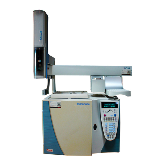
Nitrogen Phosphorus Detector OPERATING SEQUENCE Installing NPD Upgrade Kit Follow this instruction to properly install the NPD Upgrade Kit. Figure 1-1. The TRACE GC Ultra Removing the GC Panels This operation allows to access the GC upper parts and the electronic compartment. -
Page 10: Trace Gc Ultra Top Cover
Open the oven door and unscrew the two top cover fastening screws. 3. Push the cover back about 1 cm and lift it up and off the GC. Figure 1-2. TRACE GC Ultra Top Cover Remove the GC Right Side Panel 1. -
Page 11: Trace Gc Ultra Rear Panel
Getting Started Nitrogen Phosphorus Detector 1. Right Panel Securing Screw Figure 1-3. TRACE GC Ultra Rear Panel Remove the GC Rear Panel 1. Locate the six Allen screws that secure the rear panel to the GC. Remove these screws using the 2-mm Allen wrench. See Figure 1-5. -
Page 12: Gc Rear Panel Fixing Screws
Upgrade Kit Nitrogen Phosphorus Detector Getting Started 1. Rear Panel Fixing Screws Figure 1-4. GC Rear Panel Fixing Screws Installation Guide... -
Page 13: Installing The Npd Control Card
Upgrade Kit Getting Started Nitrogen Phosphorus Detector Installing the NPD Control Card The NPD control card must be installed into the proper expansion slot marked A, B or C located on the left part of the GC mother board in the electronic compartment. -
Page 14: Detector Control Card Expansion Slots
Upgrade Kit Nitrogen Phosphorus Detector Getting Started 1. Detector control card expansion Slots 2. Additional heat control jumpers 3. Mother board Figure 1-6. Detector Control Card Expansion Slots 2. Verify that the jumper marked Jx, adjacent to the defined detector control card connector on the mother board, is positioned between the pins 2 and 3. - Page 15 Upgrade Kit Getting Started Nitrogen Phosphorus Detector Jumper Positioning Pins 1-2 = additional heat control enabled Pins 2-3 = additional heat control not enabled WARNING! The jumper marked “Jx” must be positioned between the pins 2 and 3. 3. Guide through the slot mentioned at point 1 the signal and ignition cables coming from the top of the card.
-
Page 16: Removing The Power Control Module
1. Remove the six screws. Refer to Figure 1-7. 1. Large Phillips Screws Figure 1-7. TRACE GC Ultra Right Side View 2. Slide the Power Control Module very slowly and gently outward towards the rear of the GC. See Figure 1-8 on page 17. -
Page 17: Trace Gc Ultra Rear View
Getting Started Nitrogen Phosphorus Detector 1. Power Control Module Figure 1-8. TRACE GC Ultra Rear View 3. As the Power Control Module is being removed, disconnection of the parts must be carried out in the following order: • J1, 16-pin white connector. -
Page 18: Install The Transformer For Detector
Upgrade Kit Nitrogen Phosphorus Detector Getting Started Install the Transformer for Detector Figure 1-9 shows the positions on the GC Power Control Module where the detector trasformer must be installed. 1. Installation Position of the Transformer for NPD Figure 1-9. Transformer Installation Install the transformer proceeding as follows. -
Page 19: Transformer Assembly Identification Parts
Upgrade Kit Getting Started Nitrogen Phosphorus Detector 7. Screw until the transformer assembly is blocked. 1. Transformer 2. Protection disks 3. Spacer 4. Metal Plate 5. Fixing Screw Figure 1-10. Transformer Assembly Identification Parts The transformer has three cables and four female connectors marked “Px”. Connect the female connectors to the corresponding male connectors marked “Jx”on the power control module PCB (J14, J15) and on the mother board PCB (J35, J36, J37) depending where the NPD board has been installed. -
Page 20: Reinstall The Power Control Module
Upgrade Kit Nitrogen Phosphorus Detector Getting Started Figure 1-11. Installation of the Transformer for NPD Reinstall the Power Control Module CAUTION This operation requires particular attention because several cables must be reconnected to the Power Control Module. It must be gradually reinserted paying attention to reconnect step by step all the cables until the power control module is completely reinstalled into the GC. -
Page 21: Mounting The Npd On The Gc
Upgrade Kit Getting Started Nitrogen Phosphorus Detector Mounting the NPD on the GC This operation allows the correct installation of the NPD on your TRACE GC Ultra. Material needed • Jet for NPD • Tool for jet 1. Place the jet into the detector base body housing and tighten it with the proper tool. -
Page 22: Reinstall The Gc Panels
Upgrade Kit Nitrogen Phosphorus Detector Getting Started 1. NPD 2. Fixing screw 3. Detector base body 4. Signal cable 5. Ignition polarization cable Figure 1-13. Installation of the NPD Reinstall the GC Panels This operation allows to reinstall the GC panels Material needed: •... -
Page 23: Restarting The Gc
Upgrade Kit Getting Started Nitrogen Phosphorus Detector Restarting the GC 1. Verify that the connections of the detector gases has been correctly performed. 2. Open the gas supplies. 3. Reconnect the main power. 4. Turn on main power. Installation Guide... -
Page 24: Configuration
Detector and Make-up Gas Configuration You configure the detector and make-up gas in the menu. Refer to CONFIGURE Chapter 15 of the TRACE GC Ultra Operating manual. 1. Press CONFIG then scroll to Left detector Right detector depending on the location of the detector to configure. Press ENTER to open the detector gas menu. - Page 25 Upgrade Kit Configuration Nitrogen Phosphorus Detector LEFT DETECTOR Detector type < Makeup gas 1 This line appears only if the DGFC module is present. Refer to note. 2. Select . This line indicates the type of detector mounted and Detector type the slot (A, B or C) of the relevant control board.
-
Page 26: Set Npd Parameters
To set NPD parameters, it is necessary to open the NPD menu and the NPD Signal menu. • menu contains the detector control parameters. DETECTOR (NPD) To set parameters, refer to the Chapter 19 of the TRACE GC Ultra Operating Manual. • menu contains the parameters that control the DETECTOR SIGNAL detector signal. - Page 27 Upgrade Kit Set NPD Parameters Nitrogen Phosphorus Detector 1. These settings could also be for a right detector. 2. If you have a non-DGFC module, the actual value are not displayed, and you can only turn the flows on and off. 2.
- Page 28 Upgrade Kit Nitrogen Phosphorus Detector Set NPD Parameters Installation Guide...
Need help?
Do you have a question about the TRACE GC Ultra and is the answer not in the manual?
Questions and answers