
Related Manuals for ITT 3610 i-FRAME


Summary of Contents for ITT 3610 i-FRAME
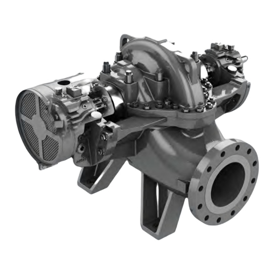
- Page 1 3610 i-FRAME API 610 11th Ed/ISO 13709 2nd Ed, API Type BB1 Single-Stage, Axially-Split, Between-Bearing...
-
Page 3: Table Of Contents
4.4.10 Perform complete alignment for a horizontal correction.............. 30 4.5 Grout the baseplate..........................30 4.6 Piping checklists............................32 4.6.1 General piping checklist ........................ 32 3610 i-FRAME API 610 11th Ed/ISO 13709 2nd Ed, API Type BB1 Single-Stage, Axially-Split, Between-Bearing IOM... - Page 4 6.4.1 Disassembly precautions ......................68 6.4.2 Tools required..........................68 6.4.3 Prepare for disassembly ....................... 69 6.4.4 Disassemble the radial end (ball bearing pumps) ................. 70 3610 i-FRAME API 610 11th Ed/ISO 13709 2nd Ed, API Type BB1 Single-Stage, Axially-Split, Between-Bearing IOM...
- Page 5 8.2 Cross-sectional diagrams........................123 9 Other Relevant Documentation or Manuals....................126 9.1 For additional documentation ........................ 126 10 Local ITT Contacts ............................127 10.1 Regional offices........................... 127 3610 i-FRAME API 610 11th Ed/ISO 13709 2nd Ed, API Type BB1 Single-Stage, Axially-Split, Between-Bearing IOM...
-
Page 6: Introduction And Safety
ITT. If there is any uncertainty regarding the appropriate use of the equipment, please contact an ITT representative before proceeding. 3610 i-FRAME API 610 11th Ed/ISO 13709 2nd Ed, API Type BB1 Single-Stage, Axially-Split, Between-Bearing IOM... -
Page 7: Safety Terminology And Symbols
Hazard categories can either fall under hazard levels or let specific symbols replace the ordinary hazard level symbols. Electrical hazards are indicated by the following specific symbol: 3610 i-FRAME API 610 11th Ed/ISO 13709 2nd Ed, API Type BB1 Single-Stage, Axially-Split, Between-Bearing IOM... -
Page 8: Environmental Safety
For electrical installation recycling requirements, consult your local electric utility. 1.2.2.1 Recycling guidelines Always follow local laws and regulations regarding recycling. 1.2.3 User safety General safety rules These safety rules apply: 3610 i-FRAME API 610 11th Ed/ISO 13709 2nd Ed, API Type BB1 Single-Stage, Axially-Split, Between-Bearing IOM... - Page 9 Read this manual carefully before instal- ling and using the product. • Never work alone. • Always wear protective clothing and hand protection. • Stay clear of suspended loads. 3610 i-FRAME API 610 11th Ed/ISO 13709 2nd Ed, API Type BB1 Single-Stage, Axially-Split, Between-Bearing IOM...
-
Page 10: Ex-Approved Products
Any maintenance for Ex-approved products must conform to international and national standards (for example, IEC/EN 60079-17). ITT disclaims all responsibility for work done by untrained and unauthorized personnel. 3610 i-FRAME API 610 11th Ed/ISO 13709 2nd Ed, API Type BB1 Single-Stage, Axially-Split, Between-Bearing IOM... -
Page 11: Monitoring Equipment
Compliance is fulfilled only when you operate the unit within its intended use. Do not change the condi- tions of the service without the approval of an ITT representative. When you install or maintain explosion proof products, always comply with the directive and applicable standards (for example, IEC/EN 60079–... -
Page 12: Product Warranty
ITT products are high-quality products with expected reliable operation and long life. However, should the need arise for a warranty claim, then contact your ITT representative. 3610 i-FRAME API 610 11th Ed/ISO 13709 2nd Ed, API Type BB1 Single-Stage, Axially-Split, Between-Bearing IOM... -
Page 13: Transportation And Storage
Risk of serious personal injury or equipment damage. Proper lifting practices are critical to safe transport of heavy equipment. Ensure that practices used are in compliance with all applicable regulations and standards. 3610 i-FRAME API 610 11th Ed/ISO 13709 2nd Ed, API Type BB1 Single-Stage, Axially-Split, Between-Bearing IOM... - Page 14 Hoist a bare pump using suitable slings under the bearing housing saddle on each end. Figure 1: Example of the proper lifting method for a bare pump Baseplate-mounted units have lifting points for use with proper lifting devices. 3610 i-FRAME API 610 11th Ed/ISO 13709 2nd Ed, API Type BB1 Single-Stage, Axially-Split, Between-Bearing IOM...
-
Page 15: Storage Guidelines
Treat bearing and machined surfaces so that they are well preserved. Refer to the drive unit and cou- pling manufacturers for their long-term storage procedures. 3610 i-FRAME API 610 11th Ed/ISO 13709 2nd Ed, API Type BB1 Single-Stage, Axially-Split, Between-Bearing IOM... - Page 16 2.3 Storage guidelines For questions about possible long-term storage treatment services, please contact your local ITT sales representative. 3610 i-FRAME API 610 11th Ed/ISO 13709 2nd Ed, API Type BB1 Single-Stage, Axially-Split, Between-Bearing IOM...
-
Page 17: Product Description
3 Product Description 3 Product Description 3.1 General description Product description The Model 3610 i-FRAME is a horizontal centrifugal pump that meets the latest editions of API 610 and ISO 13709 and has these characteristics: • Safety, Reliability, and Versatility •... -
Page 18: General Description I-Alert®2 Equipment Condition Monitor
Item numbers can be found in the spare parts list. Refer to the nameplate on the pump casing for most of the information. See Parts List for item numbers. 3610 i-FRAME API 610 11th Ed/ISO 13709 2nd Ed, API Type BB1 Single-Stage, Axially-Split, Between-Bearing IOM... - Page 19 Customer contract or item number IMP. DIA. Rated impeller diameter, inches MAX. DIA. Maximum impeller diameter, inches STD. DIM. Standard ANSI dimensional code MAT'L Material of construction 3610 i-FRAME API 610 11th Ed/ISO 13709 2nd Ed, API Type BB1 Single-Stage, Axially-Split, Between-Bearing IOM...
- Page 20 Use of equipment unsuitable for the environment can pose risks of ignition and/or explosion. Ensure the pump driver and all other auxiliary components meet the required area classifica- tion at the site. If they are not compatible, do not operate the equipment and contact an ITT representative before proceeding.
-
Page 21: Installation
If the pump location is overhead, undertake special Consider a consultation with a noise specialist. precautions to reduce possible noise transmission. 3610 i-FRAME API 610 11th Ed/ISO 13709 2nd Ed, API Type BB1 Single-Stage, Axially-Split, Between-Bearing IOM... -
Page 22: Foundation Requirements
Provide a flat, substantial concrete foundation in order to prevent strain and distortion when you tighten the foundation bolts. Sleeve-type bolts Item Description Baseplate Foundation Sleeve Bolt Figure 7: Sleeve type bolts 3610 i-FRAME API 610 11th Ed/ISO 13709 2nd Ed, API Type BB1 Single-Stage, Axially-Split, Between-Bearing IOM... -
Page 23: Baseplate-Mounting Procedures
Make sure that all machined surfaces are free from burrs, rust, paint, or any other type of contami- nation. If necessary, use a honing stone to remove burrs. 3610 i-FRAME API 610 11th Ed/ISO 13709 2nd Ed, API Type BB1 Single-Stage, Axially-Split, Between-Bearing IOM... -
Page 24: Prepare The Foundation For Mounting
4.2.3 Install and level the baseplate NOTICE: Illustrations are for reference only and may not depict the particular pump model. Jackscrews Figure 9: Jackscrew locations, side view 3610 i-FRAME API 610 11th Ed/ISO 13709 2nd Ed, API Type BB1 Single-Stage, Axially-Split, Between-Bearing IOM... -
Page 25: Install The Pump, Driver, And Coupling
Mount and fasten the pump on the baseplate. Use applicable bolts. Mount the driver on the baseplate. Use applicable bolts and hand tighten. Install the coupling. See the installation instructions from the coupling manufacturer. 3610 i-FRAME API 610 11th Ed/ISO 13709 2nd Ed, API Type BB1 Single-Stage, Axially-Split, Between-Bearing IOM... -
Page 26: Pump-To-Driver Alignment
Final alignment (hot alignment) checks When After the first run This ensures correct alignment when both the pump and the driver are at op- erating temperature. 3610 i-FRAME API 610 11th Ed/ISO 13709 2nd Ed, API Type BB1 Single-Stage, Axially-Split, Between-Bearing IOM... -
Page 27: Permitted Indicator Values For Alignment Checks
Attach the other indicator (A) so that the indicator rod comes into contact with the inner end of the driver coupling half. This indicator is used to measure angular misalignment. 3610 i-FRAME API 610 11th Ed/ISO 13709 2nd Ed, API Type BB1 Single-Stage, Axially-Split, Between-Bearing IOM... -
Page 28: Perform Angular Alignment For A Vertical Correction
Remove shims in order to lower the feet of the driver at the shaft end. • Add shims in order to raise the feet of the driver at the other end. 3610 i-FRAME API 610 11th Ed/ISO 13709 2nd Ed, API Type BB1 Single-Stage, Axially-Split, Between-Bearing IOM... -
Page 29: Perform Angular Alignment For A Horizontal Correction
Perform one of these steps: • Slide the shaft end of the driver to the right. • Slide the opposite end to the left. 3610 i-FRAME API 610 11th Ed/ISO 13709 2nd Ed, API Type BB1 Single-Stage, Axially-Split, Between-Bearing IOM... -
Page 30: Perform Parallel Alignment For A Vertical Correction
Item Description Shims Figure 14: Example of incorrect vertical alignment (side view) 3610 i-FRAME API 610 11th Ed/ISO 13709 2nd Ed, API Type BB1 Single-Stage, Axially-Split, Between-Bearing IOM... -
Page 31: Perform Parallel Alignment For A Horizontal Correction
A unit is in complete alignment when both the angular indicator (A) and the parallel indicator (P) do not vary by more than 0.05 mm | 0.002 in. as measured at four points 90° apart. 3610 i-FRAME API 610 11th Ed/ISO 13709 2nd Ed, API Type BB1 Single-Stage, Axially-Split, Between-Bearing IOM... -
Page 32: Perform Complete Alignment For A Horizontal Correction
When you pour the grout, remove air bubbles from it by using one of these methods: • Puddle with a vibrator. • Pump the grout into place. Allow the grout to set. 3610 i-FRAME API 610 11th Ed/ISO 13709 2nd Ed, API Type BB1 Single-Stage, Axially-Split, Between-Bearing IOM... - Page 33 Grout Figure 17: Fill remainder of baseplate with grout Remove the leveling jackscrews after the grout hardens in order to remove any stress points. 3610 i-FRAME API 610 11th Ed/ISO 13709 2nd Ed, API Type BB1 Single-Stage, Axially-Split, Between-Bearing IOM...
-
Page 34: Piping Checklists
Guidelines for piping are given in the Hydraulic Institute Standards available from the Hydraulic Institute at 9 Sylvan Way, Parsippany, NJ 07054-3802. You must review this document before you install the pump. 3610 i-FRAME API 610 11th Ed/ISO 13709 2nd Ed, API Type BB1 Single-Stage, Axially-Split, Between-Bearing IOM... - Page 35 4.6.4 Flange face separation shall be within the gasket spacing ±1.5 mm | 1/16 in. Only one gasket per flanged connection shall be used. 3610 i-FRAME API 610 11th Ed/ISO 13709 2nd Ed, API Type BB1 Single-Stage, Axially-Split, Between-Bearing IOM...
-
Page 36: Suction-Piping Checklist
Check that the eccentric reducer at the suction flange of the pump has the follow- ing properties: • Sloping side down • Horizontal side at the top 3610 i-FRAME API 610 11th Ed/ISO 13709 2nd Ed, API Type BB1 Single-Stage, Axially-Split, Between-Bearing IOM... - Page 37 Use a foot valve with a diameter that is at least equiva- device for priming the pump is installed. lent to the diameter of the suction piping. 3610 i-FRAME API 610 11th Ed/ISO 13709 2nd Ed, API Type BB1 Single-Stage, Axially-Split, Between-Bearing IOM...
-
Page 38: Discharge Piping Checklist
You can size and install a minimum-flow orifice in a bypass line in order to prevent bypassing excessive flows. Consult your ITT representative for assistance in sizing a minimum-flow orifice. 3610 i-FRAME API 610 11th Ed/ISO 13709 2nd Ed, API Type BB1 Single-Stage, Axially-Split, Between-Bearing IOM... -
Page 39: Auxiliary-Piping Checklist
Re-check the alignment to make sure that If pipe strain exists, then correct the piping. pipe strain has not caused any misalign- ment. 3610 i-FRAME API 610 11th Ed/ISO 13709 2nd Ed, API Type BB1 Single-Stage, Axially-Split, Between-Bearing IOM... -
Page 40: Commissioning, Startup, Operation, And Shutdown
This prevents seal or shaft sleeve damage by ensuring that the seal is properly installed and centered on the sleeve. 3610 i-FRAME API 610 11th Ed/ISO 13709 2nd Ed, API Type BB1 Single-Stage, Axially-Split, Between-Bearing IOM... -
Page 41: Remove The Coupling Guard
Remove the pump half of the coupling guard: 3610 i-FRAME API 610 11th Ed/ISO 13709 2nd Ed, API Type BB1 Single-Stage, Axially-Split, Between-Bearing IOM... -
Page 42: Check The Rotation
If specific directions are not indicated in the motor instruc- tions, then follow this procedure: NOTICE: If the driver was mounted at the factory, the setting for the coupling is already determined. 3610 i-FRAME API 610 11th Ed/ISO 13709 2nd Ed, API Type BB1 Single-Stage, Axially-Split, Between-Bearing IOM... -
Page 43: Coupling Guard Assembly
Always disconnect and lock out power to the driver before performing any installa- tion or maintenance tasks. • Electrical connections must be made by certified electricians in compliance with all international, national, state, and local rules. 3610 i-FRAME API 610 11th Ed/ISO 13709 2nd Ed, API Type BB1 Single-Stage, Axially-Split, Between-Bearing IOM... - Page 44 If the coupling hub diameter is larger than the diameter of the opening in the end plate, then remove the coupling hub. Remove the thrust bearing end-cover screws. 3610 i-FRAME API 610 11th Ed/ISO 13709 2nd Ed, API Type BB1 Single-Stage, Axially-Split, Between-Bearing IOM...
- Page 45 Place one washer (534A) over the bolt (569E) and insert the bolt through the round hole at the front end of the guard half. 3610 i-FRAME API 610 11th Ed/ISO 13709 2nd Ed, API Type BB1 Single-Stage, Axially-Split, Between-Bearing IOM...
- Page 46 Place the end plate over the driver shaft and locate the end plate in the annular groove at the rear of the coupling guard half. 3610 i-FRAME API 610 11th Ed/ISO 13709 2nd Ed, API Type BB1 Single-Stage, Axially-Split, Between-Bearing IOM...
- Page 47 Figure 24: Slide to fit 10. Repeat Steps 3. through 5. for the center slots in the coupling guard. Firmly tighten all bolts (569E) on the guard assembly. 3610 i-FRAME API 610 11th Ed/ISO 13709 2nd Ed, API Type BB1 Single-Stage, Axially-Split, Between-Bearing IOM...
-
Page 48: Bearing Lubrication
6320 3401 7320/BECBM 3401 6224 3401 7320/BECBM 3401 Oil volume requirements for sleeve/ball This table shows the required amount of oil for oil-lubricated bearings. 3610 i-FRAME API 610 11th Ed/ISO 13709 2nd Ed, API Type BB1 Single-Stage, Axially-Split, Between-Bearing IOM... -
Page 49: Lubricating-Oil Requirements
Remove the oil filter (550A) and the oil filter plug (113Q) from the bearing frame (134). See Figure 25: Oil filter and plug removal on page 3610 i-FRAME API 610 11th Ed/ISO 13709 2nd Ed, API Type BB1 Single-Stage, Axially-Split, Between-Bearing IOM... - Page 50 See Figure 27: Filter kit on page 3610 i-FRAME API 610 11th Ed/ISO 13709 2nd Ed, API Type BB1 Single-Stage, Axially-Split, Between-Bearing IOM...
-
Page 51: Lubricate The Bearings With Oil
Ring oil-lubricated pumps are supplied with an oiler that maintains a constant oil level in the bearing housing. 3610 i-FRAME API 610 11th Ed/ISO 13709 2nd Ed, API Type BB1 Single-Stage, Axially-Split, Between-Bearing IOM... -
Page 52: Convert To Oil-Mist Lubrication
The radialDrive End and Non Drive End bearing housings (134) have pre-drilled connections for oil mist: • 1/4 in. NPT connection on the inboard side of each housing (133H) 3610 i-FRAME API 610 11th Ed/ISO 13709 2nd Ed, API Type BB1 Single-Stage, Axially-Split, Between-Bearing IOM... -
Page 53: Thrust Bearing Cooling Fan (Optional)
Electrical connections must be made by certified electricians in compliance with all international, national, state, and local rules. • Refer to driver/coupling/gear manufacturer's installation and operation manuals (IOM) for specific instructions and recommendations. 3610 i-FRAME API 610 11th Ed/ISO 13709 2nd Ed, API Type BB1 Single-Stage, Axially-Split, Between-Bearing IOM... -
Page 54: Lubricate The Bearings With Pure Or Purge-Oil Mist (Optional)
Oil mist is recommended for use on ball bearing arrangements only. See convert to oil mist lu- brication. Prepare the oil-mist generator according to the manufacturer's instructions. 3610 i-FRAME API 610 11th Ed/ISO 13709 2nd Ed, API Type BB1 Single-Stage, Axially-Split, Between-Bearing IOM... -
Page 55: Lubricate The Bearings With Pressurized Lubrication
32: Oil feed location on page Connect the bearing housing drain piping back to the lubrication oil skid as shown in Figure 33: Oil drain locations on page 3610 i-FRAME API 610 11th Ed/ISO 13709 2nd Ed, API Type BB1 Single-Stage, Axially-Split, Between-Bearing IOM... -
Page 56: Lubricate The Bearings After A Shutdown Period
Flush the bearing housing with the proper lubricating oil to ensure oil quality after cleaning. Refer to Reassembly section for proper bearing greasing procedure. 3610 i-FRAME API 610 11th Ed/ISO 13709 2nd Ed, API Type BB1 Single-Stage, Axially-Split, Between-Bearing IOM... -
Page 57: Shaft Sealing With A Mechanical Seal
Cartridge seals installed by the user require disengagement of the hold- ing clips prior to operation, allowing the seal to slide into place. If the seal has been installed in the pump by ITT, these clips have already been disengaged. Other mechanical seal types For other types of mechanical seals, refer to the instructions provided by the seal manufacturer for instal- lation and setting. -
Page 58: Pump Priming
Close the air vent valves, start the pump, and open the discharge gate valve. The pump will continue to be primed for any future starting. 3610 i-FRAME API 610 11th Ed/ISO 13709 2nd Ed, API Type BB1 Single-Stage, Axially-Split, Between-Bearing IOM... -
Page 59: Prime The Pump With An Outside Supply
During long idle periods, the pump can also lose its prime through leakage from the stuffing boxes. 3610 i-FRAME API 610 11th Ed/ISO 13709 2nd Ed, API Type BB1 Single-Stage, Axially-Split, Between-Bearing IOM... -
Page 60: Prime The Pump By Bypassing The Discharge Check Valve
The valve in the bypass line can be left open so that loss through the foot valve is constantly replen- ished from the discharge line left open during idle periods. 3610 i-FRAME API 610 11th Ed/ISO 13709 2nd Ed, API Type BB1 Single-Stage, Axially-Split, Between-Bearing IOM... -
Page 61: Prime The Pump With An Ejector
Open the discharge gate valve. Valve S Ejector Valve E Steam, compressed air, or water under pressure Discharge gate valve Figure 38: Priming the pump with an ejector 3610 i-FRAME API 610 11th Ed/ISO 13709 2nd Ed, API Type BB1 Single-Stage, Axially-Split, Between-Bearing IOM... -
Page 62: Prime With An Automatic Primer Pump
Reinstall the plugs after confirming. Before you start the pump, you must perform these tasks: 3610 i-FRAME API 610 11th Ed/ISO 13709 2nd Ed, API Type BB1 Single-Stage, Axially-Split, Between-Bearing IOM... -
Page 63: I-Alert®2 Equipment Health Monitor
Risk of equipment damage from unexpected heat generation. Do not overload the driver. Ensure that the pump operating conditions are suitable for the driver. The driver can over- load in these circumstances: 3610 i-FRAME API 610 11th Ed/ISO 13709 2nd Ed, API Type BB1 Single-Stage, Axially-Split, Between-Bearing IOM... - Page 64 Note that different liquids freeze at different temperatures. Some pump designs do not drain completely and may require flushing with a liquid that doesn't freeze. 3610 i-FRAME API 610 11th Ed/ISO 13709 2nd Ed, API Type BB1 Single-Stage, Axially-Split, Between-Bearing IOM...
-
Page 65: Shut Down The Pump
Run the unit under actual operating conditions for enough time to bring the pump, driver, and asso- ciated system to operating temperature. Shut down the pump and the driver. 3610 i-FRAME API 610 11th Ed/ISO 13709 2nd Ed, API Type BB1 Single-Stage, Axially-Split, Between-Bearing IOM... -
Page 66: Doweling The Pump Casing
12. Remove the coupling guard. Refer to . 13. Check and confirm the alignment while the unit is still hot. 3610 i-FRAME API 610 11th Ed/ISO 13709 2nd Ed, API Type BB1 Single-Stage, Axially-Split, Between-Bearing IOM... - Page 67 5.21 Doweling the pump casing 14. Dowel the driver feet. See the driver IOM for details. 3610 i-FRAME API 610 11th Ed/ISO 13709 2nd Ed, API Type BB1 Single-Stage, Axially-Split, Between-Bearing IOM...
-
Page 68: Maintenance
Annual inspections Perform these inspections one time each year: • Check the pump capacity. • Check the pump pressure. • Check the pump power. 3610 i-FRAME API 610 11th Ed/ISO 13709 2nd Ed, API Type BB1 Single-Stage, Axially-Split, Between-Bearing IOM... -
Page 69: Bearing Maintenance
The manufacturer supplies a reference drawing with the data package. Keep this drawing for future use when you perform maintenance and seal adjustments. The seal drawing specifies the required flush fluid and attachment points. 3610 i-FRAME API 610 11th Ed/ISO 13709 2nd Ed, API Type BB1 Single-Stage, Axially-Split, Between-Bearing IOM... -
Page 70: Disassembly
6.4.2 Tools required In order to disassemble the pump, you need these tools: • Brass drift punch • Cleaning agents and solvents • Dial indicators 3610 i-FRAME API 610 11th Ed/ISO 13709 2nd Ed, API Type BB1 Single-Stage, Axially-Split, Between-Bearing IOM... -
Page 71: Prepare For Disassembly
Remove the oil drain plugs (408A) from the bottom of the bearing housings (134, 134A) and drain the oil. Dispose of the oil in accordance with applicable regulations. 501B 234A 234B 235B 408A 408A Figure 40: Coupling guard disassembly 3610 i-FRAME API 610 11th Ed/ISO 13709 2nd Ed, API Type BB1 Single-Stage, Axially-Split, Between-Bearing IOM... -
Page 72: Disassemble The Radial End (Ball Bearing Pumps)
(Optional) Remove the studs (371T). It may be necessary to rotate the bearing housing in order to remove the inboard end cover bolts (371D). Remove the oil ring (114). 3610 i-FRAME API 610 11th Ed/ISO 13709 2nd Ed, API Type BB1 Single-Stage, Axially-Split, Between-Bearing IOM... -
Page 73: Disassemble The Thrust End (Ball Bearing Pumps)
Remove the oil ring sleeve (443B), which is held in place by the thrust locknut (136). 12. Use a bearing puller in order to remove the thrust bearing (112A) from the shaft (122). 3610 i-FRAME API 610 11th Ed/ISO 13709 2nd Ed, API Type BB1 Single-Stage, Axially-Split, Between-Bearing IOM... -
Page 74: Disassemble The Radial End (Sleeve/Ball Bearing Pumps)
Refer to the instructions provided by the mechanical seal manufacturer. 6.4.6 Disassemble the radial end (sleeve/ball bearing pumps) 113Q 550A Item Description Taper pin Jack bolt Figure 45: Disassemble the radial end 3610 i-FRAME API 610 11th Ed/ISO 13709 2nd Ed, API Type BB1 Single-Stage, Axially-Split, Between-Bearing IOM... - Page 75 Remove the lower half of the bearing housing. 12. (Optional) Remove the studs (371T). 13. Remove the outboard labyrinth seal (332A) and the inboard labyrinth seal (333A) and oil ring (114). 3610 i-FRAME API 610 11th Ed/ISO 13709 2nd Ed, API Type BB1 Single-Stage, Axially-Split, Between-Bearing IOM...
-
Page 76: Disassemble The Thrust End (Sleeve/Ball Bearing Pumps)
Move the oil ring (114) aside, it cannot be removed until the lower bearing housing is removed. Remove the upper half of the sleeve bearing (117). 3610 i-FRAME API 610 11th Ed/ISO 13709 2nd Ed, API Type BB1 Single-Stage, Axially-Split, Between-Bearing IOM... - Page 77 Remove the thrust locknut (136) and the lockwasher (382) from the shaft. 16. Remove the oil ring sleeve (443B). 17. Remove bearing retainer (361A). 3610 i-FRAME API 610 11th Ed/ISO 13709 2nd Ed, API Type BB1 Single-Stage, Axially-Split, Between-Bearing IOM...
- Page 78 Never apply heat at the pump site for this reason. Heat can also distort machined surfaces. 19. If applicable - Remove bearing spacer (443V). 20. Remove the inboard labyrinth seals (333A) and oil ring (114). 3610 i-FRAME API 610 11th Ed/ISO 13709 2nd Ed, API Type BB1 Single-Stage, Axially-Split, Between-Bearing IOM...
-
Page 79: Disassemble The Radial End (Sleeve/Tilt Pumps)
Tighten the two jack bolts on the horizontal parting flanges of the bearing housing (134) in order to separate the two halves. Remove the top half of the bearing housing (134). 3610 i-FRAME API 610 11th Ed/ISO 13709 2nd Ed, API Type BB1 Single-Stage, Axially-Split, Between-Bearing IOM... - Page 80 10. Remove the dowel pins (469J) that hold the lower half of the bearing housing to the casing flange. Figure 55: Radial dowel pin removal Loosen and remove the nuts (427J) that hold the bearing housing (134) in place. 3610 i-FRAME API 610 11th Ed/ISO 13709 2nd Ed, API Type BB1 Single-Stage, Axially-Split, Between-Bearing IOM...
-
Page 81: Disassemble The Thrust End (Sleeve/Tilt Pumps)
(219). If the pump was not supplied with a main oil shaft pump (219), go to step 4. Remove the hex cap screws (370N) to remove the oil pump adapter (318A). 3610 i-FRAME API 610 11th Ed/ISO 13709 2nd Ed, API Type BB1 Single-Stage, Axially-Split, Between-Bearing IOM... - Page 82 (134A). 23. Remove the dowel pins (469J) that hold the lower half of the bearing housing to the casing flange. 3610 i-FRAME API 610 11th Ed/ISO 13709 2nd Ed, API Type BB1 Single-Stage, Axially-Split, Between-Bearing IOM...
-
Page 83: Guidelines For I-Alert®2 Equipment Health Monitor Disposal
This product contains Lithium Thionyl Chloride. Contact your local waste management companies to pro- vide assistance in the disposal of the device that contain this type of battery. 3610 i-FRAME API 610 11th Ed/ISO 13709 2nd Ed, API Type BB1 Single-Stage, Axially-Split, Between-Bearing IOM... -
Page 84: Disassemble The Rotating Assembly
Cast lifting lugs in upper half are intended for upper half removal from the pump. They are not intended to be used to lift the entire pump. 3610 i-FRAME API 610 11th Ed/ISO 13709 2nd Ed, API Type BB1 Single-Stage, Axially-Split, Between-Bearing IOM... - Page 85 This value is required for the correct positioning of the impeller in the casing at reassembly. The X dimension is pre-set at the factory. Refer to the Impeller setting table. 3610 i-FRAME API 610 11th Ed/ISO 13709 2nd Ed, API Type BB1 Single-Stage, Axially-Split, Between-Bearing IOM...
-
Page 86: Preassembly Inspections
Inspect the casing and head for cracks and excessive wear or pitting. Thoroughly clean gasket surfaces and alignment fits to remove rust and debris. Repair or replace these parts if you notice any of these conditions: 3610 i-FRAME API 610 11th Ed/ISO 13709 2nd Ed, API Type BB1 Single-Stage, Axially-Split, Between-Bearing IOM... - Page 87 You must have extremely accurate tooling equipment to balance impellers to ISO 1940-1, grade G2.5. Do not attempt to balance impellers to this criteria unless this type of tooling and equipment is available. 3610 i-FRAME API 610 11th Ed/ISO 13709 2nd Ed, API Type BB1 Single-Stage, Axially-Split, Between-Bearing IOM...
- Page 88 Locknut surfaces must be smooth and free of grooves and scratches, especially in the areas indicated by arrows in the figure. Also check the outside diameter of the locknuts. Figure 64: Impeller locknut inspection 3610 i-FRAME API 610 11th Ed/ISO 13709 2nd Ed, API Type BB1 Single-Stage, Axially-Split, Between-Bearing IOM...
-
Page 89: Shaft Replacement Guidelines
Check the bearing fits of the shaft. If any are outside the tolerances shown in the Bearing fits and toler- ances table, then replace the shaft. 3610 i-FRAME API 610 11th Ed/ISO 13709 2nd Ed, API Type BB1 Single-Stage, Axially-Split, Between-Bearing IOM... -
Page 90: Bearings Inspection
6.5.3 Bearings inspection Condition of bearings Do not reuse bearings. The condition of the bearings provides useful information on operating conditions in the bearing frame. 3610 i-FRAME API 610 11th Ed/ISO 13709 2nd Ed, API Type BB1 Single-Stage, Axially-Split, Between-Bearing IOM... - Page 91 Check that the bearing housings are very clean, with no burrs. • Remove all loose and foreign material. • Check the bearing housing bores against the values in the Ball bearing fits table. 3610 i-FRAME API 610 11th Ed/ISO 13709 2nd Ed, API Type BB1 Single-Stage, Axially-Split, Between-Bearing IOM...
-
Page 92: Replace The Wear Parts
(101) wear-ring seats. WARNING: Wear insulated gloves when you handle rings. Rings will be hot and can cause physical injury. 3610 i-FRAME API 610 11th Ed/ISO 13709 2nd Ed, API Type BB1 Single-Stage, Axially-Split, Between-Bearing IOM... - Page 93 Replace wear rings when the diametrical clearance exceeds the values shown in this table or when the hy- draulic performance has decreased to unacceptable levels: Diameter of rotating member at clearance Minimum diametrical clearance <50.00 <2.000 0.25 0.010 3610 i-FRAME API 610 11th Ed/ISO 13709 2nd Ed, API Type BB1 Single-Stage, Axially-Split, Between-Bearing IOM...
-
Page 94: Reassembly
Seek assistance if necessary. NOTICE: • Make sure that all parts and threads are clean and that you have followed all directions under the Preassembly inspections section. 3610 i-FRAME API 610 11th Ed/ISO 13709 2nd Ed, API Type BB1 Single-Stage, Axially-Split, Between-Bearing IOM... - Page 95 The shaft is the datum point. Measure the runout of wear rings and impeller nuts to the shaft with a dial indicator. API limits are listed in the Shaft and rotor runout requirements table. 3610 i-FRAME API 610 11th Ed/ISO 13709 2nd Ed, API Type BB1 Single-Stage, Axially-Split, Between-Bearing IOM...
-
Page 96: Install The Rotating Element Assembly
Mount the cartridge mechanical seal (383) on the shaft (122). Do not tighten the gland nuts (355) at this time. Figure 70: Mount the cartridge mechanical seal on the radial end 3610 i-FRAME API 610 11th Ed/ISO 13709 2nd Ed, API Type BB1 Single-Stage, Axially-Split, Between-Bearing IOM... - Page 97 53Q/55Q 6320 7320/BECBM 0.0889 | 0.0035 6224 7320/BECBM 0.0889 | 0.0035 Remove the dowel pins and unbolt the bearing housings. Discard the old bearings. 3610 i-FRAME API 610 11th Ed/ISO 13709 2nd Ed, API Type BB1 Single-Stage, Axially-Split, Between-Bearing IOM...
-
Page 98: Assemble The Thrust End (Ball Bearing Pumps)
(136) onto the shaft. While the bearings are hot, tighten the locknut by hand with a spanner wrench until the bearing is snug against the shaft shoulder. 3610 i-FRAME API 610 11th Ed/ISO 13709 2nd Ed, API Type BB1 Single-Stage, Axially-Split, Between-Bearing IOM... - Page 99 Install the oil ring (114A). Assemble the outboard labyrinth seal (332C) into the outboard thrust end cover (109A): Clean the end cover with a solvent. 3610 i-FRAME API 610 11th Ed/ISO 13709 2nd Ed, API Type BB1 Single-Stage, Axially-Split, Between-Bearing IOM...
-
Page 100: Assemble The Radial End (Ball Bearing Pumps)
Assemble the inboard labyrinth seal (333A) into the inboard radial-end cover (160): Clean the end cover with a solvent. Fit the labyrinth seal (333A) into the bore of the cover (160). 3610 i-FRAME API 610 11th Ed/ISO 13709 2nd Ed, API Type BB1 Single-Stage, Axially-Split, Between-Bearing IOM... - Page 101 Install the bearing housing (134). The bearing housing is doweled to the casing (100) during the original build to assure the correct running position of the shaft. 3610 i-FRAME API 610 11th Ed/ISO 13709 2nd Ed, API Type BB1 Single-Stage, Axially-Split, Between-Bearing IOM...
-
Page 102: Assemble The Thrust End (Sleeve/Ball Bearing Pumps)
Make sure that the expulsion port is at the 6 o'clock position and is properly seated. Place the inboard oil ring (114) on the shaft (122). 3610 i-FRAME API 610 11th Ed/ISO 13709 2nd Ed, API Type BB1 Single-Stage, Axially-Split, Between-Bearing IOM... - Page 103 • The outer races generally cannot be counter-rotated by hand, but if they do move, the resist- ance must be high. • If the outer races are loose, the bearing is not properly seated and must be retightened. 3610 i-FRAME API 610 11th Ed/ISO 13709 2nd Ed, API Type BB1 Single-Stage, Axially-Split, Between-Bearing IOM...
- Page 104 Place the upper half of the sleeve bearing (117) on the shaft, moving the oil ring (114) aside. When the bearing top half is in place, move the oil ring back into the bearing housing and sleeve groove. 3610 i-FRAME API 610 11th Ed/ISO 13709 2nd Ed, API Type BB1 Single-Stage, Axially-Split, Between-Bearing IOM...
- Page 105 17. Install the thrust bearing outboard-end cover (109A) , with the gasket (360A), and shaft guard (785C). Tighten the end cover to the housing with the capscrews (371C). 18. Install a new oil filter (550A) and filter plug (113Q). 3610 i-FRAME API 610 11th Ed/ISO 13709 2nd Ed, API Type BB1 Single-Stage, Axially-Split, Between-Bearing IOM...
-
Page 106: Assemble The Radial End (Sleeve/Ball Bearing Pumps)
Do not set the mechanical seal sleeve set screws at this time; endplay must be checked first or damage to the seal faces could occur. Install the inboard labyrinth seal (333A). 3610 i-FRAME API 610 11th Ed/ISO 13709 2nd Ed, API Type BB1 Single-Stage, Axially-Split, Between-Bearing IOM... - Page 107 Apply Lucas Heavy Duty Oil Stabilizer, or equivalent lubricant to the upper half of the sleeve bearing (117). Place the upper half of the sleeve bearing (117) on the shaft (122). 3610 i-FRAME API 610 11th Ed/ISO 13709 2nd Ed, API Type BB1 Single-Stage, Axially-Split, Between-Bearing IOM...
-
Page 108: Assemble The Radial End (Sleeve/Tilt Pumps)
Do not set the mechanical seal sleeve set screws at this time; endplay must be checked first or damage to the seal faces could occur. Install the inboard labyrinth seal (333A). 3610 i-FRAME API 610 11th Ed/ISO 13709 2nd Ed, API Type BB1 Single-Stage, Axially-Split, Between-Bearing IOM... - Page 109 Finger tighten the lower housing to the case-to bearing housing flange with the case-to-bearing housings studs (371T) and nuts (427J). Figure 84: Radial sleeve bearing assembly Install the sleeve bearing (117). 3610 i-FRAME API 610 11th Ed/ISO 13709 2nd Ed, API Type BB1 Single-Stage, Axially-Split, Between-Bearing IOM...
-
Page 110: Attach The I-Alert®2 Equipment Health Monitor To The Pump
Rotate the shaft by hand in order to make sure that it rotates easily and smoothly and that there is no rubbing. • Open the isolation valves and check the pump for leaks. 3610 i-FRAME API 610 11th Ed/ISO 13709 2nd Ed, API Type BB1 Single-Stage, Axially-Split, Between-Bearing IOM... -
Page 111: Assembly References
93282 3952 | 2915 2.625-8 4.921 155012 6896 | 5086 103341 4598 | 3391 2.75-4 4.934 155421 7244 | 5343 103614 4829 | 3562 3610 i-FRAME API 610 11th Ed/ISO 13709 2nd Ed, API Type BB1 Single-Stage, Axially-Split, Between-Bearing IOM... - Page 112 177429 5637 | 4158 5637 | 4158 2-4.5 2.498 183603 6223 | 4590 6223 | 4590 2.771 203669 6904 | 5092 6904 | 5092 3610 i-FRAME API 610 11th Ed/ISO 13709 2nd Ed, API Type BB1 Single-Stage, Axially-Split, Between-Bearing IOM...
- Page 113 1.75-5 1.899 47855 1420 | 1047 1.75-8 2.082 52466 1556 | 1148 1.875-8 2.414 60833 1933 | 1426 2-4.5 2.498 62950 2134 | 1574 3610 i-FRAME API 610 11th Ed/ISO 13709 2nd Ed, API Type BB1 Single-Stage, Axially-Split, Between-Bearing IOM...
- Page 114 Impeller wear rings (142, 144) • Casing wear rings (164) (164A) • Radial bearing (168) (ball bearing construction only) • Labyrinth seal, outboard (332C) 3610 i-FRAME API 610 11th Ed/ISO 13709 2nd Ed, API Type BB1 Single-Stage, Axially-Split, Between-Bearing IOM...
- Page 115 6.6 Reassembly • Labyrinth seal, inboard (333A) • Case parting gasket (351) • Bearing lockwasher (382) • Bearing end-cover gasket (360A) 3610 i-FRAME API 610 11th Ed/ISO 13709 2nd Ed, API Type BB1 Single-Stage, Axially-Split, Between-Bearing IOM...
-
Page 116: Troubleshooting
Back-flush the pump in order to clean the impeller. The impeller or shaft is broken Replace the impeller or shaft as or bent. necessary. 3610 i-FRAME API 610 11th Ed/ISO 13709 2nd Ed, API Type BB1 Single-Stage, Axially-Split, Between-Bearing IOM... -
Page 117: Alignment Troubleshooting
Level screws equally at the center of the base- plate. Realign the pump and driver. 3610 i-FRAME API 610 11th Ed/ISO 13709 2nd Ed, API Type BB1 Single-Stage, Axially-Split, Between-Bearing IOM... -
Page 118: I-Alert®2 Equipment Health Monitor Troubleshooting
2 Equipment Health Monitor troubleshooting ® ® To troubleshoot the i-ALERT 2 Equipment Health Monitor, please refer to the i-ALERT 2 Equipment Health Monitor IOM or https://www.ittproservices.com/Our-Services/Aftermarket-Products/Monitoring/i- ALERT2-condition-monitor/ 3610 i-FRAME API 610 11th Ed/ISO 13709 2nd Ed, API Type BB1 Single-Stage, Axially-Split, Between-Bearing IOM... -
Page 119: Parts Listings And Cross-Sectionals
6983 2446 6983 6186 2229 2229 Thrust End Pipe Nipple, 133A 6501 Watch Dog 134, Bearing 1212 134A Housing Bearing Lock- nut - Thrust 3610 i-FRAME API 610 11th Ed/ISO 13709 2nd Ed, API Type BB1 Single-Stage, Axially-Split, Between-Bearing IOM... - Page 120 2229 2229 Ring Set Screw, 222S 2229 Coupling Nut * Use 2252 for Temperature > 177°C | 350°F Set Screw, 222V 2229 Cooling Fan 3610 i-FRAME API 610 11th Ed/ISO 13709 2nd Ed, API Type BB1 Single-Stage, Axially-Split, Between-Bearing IOM...
- Page 121 - Discharge 351R Gasket, 1st Stage Spacer 351W Gasket, 2nd Stage Spacer Stud - Gland 5426 Nut - Gland 5427 356A Stud - Casing 2239 3610 i-FRAME API 610 11th Ed/ISO 13709 2nd Ed, API Type BB1 Single-Stage, Axially-Split, Between-Bearing IOM...
- Page 122 390C Tilt Pad Cooling Fan - 392B 1425 Roll Pin, Filler Plate Coupling Key 2213 Pipe Plug, 408A Drain 408L Pipe Plug- Bearing Cool- 3610 i-FRAME API 610 11th Ed/ISO 13709 2nd Ed, API Type BB1 Single-Stage, Axially-Split, Between-Bearing IOM...
- Page 123 Sleeve Bear- 469J Taper Pin 2210 469Y Hex Cap 2229 Screw - Bear- ing Retainer Pipe Plug, Vi- 492V 2210 bration Bearing Cool- ing Option 3610 i-FRAME API 610 11th Ed/ISO 13709 2nd Ed, API Type BB1 Single-Stage, Axially-Split, Between-Bearing IOM...
- Page 124 761B i-ALERT2 18-8 Stainless with Nylon 12 Cover Shaft Fan 785C 3201 Guard 785D Cowling 3201 813F Hex Nut - 2229 Bearing Re- tainer 3610 i-FRAME API 610 11th Ed/ISO 13709 2nd Ed, API Type BB1 Single-Stage, Axially-Split, Between-Bearing IOM...
-
Page 125: Cross-Sectional Diagrams
8.2 Cross-sectional diagrams 8.2 Cross-sectional diagrams Model 3610 i-FRAME - ball/ball 3610 i-FRAME API 610 11th Ed/ISO 13709 2nd Ed, API Type BB1 Single-Stage, Axially-Split, Between-Bearing IOM... - Page 126 8.2 Cross-sectional diagrams Model 3610 i-FRAME - sleeve/ball 3610 i-FRAME API 610 11th Ed/ISO 13709 2nd Ed, API Type BB1 Single-Stage, Axially-Split, Between-Bearing IOM...
- Page 127 8.2 Cross-sectional diagrams Model 3610 i-FRAME sleeve/tilt 3610 i-FRAME API 610 11th Ed/ISO 13709 2nd Ed, API Type BB1 Single-Stage, Axially-Split, Between-Bearing IOM...
-
Page 128: Other Relevant Documentation Or Manuals
9 Other Relevant Documentation or Manuals 9 Other Relevant Documentation or Manuals 9.1 For additional documentation For any other relevant documentation or manuals, contact your ITT representative. 3610 i-FRAME API 610 11th Ed/ISO 13709 2nd Ed, API Type BB1 Single-Stage, Axially-Split, Between-Bearing IOM... -
Page 129: Local Itt Contacts
Huechuraba Santiago 8580000 Chile Middle East and Africa ITT - Goulds Pumps +30 210-677-0770 +30 210-677-5642 Achileos Kyrou 4 Neo Psychiko 115 25 Athens Greece 3610 i-FRAME API 610 11th Ed/ISO 13709 2nd Ed, API Type BB1 Single-Stage, Axially-Split, Between-Bearing IOM... - Page 130 Visit our website for the latest version of this document and more information: http://www.gouldspumps.com ITT Goulds Pumps Inc. 240 Fall Street Seneca Falls, NY 13148 Form IOM.3610i-FRAME.en-US.2020-03 ©2020 ITT Goulds Pumps The original instruction is in English. All non-English instructions are translations of the original instruction.
Need help?
Do you have a question about the 3610 i-FRAME and is the answer not in the manual?
Questions and answers