Table of Contents
Advertisement
Quick Links
Advertisement
Table of Contents
Troubleshooting

Related Manuals for ITT Goulds Pumps 3196CC


Summary of Contents for ITT Goulds Pumps 3196CC
- Page 1 Installation, Operation and Maintenance Instructions 3196CC...
-
Page 3: Table Of Contents
Table of Contents Table of Contents 1 Introduction and Safety ............................ 3 1.1 Important Safety Notice..........................3 1.2 Safety warnings............................3 1.3 Safety ................................ 4 1.4 General precautions ..........................5 1.5 ATEX Considerations and Intended Use....................8 1.6 Parts ................................9 2 General Information ............................ - Page 4 Table of Contents 5.3 Routine maintenance ..........................33 5.4 Routine inspections ..........................33 5.5 Three month inspections ......................... 33 5.6 Annual inspections ..........................33 5.7 Maintenance of shaft seals ........................33 5.7.1 Mechanical seals........................... 33 5.7.2 Packed stuffing box ........................34 5.8 Impeller clearance setting ........................
-
Page 5: Introduction And Safety
ITT Goulds pumps will provide safe, trouble-free service when properly installed, maintained, and operat- Safe installation, operation, and maintenance of ITT Goulds Pumps equipment are an essential end user responsibility. This Pump Safety Manual identifies specific safety risks that must be considered at all times during product life. -
Page 6: Safety
Trapped liquid can rapidly expand and result in a violent explosion and injury. ITT Goulds Pumps will not accept responsibility for physical injury, damage, or delays caused by a failure to observe the instructions for installation, operation, and maintenance contained in this Pump Safety Manual or the current IOM available at http://www.gouldspumps.com/literature. -
Page 7: General Precautions
Personal injuries will result if procedures outlined in this manual are not followed. ITT Goulds Pumps will not accept responsibility for physical injury, damage or delays caused by a failure to observe the instructions in this manual and the IOM provided with your equip- ment. - Page 8 Lift equipment only at specifically identified lifting points or as instructed in the current IOM. Current manuals are available at www.gouldspumps.com/literature_ioms.html or from your local ITT Goulds Pumps sales representative. Note: Lifting devices (eyebolts, slings, spreaders, etc.) must be rated, selected, and used for the entire load being lifted.
- Page 9 1.4 General precautions WARNING Make sure to properly lubricate the bearings. Failure to do so may result in ex- cess heat generation, sparks, and / or premature failure. CAUTION The mechanical seal used in an ATEX classified environment must be proper- ly certified.
-
Page 10: Atex Considerations And Intended Use
Maintenance manual (IOM) can cause serious personal injury or damage to the equipment. This in- cludes any modification to the equipment or use of parts not provided by ITT Goulds Pumps. If there is any question regarding the intended use of the equipment, please contact an ITT Goulds representative before proceeding. -
Page 11: Parts
The code classification marked on the equipment must be in accordance with the specified area where the equipment will be installed. If it is not, do not operate the equipment and contact your ITT Goulds Pumps sales representative before proceeding. -
Page 12: General Information
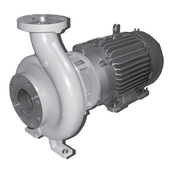
2 General Information 2 General Information 2.1 Pump description Model Pump Description Size Groups No. of Sizes This model has five (5) hydraulic pump sizes. It has a casing which is ANSI B73 dimensionally compliant and open im- peller design. 3196 CC This model has two (2) pump sizes. -
Page 13: Nameplate Information
2.3 Nameplate information Model Casing Impeller the casing feet as well as the motor feet for solid by a PTFE ring. The impeller is the support. same as used in the CV 3196 with the exception it has an anti-rotation option. The 3196 CC, CV 3196 CC, and 3796 use the Frame Adapter - The frame adapters for same seal chambers. -
Page 14: Storage Requirements
2.4 Receiving the pump 2.4.1 Storage requirements Short Term: (Less than 6 months) Goulds normal packaging procedure is designed to protect the pump during shipping. Upon receipt, store in a covered and dry location. Long Term: (More than 6 months) Preservative treatment of machined surfaces will be required. Rotate shaft several times every 3 months. - Page 15 2.4 Receiving the pump Figure 5: Proper lifting of pump using slings 3196CC Installation, Operation and Maintenance Instructions...
-
Page 16: Installation
3 Installation 3 Installation 3.1 Baseplate inspection Remove all equipment. Completely clean the underside of baseplate. It is sometimes necessary to coat the underside of the baseplate with an epoxy primer. This may have been purchased as an option. Remove the rust preventative solution from the machined pads with an appropriate solution. 3.2 Site / foundation A pump should be located near the supply of liquid and have adequate space for operation, mainte- nance, and inspection. -
Page 17: Level Baseplate
3.3 Level baseplate Figure 7: J type foundation bolts 3.3 Level baseplate 3.3.1 Fabricated steel Place two sets of wedges or shims on the foundation, one set on each side of every foundation bolt (Fig. 8 & 9). The wedges should extend 20mm | .75 in. to 40mm | 1.50 in. above foundation, to al- low for adequate grouting. - Page 18 3.3 Level baseplate Figure 9: 3196CC Installation, Operation and Maintenance Instructions...
-
Page 19: Baseplate-Leveling Worksheet
3.4 Baseplate-leveling worksheet 3.4 Baseplate-leveling worksheet Level measurements 1)____________________ 2)____________________ 3)____________________ 4)____________________ 5)____________________ 6)____________________ 7)____________________ 8)____________________ 9)____________________ 10)___________________ 11)___________________ 12)___________________ 13)___________________ 14)___________________ 15)___________________ 16)___________________ 17)___________________ 18)___________________ 3196CC Installation, Operation and Maintenance Instructions... -
Page 20: Grout Baseplate
3.5 Grout baseplate 3.5 Grout baseplate Clean areas of baseplate that will contact grout. Do not use oil-based cleaners because grout will not bond to it. Refer to grout manufacturer's instructions. Build dam around foundation. Thoroughly wet foundation (Fig. 10). Figure 10: Pour grout through grout hole in baseplate, up to level of dam. -
Page 21: Piping
3.6 Piping 3.6 Piping 3.6.1 General Guidelines for piping are given in the "Hydraulic Institute Standards" available from: Hydraulic Institute, 9 Sylvan Way, Parsippany, NJ 07054-3802 and must be reviewed prior to pump installation. WARNING: Never draw piping into place by forcing at the flanged connections of the pump. This may im- pose dangerous strains on the unit and cause misalignment between pump and driver. -
Page 22: Suction Piping
3.6 Piping Figure 13: Incorrect Do not connect piping to pump until grout has hardened and pump and driver hold- down bolts have been tightened. It is suggested that expansion loops or joints, if used, be properly installed in suction and/or discharge lines when handling liquids at elevated temperatures, so linear expan- sion of piping will not draw pump out of alignment (Fig. - Page 23 3.6 Piping Figure 14: Correct Figure 15: Incorrect Use suction pipe one or two sizes larger than the pump suction, with a reducer at the suction flange. Suction piping should never be of smaller diameter than the pump suction. Reducers should be eccentric at the pump suction flange with sloping side down and horizontal side at the top (Fig.
- Page 24 3.6 Piping Figure 16: CAUTION: Pump must never be throttled on suction side. Suction strainers, when used, must have a net ''free area" of at least three times the suction pipe area. Separate suction lines are recommended when more than one pump is operating from the same source of supply.
-
Page 25: Discharge Piping
3.6 Piping Figure 18: Suction Lift Conditions Suction pipe must be free from air pockets. Suction piping must slope upwards to pump. All joints must be air tight. A means of priming the pump must be provided, such as a foot valve, except for the 3796 self priming pump. -
Page 26: Final Piping Check
3.7 Final piping check Cushioning devices should be used to protect the pump from surges and water hammer if quick- closing valves are installed in system. 3.7 Final piping check After connecting the piping to pump: Rotate shaft several times by hand to be sure that there is no binding and all parts are free. Check alignment, per the alignment procedure outlined previously to determine absence of pipe strain. -
Page 27: Operation
4 Operation 4 Operation 4.1 Preparation for Start-up 4.2 Checking rotation CAUTION: Serious damage may result if pump is run in the wrong rotation. Unlock driver power. Make sure everyone is clear. Jog driver just long enough to determine direction of rotation. Rotation must correspond to arrow on bearing housing. - Page 28 4.2 Checking rotation Service Temperature 3196 LF3196 3796 CV3196 MTX/LTX XLTX/X17 STXMTX/LTX STXMTX/L MTX/LTX XLTX inches mm inches mm inches mm inches mm ches ches -20 to 150°F (-29 to 0.005 0.13 0.008 0.20 0.015 0.38 0.015 0.38 0.06 1.52 0.01 0.38 66°C) Up to 175°F (79°C)
- Page 29 4.2 Checking rotation External Flush - A clean, cool compatible liquid is injected from an outside source directly into the seal gland. The flushing liquid must be at a pressure of 5-15 psi (0.35-01 kg/cm2 ) greater than the seal chamber pressure. Injection rate should be ½-2 GPM (2-8 LPM). Other methods may be used which make use of multiple gland connections and/or seal chamber connections.
-
Page 30: Priming Pump
4.2 Checking rotation Figure 21: Install the gland halves and evenly hand tighten the nuts. Connection of Sealing Liquid: If the stuffing box pressure is above atmospheric pressure and the pumpage is clean, normal gland leak- age of 40-60 drops per minute is usually sufficient to lubricate and cool the packing and sealing liquid is not required. - Page 31 4.2 Checking rotation Figure 22: Open air vents on the suction and discharge piping until water flows out. Close the vent valves. Suction Supply Below Pump (Except 3796) A foot valve and outside source of liquid may be used to prime the pump. Outside source of liquid can come from a priming pump, pressurized discharge line, or other outside supply (Fig.
- Page 32 4.2 Checking rotation Figure 24: Figure 25: NOTICE: Model 3796 is a self-priming pump and does not require the use of a foot valve in the suction line. Refer to the pump's performance curve to determine the time required for priming. Close discharge valve and open air vents in casing.
-
Page 33: Other Methods Of Priming
4.3 Starting pump Open valve in outside supply line until only liquid escapes from vent valves. Close the vent valves and then the outside supply line. Suction Supply Below Pump - 3796 NOTICE: The 3796 is a self priming pump and does not require manual priming prior to start-up (except for the initial charge). -
Page 34: Operation
4.4 Operation CAUTION: Observe pump for vibration levels, bearing temperature and excessive noise. If normal levels are exceeded, shut down and resolve. 4.4 Operation 4.4.1 General considerations Always vary capacity with regulating valve in the dis charge line. Never throttle flow from the suction side. -
Page 35: Preventive Maintenance
5 Preventive Maintenance 5 Preventive Maintenance 5.1 General comments A routine maintenance program can extend the life of your pump. Well maintained equipment will last longer and require fewer repairs. You should keep maintenance records, this will help pinpoint potential causes of problems. -
Page 36: Packed Stuffing Box
5.8 Impeller clearance setting The life of a mechanical seal depends on various factors such as cleanliness of the liquid handled and its lubricating properties. Due to the diversity of operating conditions it is, however, not possible to give definite indications as to its life. WARNING: Never operate the pump without liquid supplied to mechanical seal. - Page 37 5.9 Feeler gauge method (all but CV) Figure 26: Add to this measurement the impeller clearance required from Table 4: Impeller Clearances on page Select four (4) sets of shim(s) (329B) equal to this thickness. NOTICE: In some cases, finding an exact match may not be possible. In this case, select the next clos- est size greater.
-
Page 38: Feeler Gauge Method (Cv)
5.10 Feeler gauge method (CV) 5.10 Feeler gauge method (CV) Loosen the motor locking bolts (370B). Begin tightening the jacking bolts (370D) evenly, pushing the motor (338) away from the pump until the impeller contacts the cover. Turn shaft to ensure contact is made. Use a feeler gauge to measure the gap between the motor (338) face and the frame adapter (Fig. -
Page 39: Troubleshooting
5.11 Troubleshooting 5.11 Troubleshooting Problem Probable Cause Remedy No liquid delivered. Pump not primed. Reprime pump, check that pump and suc- tion line are full of liauid. Suction line cloqqed. Remove obstructions. Impeller cloqqed with foreiqn material. Back flush pump to clean impeller. Wrong direction of rotation. -
Page 40: Disassembly & Reassembly
6 Disassembly & reassembly 6 Disassembly & reassembly 6.1 Required tools • Wrenches • Screwdriver • Lifting Sling • Rubber Mallet • Dial Indicator • Torque Wrench with Sockets • Allen Wrenches • Micrometer • Cleaning Agents • Feeler Gauges •... - Page 41 6.2 Disassembly Place sling from hoist through frame adapter (108) or frame and around bottom of motor (Fig. 29). Figure 29: Remove motor foot hold down bolts (see Figure 29: on page 39). Remove casing bolts (370) (see Figure 29: on page 39).
-
Page 42: Removal Of Impeller
6.2 Disassembly 6.2.1 Removal of impeller WARNING: Never apply heat to remove an impeller. The use of heat may cause an explosion due to trap- ped fluid, resulting in severe physical injury and property damage. WARNING: Wear heavy work gloves when handling impellers (101) as sharp edges may cause physical injury. - Page 43 6.2 Disassembly Figure 31: Rotate the impeller clockwise (viewed from the impeller end of the shaft), raising the wrench. Quickly turn the impeller counterclockwise (viewed from the impeller end of the shaft), impacting the wrench handle until the impeller loosens (Fig. 30). Remove impeller 0-ring (412A) and discard.
-
Page 44: Removal Of Seal Chamber Cover (Mechanical Seal)
6.3 Removal of seal chamber cover (mechanical seal) Figure 33: NOTICE: It is recommended that the motor foot be clamped to the workbench when using this method to remove the impeller. 6.3 Removal of seal chamber cover (mechanical seal) Remove gland stud nuts (355). Remove seal chamber stud nuts (370H). -
Page 45: Removal Of Stuffing Box Cover (Packed Box)
6.4 Removal of stuffing box cover (packed box) Figure 35: NOTICE: Be careful not to damage the stationary portion of the mechanical seal. It is seated in the gland bore. 6.4 Removal of stuffing box cover (packed box) Remove gland stud nuts (355), and gland (107). Remove stuffing box cover stud nuts (370H). -
Page 46: Remove Frame Adapter
6.5 Remove frame adapter Figure 37: Remove packing (106) and lantern ring (105) from stuffing box cover (184). No lantern ring is pro- vided with self-lubricating graphite packing. Figure 38: 6.5 Remove frame adapter Remove motor lock bolts (3708) and shims. Carefully, remove frame adapter (108) (Fig. -
Page 47: Remove Inboard Labyrinth Oil Seal (333A)
6.6 Remove inboard labyrinth oil seal (333A) Figure 39: WARNING: Frame adapter (108) is heavy. Use proper lifting equipment when handling. 6.6 Remove inboard labyrinth oil seal (333A) It is an O-ring fit into the bearing frame (228A) for STX, frame adapter (108) for MTX, LTX, XLT-X and X17. -
Page 48: Inspections
6.7 Inspections 6.7 Inspections The pump parts must be inspected to the following criteria before they are reassembled to insure the pump will run properly. Any part not meeting the required criteria should be replaced. NOTICE: Clean parts in solvent to remove oil, grease or dirt. Protect machined surfaces against damage during cleaning. -
Page 49: Impeller
6.7 Inspections Figure 43: Localized wear or grooving greater than 1/8 in. (2 mm) deep. Pitting greater than 1/8 in. (2 mm) deep. Inspect case gasket seat surface for irregularities. 6.7.2 Impeller Inspect impeller (101) vanes for damage. Replace if grooved deeper that 1/16 in. (1.6 mm) or if worn evenly more than 1/32 in. -
Page 50: Seal Chamber/Stuffing Box Cover
6.7 Inspections Figure 45: Inspect leading and trailing edges of the vanes for cracks, pitting, and erosion or corrosion dam- age. (Area "c" in Fig. 44 & 45). NOTICE: For CV 3196 impeller, the face of the impeller is cast, not machined. The face runout need not be checked. - Page 51 6.7 Inspections Figure 47: Figure 48: Replace if there is any pitting or wear greater than 1/8 in. (2 mm) deep. 3196CC Installation, Operation and Maintenance Instructions...
-
Page 52: Frame Adapter
6.8 Reassembly 6.7.4 Frame adapter Check frame adapter (108) for cracks or excessive corrosion damage. Replace if any of these conditions exist, see Figure 44: on page Make sure gasket surface is clean. Figure 49: 6.8 Reassembly Refer to following table for torque values while reassembling pump. Table 5: Maximum Torque Values in ft.-lb. -
Page 53: Reassembly
6.9 Reassembly with 300 lb. Casing flanges Material Specification Ductile Iron Casing with A Alloy Casing with (30455) Ductile Iron and Alloy Cas- 307 Grade B casing bolts ings with A193 grade 87 cas- F593 Grade 1 or ing bolts (31655 F593) Grade 2 casinn bolts Frame... - Page 54 6.9 Reassembly Figure 51: Install inboard labyrinth oil seal (333A) into adapter (108) / bearing frame (228). It is an O-ring fit. Position the labyrinth seal drain slots at the bottom (6 o'clock) position. (Fig. 51). Figure 52: NOTICE: For detailed labyrinth seal installation instructions, see Appendix, Labyrinth Seal Installation In- structions.
- Page 55 6.9 Reassembly Figure 53: Install seal chamber cover or backplate (184) with nuts (370H) Fig. 52). Figure 54: Check seal chamber cover run-out. Rotate indicator through 360 degrees. If total indicator reading is greater than 0.005 in. (.13 mm), determine cause and correct before proceeding (Fig. 53). Install shaft sleeve (126) if used (Fig.
- Page 56 6.9 Reassembly Figure 55: Figure 56: STX, MTX, LTX - Install impeller (101) with 0-ring (Fig. 54 & 55). 10. Put wrench on shaft to stop rotation. When impeller (101) makes firm contact with sleeve (126), turn the wrench counterclockwise (viewed from impeller end of shaft) and slam it down. A few sharp raps will tighten impeller (101) properly (Fig.
- Page 57 6.9 Reassembly Figure 57: NOTICE: The face of the CV 3196 CC impeller is not machined. Checking the face runout on the CV 3196 CC impeller is not required. Pumps with Mechanical Seals For pumps with non-cartridge mechanical seals, it is necessary to temporarily install spacer shims (329B) before scribing shaft / sleeve.
- Page 58 6.9 Reassembly Figure 59: NOTICE: If installing a cartridge mechanical seal, the shaft or sleeve does not need to be marked. The seal is self setting. 17. Check impeller (101) runout. Check vane tip to vane tip. If total indicator reading is greater than 0.005 in.
- Page 59 6.9 Reassembly Figure 61: 19. Remove the seal chamber cover or the backplate (Fig. 60). Figure 62: Install mechanical seal on shaft (122) or shaft sleeve (126) per seal manufacturer's instructions. In- stall shaft sleeve (126) if used (with seal). NOTICE: Anti-galling compound can be applied to the sleeve bore to aid in disassembly.
- Page 60 6.9 Reassembly Figure 63: 22. Install stationary seat into gland (107) per seal manufacturer's instructions. 23. Slide gland (107) with stationary seat over shaft, up to adapter face (Fig . 61). WARNING: Wear a heavy set of work gloves when handling impeller (101) as sharp edges may cause physical injury.
- Page 61 6.9 Reassembly Figure 65: 26. 13. Install gland (107) with nuts (355) (Fig. 65). Figure 66: For outside mounted seals: 27. Install the mechanical seal on the shaft (122) or sleeve, if used (126) per the seal manufacturer's instructions. Install the sleeve with the seal, if used. 28.
- Page 62 6.9 Reassembly Figure 67: 29. Install the seal chamber or backplate (184) with hex nuts (370H). Be sure that the gland studs line up with the holes in the gland (Fig. 67). Figure 68: 30. Install the impeller (101) with a new 0-ring (412A). Put the wrench and on the shaft. When the im- peller makes firm contact with the sleeve, raise the shaft wrench (counterclockwise when viewed from the impeller end of the shaft) and slam it down (clockwise when viewed from the impeller end of the shaft).
- Page 63 6.9 Reassembly Figure 69: NOTICE: Be sure to use a properly balanced impeller. 32. Install the gland (107) with hex nuts (355). Pumps With Packing: 33. Install stuffing box cover (184) with nuts (370H) (Fig 70). Figure 70: 34. Install shaft sleeve (126) (Fig. 71). Figure 71: 3196CC Installation, Operation and Maintenance Instructions...
- Page 64 6.9 Reassembly NOTICE: Anti-galling compound can be applied to the sleeve bore to aid in disassembly. NOTICE: Make sure sleeve is fully seated. WARNING: Wear a heavy set of work gloves when handling impeller (101) as sharp edges may cause in- jury.
-
Page 65: All Models Stx, Mtx, Ltx, Xlt-X, X17
6.10 All models STX, MTX, LTX, XLT-X, X17 NOTICE: The face of the CV 3196 impeller is not machined. Checking the face runout on the CV 3196 is note required. 37. Install packing and gland according to 4 Operation on page 6.10 All models STX, MTX, LTX, XLT-X, X17 6.11 Reinstall Back Pull-Out Assembly WARNING:... -
Page 66: Impeller Adjustment
6.12 Impeller Adjustment 6.12 Impeller Adjustment Once the pump has been re-assembled, it is important to perform the correct impeller adjustment prior to start-up. Refer to 5.8 Impeller clearance setting on page 34 for the proper procedure. 6.13 Assembly Troubleshooting Symptom Cause Remedy... -
Page 67: Parts List With Materials Of Construction
6.14 Parts list with materials of construction PFA Lined Steel 6944 PFA Lined 316SS 6947 PFA Lined Ductile 9639 Iron Fasteners/Plugs Material Goulds Pumos Material Code ASTM Carbon Steel 2210 A307Gr.B. Stainless Steel 2228 F593Gr1 316 Stainless Steel 2229 F593Gr2 6.14 Parts list with materials of construction Item Part Description... -
Page 68: Model 3196 Cross Sectional
6.15 Model 3196 Cross Sectional 6.15 Model 3196 Cross Sectional 3196CC Installation, Operation and Maintenance Instructions... -
Page 69: Model Cv 3196 Cross Sectional
6.16 Model CV 3196 Cross Sectional 6.16 Model CV 3196 Cross Sectional 6.17 Model 3796 Cross Sectional 3196CC Installation, Operation and Maintenance Instructions... -
Page 70: Spare Parts
7 Spare Parts 7 Spare Parts When ordering spare parts, always state Goulds Serial No. and indicate part name and item number from relevant sectional drawing. It is imperative for service reliability to have a sufficient stock of readily available spares. 7.1 Recommended spare parts •... -
Page 71: Appendix
8 Appendix 8 Appendix 8.1 Labyrinth Seal Installation Instructions 8.1.1 Description of Operation The labyrinth oil seal serves two functions. The first being to exclude environmental contamination from the power-end. This is accomplished with a series of tight clearance fits between the stationary and rotor. Any water that manages to enter the seal is eliminated from the seal through a drain slot located at the six o'clock position when installed. - Page 72 8.2 Installation Procedures NOTICE: During start-up when the parts of the labyrinth oil seal establish a voluntary running clearance, a small amount of wear is experienced as the parts are in contact. This wear produces a car- bon filled PTFE residue, visible at the outside diameter of the seal and at the drain slot. This is the result of the two surfaces being smoothed, similar to burnishing.
- Page 73 Visit our website for the latest version of this document and more information: www.gouldspumps.com ITT - Goulds Pumps Vertical Products Operation 3951 Capitol Avenue City of Industry, CA 90601-1734 Form IOM.3196CC.en-US.2021-08 ©2021 ITT Corporation The original instruction is in English. All non-English instructions are translations of the original instruction.
Need help?
Do you have a question about the Goulds Pumps 3196CC and is the answer not in the manual?
Questions and answers