
Related Manuals for ITT Goulds Pumps i-FRAME 3640


Summary of Contents for ITT Goulds Pumps i-FRAME 3640
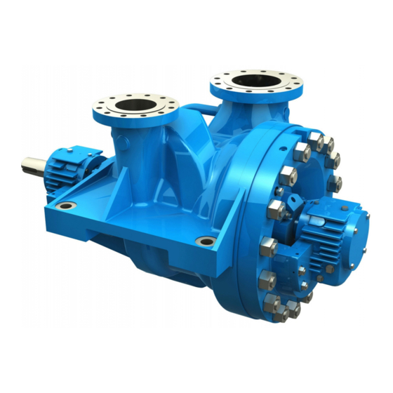
- Page 1 Installation, Operation, and Maintenance Manual 3640 i-FRAME API Type BB2 2-Stage / ISO 13709 2nd Ed. API 11th Ed.
-
Page 3: Table Of Contents
Table of Contents Table of Contents 1 Introduction and Safety ............................ 4 1.1 Introduction..............................4 1.1.1 Requesting other information ......................4 1.2 Safety ................................ 4 1.2.1 Safety terminology and symbols ..................... 5 1.2.2 Environmental safety........................6 1.2.3 User safety ............................6 1.2.4 Ex-approved products ........................ - Page 4 Table of Contents 4.6.2 Suction-piping checklist......................... 33 4.6.3 Discharge piping checklist......................35 4.6.4 Bypass-piping considerations ....................... 35 4.6.5 Auxiliary-piping checklist ....................... 36 4.6.6 Final piping checklist ........................36 5 Commissioning, Startup, Operation, and Shutdown ................... 37 5.1 Preparation for startup..........................37 5.2 Remove the coupling guard ........................
- Page 5 8.1 Parts list..............................119 8.2 Cross-sectional diagrams........................125 8.2.1 ..............................130 9 Local ITT Contacts ............................131 9.1 Regional offices............................. 131 3640 i-FRAME API Type BB2 2-Stage / ISO 13709 2nd Ed. API 11th Ed. Installation, Operation, and Maintenance Man-...
-
Page 6: Introduction And Safety
For instructions, situations, or events that are not consid- ered in this manual or in the sales documents, please contact the nearest ITT representative. Always specify the exact product type and identification code when requesting technical information or spare parts. -
Page 7: Safety Terminology And Symbols
Risk of injury and/or property damage. Operating a pump in an inappropriate application can cause over pressurization, overheating, and/or unstable operation. Do not change the service application without the approval of an authorized ITT representative. 1.2.1 Safety terminology and symbols... -
Page 8: Environmental Safety
WARNING: If the product has been contaminated in any way, such as from toxic chemicals or nuclear radi- ation, do NOT send the product to ITT until it has been properly decontaminated and advise ITT of these conditions before returning. - Page 9 1.2 Safety • Always keep the work area clean. • Pay attention to the risks presented by gas and vapors in the work area. • Avoid all electrical dangers. Pay attention to the risks of electric shock or arc flash hazards. •...
-
Page 10: Ex-Approved Products
Personnel requirements These are the personnel requirements for Ex-approved products in potentially explosive atmospheres: • All work on the product must be carried out by certified electricians and ITT-authorized mechanics. Special rules apply to installations in explosive atmospheres. • All users must know about the risks of electric current and the chemical and physical characteristics of the gas, the vapor, or both present in hazardous areas. -
Page 11: Monitoring Equipment
Compliance is fulfilled only when you operate the unit within its intended use. Do not change the condi- tions of the service without the approval of an ITT representative. When you install or maintain explosion proof products, always comply with the directive and applicable standards (for example, IEC/EN 60079–... -
Page 12: Product Warranty
All service and repair work is done by ITT-authorized personnel. • Genuine ITT parts are used. • Only Ex-approved spare parts and accessories authorized by ITT are used in Ex-approved prod- ucts. Limitations The warranty does not cover faults caused by these situations: •... -
Page 13: Transportation And Storage
2 Transportation and Storage 2 Transportation and Storage 2.1 Inspect the delivery 2.1.1 Inspect the package Inspect the package for damaged or missing items upon delivery. Note any damaged or missing items on the receipt and freight bill. File a claim with the shipping company if anything is out of order. If the product has been picked up at a distributor, make a claim directly to the distributor. - Page 14 2.2 Transportation guidelines • Lifting and handling heavy equipment poses a crush hazard. Use caution during lifting and handling and wear appropriate Personal Protective Equipment (PPE, such as steel- toed shoes, gloves, etc.) at all times. Seek assistance if necessary. •...
-
Page 15: Storage Guidelines
Treat bearing and machined surfaces so that they are well preserved. Refer to the drive unit and cou- pling manufacturers for their long-term storage procedures. For questions about possible long-term storage treatment services, please contact your local ITT sales representative. -
Page 16: Product Description
3 Product Description 3 Product Description 3.1 General description Product description The Model 3640 i-FRAME is a horizontal centrifugal pump that meets the latest editions of API 610 and ISO 13709 and has these characteristics: • High-pressure • High-temperature • Two-stage •... -
Page 17: General Description I-Alert®2 Equipment Condition Monitor
3.2 General description i-ALERT®2 Equipment Condition Monitor Power end The power end has these characteristics: • Carbon steel bearing housings are standard. • The oil level is viewed through a sight glass. • Constant-level oilers and labyrinth seals are standard. •... -
Page 18: Nameplate Information
3.3 Nameplate information ® Monitor option available. The i-ALERT 2 monitor allows customers to identify potential problems before they become costly failures. It tracks vibration, temperature and run-time hours and wirelessly syncs the ® data with a smart phone or tablet the i-ALERT 2 mobile app. - Page 19 3.3 Nameplate information Nameplate field Explanation Rated pump speed, in revolutions per minute HYDRO PRESS Hydrostatic pressure at 100°F, in pounds per square inch MAX. DES. WORKING PRESS Maximum working pressure at temperature °F, in pounds per square inch Serial number of the pump CONT./ITEM NO.
- Page 20 Use of equipment unsuitable for the environment can pose risks of ignition and/or explosion. Ensure the pump driver and all other auxiliary components meet the required area classifica- tion at the site. If they are not compatible, do not operate the equipment and contact an ITT representative before proceeding.
-
Page 21: Installation
Electrical connections must be made by certified electricians in compliance with all inter- national, national, state and local regulations. • Supervision by an authorized ITT representative is recommended to ensure proper instal- lation. Improper installation may result in equipment damage or decreased performance. 4.1.1 Pump location guidelines... -
Page 22: Foundation Requirements
4.1 Pre-installation 4.1.2 Foundation requirements Requirements • The foundation must weigh not less than three times the combined weight of the pump, driver, baseplate and auxiliaries. • Provide a flat, substantial concrete foundation in order to prevent strain and distortion when you tighten the foundation bolts. -
Page 23: Baseplate-Mounting Procedures
4.2 Baseplate-mounting procedures J-type bolts Item Description Baseplate Foundation Bolt Figure 9: J-type bolts 4.2 Baseplate-mounting procedures 4.2.1 Prepare the baseplate for mounting This procedure assumes you have a basic knowledge of baseplate and foundation design and installa- tion methods. Follow industry-standard procedures, such as API RP 686/ PIP REIE 686, or this proce- dure before you grout the baseplate. -
Page 24: Prepare The Foundation For Mounting
4.2 Baseplate-mounting procedures 4.2.2 Prepare the foundation for mounting Chip the top of the foundation to a minimum of 25.0 mm | 1.0 in. in order to remove porous or low- strength concrete. If you use a pneumatic hammer, make sure that it does not contaminate the surface with oil or other moisture. -
Page 25: Install The Pump, Driver, And Coupling
4.3 Install the pump, driver, and coupling The baseplate will rest on top of the foundation on the jackscrews provided on the baseplate. Adjust the leveling jackscrews, located adjacent to the foundation bolt holes, until the baseplate rests 25 to 50 mm | 1 to 2 in. above the foundation in order to allow for adequate grouting. This provides even support for the baseplate after grouting. -
Page 26: Alignment Checks
The specified permitted reading values are valid only at operating temperature. For cold set- tings, other values are permitted. The correct tolerances must be used. Failure to do so can result in misalignment. Contact ITT for further information. IMPORTANT •... -
Page 27: Alignment Measurement Guidelines
4.4 Pump-to-driver alignment 4.4.3 Alignment measurement guidelines Guideline Explanation Rotate the pump coupling half and the driver coupling half together This prevents incorrect measurement. so that the indicator rods have contact with the same points on the driver coupling half. Move or shim only the driver in order to make adjustments. -
Page 28: Perform Angular Alignment For A Horizontal Correction
4.4 Pump-to-driver alignment When the Then... reading val- ue is... Negative The coupling halves are farther apart at the bottom than at the top. Perform one of these steps: • Add shims in order to raise the feet of the driver at the shaft end. •... -
Page 29: Perform Parallel Alignment For A Vertical Correction
4.4 Pump-to-driver alignment Figure 14: Example of incorrect horizontal alignment (top view) Repeat the previous steps until the permitted reading value is achieved. 4.4.7 Perform parallel alignment for a vertical correction Refer to the alignment table in "Permitted indicator values for alignment checks" (see Table of Contents for location of table) for the proper cold alignment value based on the driver temperature rise and the pump operating temperature. -
Page 30: Perform Parallel Alignment For A Horizontal Correction
The specified permitted reading values are valid only at operating temperature. For cold set- tings, other values are permitted. The correct tolerances must be used. Failure to do so can result in misalignment. Contact ITT for further information. 4.4.8 Perform parallel alignment for a horizontal correction Refer to the alignment table in "Permitted indicator values for alignment checks"... -
Page 31: Perform Complete Alignment For A Horizontal Correction
4.5 Grout the baseplate Set the angular and parallel dial indicators to zero at the top-center position (12 o’clock) of the driver coupling half (Y). Rotate the indicators to the bottom-center position (6 o’clock). Record the indicator readings. Make corrections according to the separate instructions for angular and parallel alignment until you obtain the permitted reading values. - Page 32 4.5 Grout the baseplate Item Description Baseplate Foundation Sleeve Bolt Grout Figure 17: Pour grout into baseplate Fill the remainder of the baseplate with grout, and allow the grout to set for at least 48 hours. Item Description Baseplate Foundation Sleeve Bolt Grout...
-
Page 33: Piping Checklists
4.6 Piping checklists Tighten the foundation bolts. Recheck the alignment. 4.6 Piping checklists 4.6.1 General piping checklist Precautions WARNING: • Risk of premature failure. Casing deformation can result in misalignment and contact with rotating parts, causing excess heat generation and sparks. Flange loads from the piping system, including those from the thermal expansion of the piping, must not exceed the limits of the pump. - Page 34 4.6 Piping checklists Checklist Check Explanation/comment Checked Check that all piping is supported in- • Strain on the pump dependently of, and lined up naturally • Misalignment between the pump and the drive unit with, the pump flange. See Alignment criteria for pump flanges.
-
Page 35: Suction-Piping Checklist
4.6 Piping checklists 4.6.1.1 Fastening WARNING: Risk of serious personal injury or property damage. Fasteners such as bolts and nuts are criti- cal to the safe and reliable operation of the product. Ensure appropriate use of fasteners during installation or reassembly of the unit. •... - Page 36 4.6 Piping checklists Check Explanation/comment Checked It is recommended that a commissioning Suction strainers help to prevent debris from entering (temporary) suction strainer be used. the pump After commissioning it is recommended an Recommended commissioning (temporary) strainer operating (permanent) suction strainer be mesh size: used.
-
Page 37: Discharge Piping Checklist
When to install a minimum-flow orifice You can size and install a minimum-flow orifice in a bypass line in order to prevent bypassing excessive flows. Consult your ITT representative for assistance in sizing a minimum-flow orifice. When a minimum-flow orifice is unavailable Consider an automatic recirculation control valve or solenoid-operated valve if a constant bypass (mini- mum-flow orifice) is not possible. -
Page 38: Auxiliary-Piping Checklist
4.6 Piping checklists 4.6.5 Auxiliary-piping checklist Precautions CAUTION: • Risk of heat generation, seal failure, and possible physical injury. Sealing systems that are not self-purging or self-venting, such as plan 23, require manual venting prior to oper- ation. • Running a mechanical seal dry, even for a few seconds, can cause seal failure and physi- cal injury. -
Page 39: Commissioning, Startup, Operation, And Shutdown
5 Commissioning, Startup, Operation, and Shutdown 5 Commissioning, Startup, Operation, and Shutdown 5.1 Preparation for startup WARNING: • Risk of serious physical injury or death. Exceeding any of the pump operating limits (e.g. - pressure, temperature, power, etc.) could result in equipment failure, such as explosion, seizure, or breach of containment. -
Page 40: Remove The Coupling Guard
5.2 Remove the coupling guard NOTICE: • Verify the driver settings before you start any pump. Refer to the applicable drive equip- ment IOMs and operating procedures. • Excessive warm-up rates can cause equipment damage. Ensure the warm-up rate does not exceed 1.4°C | 2.5°F per minute. -
Page 41: Check The Rotation
5.3 Check the rotation Slightly spread the bottom apart. Lift upwards. 5.3 Check the rotation WARNING: • Starting the pump in reverse rotation can result in the contact of metal parts, heat genera- tion, and breach of containment. Ensure correct driver settings prior to starting any pump. •... -
Page 42: Coupling Guard Assembly
5.4 Couple the pump and driver Slide the rotor towards the outboard end of the motor as far as it will go and mark the shaft at the motor frame. Slide the rotor towards the inboard end of the motor as far as it will go and mark the shaft again. - Page 43 5.4 Couple the pump and driver • Refer to driver/coupling/gear manufacturer's installation and operation manuals (IOM) for specific instructions and recommendations. Parts required Part No. Description Part No. Description 569E Hex head bolt (Qty 3) 534A Washer (Qty 4) 501B Guard (Qty 2) 534B Retainer (Qty 3)
- Page 44 5.4 Couple the pump and driver Align the pump cover (234A) to the outboard end cover (160) so the holes in the pump cover align with the holes in the outboard end cover. Replace the four outboard end cover bolts (371D) and torque to the value shown in the Assem- bly referencesThis section contains reference information for reassembly procedures..
- Page 45 5.4 Couple the pump and driver 534A 569E 570E 534B 534A Figure 22: Captured hardware component assembly Install the bolt retainer (534B) over the exposed end of the bolt, and the U-Nut (570E) into the slot in the coupling guard if it was not done from the factory. Thread bolt (569E) into the U-Nut (570E) and tighten firmly.
- Page 46 5.4 Couple the pump and driver 234B Item Description Driver Annular groove Figure 24: Align driver end guard half with annular groove in endplate Repeat Steps 3. through 5. for the rear end of the coupling guard half, except that you hand tighten the bolt.
-
Page 47: Bearing Lubrication
5.5 Bearing lubrication 5.5 Bearing lubrication Precautions WARNING: Risk of explosive hazard and premature failure from sparks and heat generation. Ensure bearings are properly lubricated prior to startup. Pumps are shipped without oil You must lubricate oil-lubricated bearings at the job site. Ring oil lubrication Ring oil-lubricated bearings are standard. -
Page 48: Lubricating-Oil Requirements
5.5 Bearing lubrication All frames in this table use a Watchdog Oiler, which has a capacity of 118 ml | 4 oz. Drive End Bearing Housing Non Drive End Bearing Hous- Thrust Bear- Oil Volume ing Oil Volume Size Radial Bearing ounces ounces Sleeve... -
Page 49: Replace The Oil Filter
5.5 Bearing lubrication Ring oil-lubricated pumps are supplied with an oiler that maintains a constant oil level in the bearing housing. Fill the oil reservoir in the bearing frame: Fill the bearing chamber through the main body of the Watchdog until it reaches the optimum fluid level visible in the bullseye sight. - Page 50 5.5 Bearing lubrication 113Q 113Q 113Q 113Q 550A 550A 1. Non-filter side 2. Filter side 3. Shaft rotation C.W. 4. Shaft rotation C.C.W. Figure 27: Oil filter and plug removal Unscrew the filter (550A), part number K08174A from the plug (113Q), part number K06818A. Keep the plug (113Q) and discard the old filter (550A).
-
Page 51: Lubricate The Bearings With Pure Or Purge-Oil Mist (Optional)
5.5 Bearing lubrication 428E 428E 550A Figure 29: Filter kit Screw the new filter (550A) into the existing plug (113Q) and install the new o-rings (428E) to the filter side plug (113Q) and the non-filter side plug (113Q). See Figure 30: New filter installation on page 113Q 113Q... -
Page 52: Lubricate The Bearings With Pressurized Lubrication
5.5 Bearing lubrication Note that only one of the two connection ports in the radial bearing housing is used (immediately above the single row radial bearing). You must connect to both connections on the thrust bearing housing, because there are two rows of bearings. 551E 133H 133H... -
Page 53: Convert To Oil-Mist Lubrication
5.5 Bearing lubrication Item Description Thrust bearing oil inlet Sleeve bearing oil inlet, thrust Sleeve bearing oil inlet, radial Figure 32: Oil feed location Item Description Thrust bearing housing oil drain Radial bearing housing oil drain Figure 33: Oil drain locations 5.5.8 Convert to oil-mist lubrication NOTICE: Make sure that pipe threads are clean and apply thread sealant to plugs and fittings. -
Page 54: Thrust Bearing Cooling Fan (Optional)
5.5 Bearing lubrication NOTICE: In both housings install bearing end cover (160) designed for oil mist. You can convert from ring-oil lubrication to oil-mist lubrication in pumps with ball bearing construction. The radial and thrust end bearing housings (134) have pre-drilled connections for oil mist: •... -
Page 55: Install The Fan Guard
5.5 Bearing lubrication 234D 392B 234E 332C 785D 371C 569F 534D 222V 570F 534E 1. Fan Detail 2. Guard Detail Figure 34: Cooling fan assembly 5.5.10 Install the fan guard Is the pump endplate (234D) already installed? If yes; install fan (392B) and tighten set screws (222V) and then proceed to step 2. If no;... -
Page 56: Shaft Sealing With A Mechanical Seal
5.6 Shaft sealing with a mechanical seal 5.6 Shaft sealing with a mechanical seal Precautions WARNING: The mechanical seal used in an Ex-classified environment must be properly certified. CAUTION: Running a mechanical seal dry, even for a few seconds, can cause seal failure and physical injury. -
Page 57: Pump Priming
5.8 Pump priming Seal flushing methods Table 1: You can use these methods in order to flush or cool the seal: Method Description Product flush Run the piping so that the pump pushes the pumped fluid from the casing and injects it into the seal gland. If necessary, an external heat exchanger cools the pumped fluid before it enters the seal gland. -
Page 58: Start The Pump
5.10 Start the pump Item Description Discharge isolation valve Check valve Suction isolation valve Figure 35: Suction supply above pump 5.10 Start the pump WARNING: Risk of equipment damage, seal failure and breach of containment. Ensure all flush and cool- ing systems are operating correctly prior to starting pump. -
Page 59: I-Alert®2 Equipment Health Monitor
5.11 i-ALERT®2 Equipment Health Monitor Stop the driver. Prime the pump again. Restart the driver. Monitor the pump while it is operating: Check the pump for bearing temperature, excessive vibration, and noise. If the pump exceeds normal levels, then shut down the pump immediately and correct the prob- lem. -
Page 60: Shut Down The Pump
5.13 Shut down the pump • For pumps with auxiliary piping, make sure that proper flows have been established and that the equipment is operating properly. • Establish baseline vibration readings in order to determine normal running conditions. If the unit is running roughly, then consult the factory. •... -
Page 61: Deactivate The I-Alert®2 Equipment Health Monitor
5.14 Deactivate the i-ALERT®2 Equipment Health Monitor ® 5.14 Deactivate the i-ALERT 2 Equipment Health Monitor NOTICE: Always deactivate the health monitor when the pump is going to be shut down for an extended period of time. Failure to do so will result in reduced battery life. NOTICE: Always reset the health monitor when the pump is started after maintenance, system change, or being shut down for an extended period of time. -
Page 62: Installing The Driver
5.16 Doweling the pump casing There are two methods for doweling the pump casing, depending on whether the pump is operated in an application with a low or high temperature differential between the ambient temperature during setup and the temperature of the pumped fluid. If the temperature differential is low the pump foot on the drive end of the pump will require taper pins installed to secure the pump to the pedestal. -
Page 63: Doweling For Low Differential Temperature Service
5.16 Doweling the pump casing 5.16.2 Doweling for low differential temperature service Use this method to dowel the drive end pump foot to the baseplate pedestal when there is not a high temperature differential between the ambient temperature during setup and the temperature of the pump- ed fluid. - Page 64 5.16 Doweling the pump casing NOTICE: • During installation verify the bolts (item 371D) are torqued properly. • During installation verify the taper pins (item 469E) are installed. 533C 469E 371D 463A 1. Drive end 2. Non drive end Item Description Part no.
- Page 65 5.16 Doweling the pump casing 372W 427A 533B Item Description Part No. Tighten lower hex nut 1/3 to 1/2 turn beyond hand tight to ensure Belleville washers are compressed. Stud 372W Hex nuts 427A Belleville washers Hardened flat washers 533B Figure 37: Pump foot mounting detail Tighten lower hex nut 1/3 to 1/2 turn beyond hand tight to ensure belleville washers are com- pressed.
-
Page 66: Maintenance
6 Maintenance 6 Maintenance 6.1 Maintenance schedule Maintenance inspections A maintenance schedule includes these types of inspections: • Routine maintenance • Routine inspections • Three-month inspections • Annual inspections Shorten the inspection intervals appropriately if the pumped fluid is abrasive or corrosive or if the envi- ronment is classified as potentially explosive. -
Page 67: Bearing Maintenance
Cartridge seals installed by the user require disengagement of the hold- ing clips prior to operation, allowing the seal to slide into place. If the seal has been installed in the pump by ITT, these clips have already been disengaged. Other mechanical seal types For other types of mechanical seals, refer to the instructions provided by the seal manufacturer for instal- lation and setting. -
Page 68: Disassembly
6.4 Disassembly Before you start the pump Check the seal and all flush piping. Mechanical seal life The life of a mechanical seal depends on the cleanliness of the pumped fluid. Due to the diversity of op- erating conditions, it is not possible to give definite indications as to the life of a mechanical seal. 6.4 Disassembly 6.4.1 Disassembly precautions WARNING:... -
Page 69: Prepare For Disassembly
6.4 Disassembly • Drill • Feeler gauges • Hex wrenches • Induction heater • Lifting sling • Micrometers (inside and outside) • Open end wrenches • Press • Soft face hammer • Spanner wrench • Spanning type puller • • Torque wrench with sockets •... -
Page 70: Disassemble The Radial End (Ball Bearing Pumps)
6.4 Disassembly Unbolt and remove the coupling spacer (235B). Follow the instructions provided by the coupling manufacturer for assistance. Remove the coupling guard pump endplate (234A). Remove the coupling nut (520) from the tapered shaft end on the pump. 10. Remove the coupling hub (233) from the pump. •... -
Page 71: Disassemble The Thrust End (Ball Bearing Pumps)
6.4 Disassembly 333A 371D 360A Figure 40: Radial bearing removal Remove the inboard bearing end cover (160), the inboard labyrinth seal (333A), and the bearing housing gasket (360A) will come off with the inboard cover (160). 12. Remove the seal gland nuts (355) and the mechanical seal (383). Refer to the instructions provided by the mechanical seal manufacturer. - Page 72 6.4 Disassembly Remove the outboard bearing end cover (109A) and top hat (785C). The outboard labyrinth seal (332C) and the bearing housing gasket (360A) will come off with the outboard bearing end cover (109A). Remove the dowel pins (469J) between the bearing housing flange and the head flange. The connection point of the housing to the casing is referred to as the saddle.
-
Page 73: Disassemble The Radial End (Sleeve/Ball Bearing Pumps)
6.4 Disassembly 6.4.6 Disassemble the radial end (sleeve/ball bearing pumps) 113Q 550A Item Description Taper pin Jack bolt Figure 43: Disassemble the radial end Remove the oil filter (550A) and filter plug (113Q) from the bearing frame (134) Remove the two taper pins between the upper and lower halves of the bearing housing (134). Remove the hex cap screws that connect the upper and lower halves of the bearing housing. - Page 74 6.4 Disassembly Remove the upper half of the sleeve bearing (117). NOTICE: There is an anti-rotation pin on the lower half of the sleeve bearing (117) at the parting flange of the bearing frame (134). Remove the dowel pins (469J) that hold the lower half of the bearing housing to the casing flange. 427J 469J Figure 45: Dowel pin removal...
-
Page 75: Disassemble The Thrust End (Sleeve/Ball Bearing Pumps)
6.4 Disassembly 6.4.7 Disassemble the thrust end (sleeve/ball bearing pumps) 134A 113Q 550A 371C 360A 785C 134A 114A 109A 332C 134A Item Description Taper pin Jack bolt Figure 47: Thrust end disassembly Remove the oil filter (550A) and filter plug (113Q) from the bearing housing (134A). If the pump has the optional thrust bearing cooling fan, remove the guard endplate (234E), cowling (785D), cooling fan (392B), and pump endplate (234D). - Page 76 6.4 Disassembly 10. Remove the dowel pins (469J) that hold the lower half of the bearing housing to the casing flange. 469J 371T 134A 427J Figure 49: Dowel pin removal Loosen the nuts (427J) that hold the bearing housing in place. The bearing housing will rest on the studs.
-
Page 77: Disassemble The Radial End (Sleeve/Tilt Pumps)
6.4 Disassembly WARNING: The pump may handle hazardous and/or toxic liquids. Trapped or undrained liquid can cause explosions when heat is applied. Never apply heat at the pump site for this reason. Heat can also distort machined surfaces. 19. If applicable - Remove bearing spacer (443V). 20. - Page 78 6.4 Disassembly Figure 52: Radial sleeve bearing removal Remove the two socket head cap screws that connect the upper and lower halves of the sleeve bearing (117). Remove the upper half of the sleeve bearing (117). NOTICE: There is an anti-rotation pin on the lower half of the sleeve bearing (117) at the parting flange of the bearing frame (134).
-
Page 79: Disassemble The Thrust End (Sleeve/Tilt Pumps)
6.4 Disassembly 12. Rotate the lower half of the sleeve bearing (117) around the shaft (122) in order to remove the bear- ing from the lower housing. 13. Remove the lower half of the bearing housing (134). 14. Remove the outboard labyrinth seal (332A) and the inboard labyrinth seal (333A). Figure 54: Labyrinth seal removal 6.4.9 Disassemble the thrust end (sleeve/tilt pumps) Figure 55: Thrust bearing housing disassembly... - Page 80 6.4 Disassembly Remove the other half of the coupling (118) from the pump shaft (122) by removing the set screw located above the key. Remove the coupling key. If the pump was not supplied with a main shaft oil pump (219), remove the hex cap screws (370N) to remove the adapter cover (119C).
-
Page 81: Guidelines For I-Alert®2 Equipment Health Monitor Disposal
6.4 Disassembly Figure 56: Thrust dowel pin removal 24. Loosen and remove the nuts (427J) that hold the bearing housing (134A) in place. 25. Rotate the lower half of the sleeve bearing (117) around the shaft (122) in order to remove the bear- ing from the lower housing. -
Page 82: Disassemble The Rotating Assembly
6.4 Disassembly 6.4.11 Disassemble the rotating assembly 356A 351W 351C 443D 125B Item Description Eyebolt Figure 57: Head removal Loosen and remove the head to case nuts (425). Use the jackscrews provided with the pump in order to loosen the head (184) from the casing (100). Items 315, 356K, 357K and 360M are not required to be removed. - Page 83 6.4 Disassembly WARNING: Risk of severe physical injury or death from explosion of trapped liquid. Never use heat to re- move parts unless explicitly stated in this manual. Push the shaft assembly towards the radial end until it stops. Maintain this position until the next step is completed.
-
Page 84: Preassembly Inspections
6.5 Preassembly inspections 443D 222B 443A Figure 60: Rotor disassembly 12. Remove the impellers (101 and 145), the casing spacer (443D), and the impeller spacer sleeve (443A). 6.5 Preassembly inspections 6.5.1 Replacement guidelines Casing check and replacement WARNING: Risk of death or serious injury. Leaking fluid can cause fire and/or burns. Inspect and ensure gasket sealing surfaces are not damaged and repair or replace as necessary. - Page 85 6.5 Preassembly inspections Casing areas to inspect The arrows point to the areas to inspect for wear on the casing: 443D Figure 61: Case and head inspection Impeller replacement This table shows the criteria for replacing the impeller: Impeller parts When to replace Impeller vanes •...
- Page 86 6.5 Preassembly inspections Impeller areas to inspect 101 & 145 A. Shroud B. Wear ring C. Vane Figure 62: Impeller inspection Oil ring replacement Oil rings must be as round as possible in order to function properly. Replace oil rings if they are worn, distorted, or damaged beyond reasonable repair.
-
Page 87: Shaft Replacement Guidelines
6.5 Preassembly inspections Coupling guard replacement Repair or replace the coupling guard if you notice corrosion or other defects. Gaskets, O-rings, and seats replacement WARNING: Risk of death or serious injury. Leaking fluid can cause fire and/or burns. Replace all gaskets and O-rings at each overhaul or disassembly. - Page 88 6.5 Preassembly inspections Shaft inspection NOTICE: Do not use shaft centers for the runout check as they may have been damaged during the re- moval of the bearings or impeller. Figure 64: Shaft inspection Shaft surface check Check the shaft surface for damage. Replace the shaft if it is damaged beyond reasonable repair. Rotor Allowable runouts of the fully assembled rotor are listed in the Shaft and rotor runout requirements table.
-
Page 89: Bearings Inspection
6.5 Preassembly inspections 6.5.3 Bearings inspection Condition of bearings Do not reuse bearings. The condition of the bearings provides useful information on operating conditions in the bearing frame. Checklist Perform these checks when you inspect the bearings: • Inspect the bearings for contamination and damage. •... -
Page 90: Replace The Wear Parts
6.5 Preassembly inspections 6.5.4 Replace the wear parts 6.5.4.1 Replace the case wear rings, spacer bushing, throttle bushing, and throat bushings 443D 164A 125B Figure 66: Wear rings and bushing replacement The wear rings and bushings (164, 164A, 129, 206, 125, 125B) are held in place by a press fit and three tack welds or three setscrews. - Page 91 6.5 Preassembly inspections 6.5.4.2 Replace the impeller wear rings The impeller wear rings (142, 144, 206) are held in place by a press fit and three setscrews (320). Remove the impeller wear rings: Remove the setscrews. Remove the wear rings from the impeller (101), (145). Use suitable pry or puller tools to force the rings from the fits.
- Page 92 6.5 Preassembly inspections All replacement impeller wear rings, except those that are hard-faced, are supplied 0.508 mm to 0.762 mm | 0.020 in. to 0.030 in. oversize. See the table Minimum running clearances for final run- ning clearances. Machine the impeller rings accordingly. Spare hard-faced impeller wear rings are not supplied oversize but are supplied to pre-established proper running clearances when both impeller and casing wear rings are renewed.
-
Page 93: Reassembly
6.6 Reassembly Bushings Replace bushing when the diametrical clearance exceeds 1.5X the values shown in this table or when the hy- draulic performance has decreased to unacceptable levels: Temperature Bushing <260°C | 500°F >=260°C | 500°F Center (Item 206) 0.25 / 0.30 mm | 0.010 / 0.012 in 0.38 / 0.43 mm | 0.015 / 0.017 in Throttle (Item 129) 0.25 / 0.30 mm | 0.010 / 0.012 in... - Page 94 6.6 Reassembly 443D 222B 443A Figure 68: Rotor assembly Assemble the impeller locknut. NOTICE: Make sure the threads are clean. Deburr if necessary. Apply an anti-seize compound to the threads. Install the impeller wear rings (142, 144). See Replace the wear rings in the Preassembly inspections section. Install the casing and head wear rings (164, 164A) and the spacer bushing (206).
-
Page 95: Install The Rotating Element Assembly
6.6 Reassembly 443A Figure 69: Rotor preassembly inspection 6.6.2 Install the rotating element assembly Use straps and a crane to insert the rotating element into the casing. Use precaution to not scuff the impellers (101 and 145), impeller nut (124), or throat bushing surface. Assemble new spacer gasket (351W) on the casing spacer (443D). - Page 96 6.6 Reassembly Assemble new inner (351C) and head (351) gaskets on the head (184). Apply a liberal amount of high-vacuum grease to hold the gaskets in place. 443D 351W 351C Figure 71: Gasket assembly Spray grease or lubrication on the casing sealing fits (A). Use straps and a crane assembly to assemble the head (184) into the casing (100).
- Page 97 6.6 Reassembly Tighten the nuts (425) to 100% full torque using a clockwise sequential process starting with stud (356A) no. 1. Mount the cartridge mechanical seal (383) on the shaft (122). Do not tighten the gland nuts (355) at this time. Figure 73: Mount the cartridge mechanical seal on the radial end 356A 125B...
-
Page 98: Assemble The Thrust End (Ball Bearing Pumps)
6.6 Reassembly 6.6.2.1 Confirm the seal chamber runout The bearing housings are doweled to the head (184) and casing (100) during the original build. However, in order to assure the correct running position of the shaft, use this procedure in order to confirm the seal chamber runout before you install the cartridge mechanical seals: Install the old bearings on the shaft and bolt the bearing housings to the casing and head. - Page 99 6.6 Reassembly Install the cartridge mechanical seal (383) on the shaft (122) and align the mechanical seal pilot with the seal chamber bore of the casing. Install the mechanical seal studs (353) and hex nuts (355). NOTICE: Do not set the mechanical seal sleeve set screws at the time; endplay must be checked first or damage to the seal faces could occur.
- Page 100 6.6 Reassembly • The outer races generally cannot be counter-rotated by hand, but if they do move, the resist- ance must be high. • If the outer races are loose, the bearing is not properly seated and must be retightened. When you have achieved the proper bearing assembly, set the lockwasher tab in the slot in the locknut.
-
Page 101: Assemble The Radial End (Ball Bearing Pumps)
6.6 Reassembly This table shows the clearance requirements between the thrust bearing end cover and the bearing: Bearing type Clearance in millimeters | inches Ball/ball 0.127-0.254 | 0.005-0.010 Sleeve/ball 0.127-0.254 | 0.005-0.010 Sleeve/tilt pad 0.254-0.381 | 0.010-0.015 6.6.4 Assemble the radial end (ball bearing pumps) 333A 371D 360A... - Page 102 6.6 Reassembly CAUTION: Risk of physical injury from hot bearings. Wear insulated gloves when using a bearing heater. NOTICE: Do not use a torch and do not force. Coat the internal surface of the bearings with the lubricant that is to be used in service. Assemble the radial-end bearing (168) onto the shaft (122).
-
Page 103: Assemble The Thrust End (Sleeve/Ball Bearing Pumps)
6.6 Reassembly NOTICE: Make sure that the expulsion port is at the 6 o'clock position and is properly seated. 10. Install the bearing end cover (160). Tighten all end-cover capscrews (371D). Install a new oil filter (550A) and filter plug (113Q). 6.6.5 Assemble the thrust end (sleeve/ball bearing pumps) Prior to beginning assembly, push the rotor assembly towards the thrust end until it stops. - Page 104 6.6 Reassembly The bearings are interference fit. Preheat the bearings to 120°C | 250°F with an induction-type bearing heater. Be sure to also demagnetize the bearings after heating. CAUTION: • Risk of physical injury from hot bearings. Wear insulated gloves when using a bearing heater.
- Page 105 6.6 Reassembly 813F 469Y 361A 134A Figure 81: Installation of bearing retainer Install the thrust bearing retainer (361A). Secure the retainer with the screws (469Y) and nuts (813F). Position the retainer tab into the lower bearing frame (134A) slot. Lift the lower half of the bearing housing (134A) into place, positioning the sleeve bearing oil ring (114) in the bearing housing groove.
- Page 106 6.6 Reassembly 134A 113Q 550A 371C 360A 785C 134A 114A 109A 332C 134A Item Description Taper pin Jackbolt Figure 83: Thrust bearing housing assembly 13. Install the upper half of the bearing housing (134A). ® ® Prior to installing the upper half, apply a thin even coat of Permatex Aviation Form-A-Gasket equivalent) to the lower half bearing housing to prevent possible oil seepage.
-
Page 107: Assemble The Radial End (Sleeve/Ball Bearing Pumps)
6.6 Reassembly 6.6.6 Assemble the radial end (sleeve/ball bearing pumps) Install the cartridge mechanical seal (383) on the shaft (122) and align the mechanical seal pilot with the seal chamber bore of the casing. Install the mechanical seal studs (353) and hex nuts (355). -
Page 108: Assemble The Thrust End (Sleeve/Tilt Pumps)
6.6 Reassembly Apply Lucas Heavy Duty Oil Stabilizer, or equivalent lubricant to the lower half of the sleeve bearing (117). Place the lower half of the sleeve bearing (117) onto the shaft (122) and slide it around the shaft into the lower bearing housing, moving the oil ring accordingly. Install the dowel pins (469J) in the pre-drilled dowel pin holes between the housing flange and the case bearing flange. - Page 109 6.6 Reassembly Figure 87: Thrust inboard labyryth seal installation NOTICE: Make sure the expulsion port is at the 6 o’clock position and is properly seated. Lift the lower half of the bearing housing (134A) into place. Install the case-to-bearing housing studs (371T). Place the installed inboard labyrinth seal (333A) in the lower housing.
-
Page 110: Assemble The Radial End (Sleeve/Tilt Pumps)
6.6 Reassembly Install the two socket head cap screws that hold the upper and lower halves of the sleeve bear- ing (117) together. Install the inboard floating oil seal (123G). 10. Install the bearing spacer (443V) and thrust collar key (282). Install the thrust collar onto the shaft (122) using the thrust collar key (282). - Page 111 6.6 Reassembly Figure 89: Radial inboard labyryth seal installation NOTICE: Make sure the expulsion port is at the 6 o’clock position and is properly seated. Lift the lower half of the bearing housing (134) into place. Install the case-to-bearing housing studs (371T). Place the installed inboard labyrinth seal (333A) in the lower housing.
-
Page 112: Attach The I-Alert®2 Equipment Health Monitor To The Pump
6.6 Reassembly Apply Lucas Heavy Duty Oil Stabilizer, or equivalent lubricant to the lower half of the sleeve bearing (117). Place the lower half of the sleeve bearing (117) on the shaft (122) and slide it around the shaft into the lower bearing housing. One may need to use the adjusters to lift the frame first. -
Page 113: Assembly References
6.6 Reassembly • Open the isolation valves and check the pump for leaks. 6.6.11 Assembly references 6.6.11.1 Maximum torque values for fasteners 6.6.11.1.1 Maximum torque values for fasteners Goulds 2226, 2228, 2229, ASTM A193 B8 and B8M, ASTM A276 Tp 304, ASTM A582 Tp 303, SAE F593 Table 3: 300 Series Stainless Steel Fasteners 2226, 2228: 303, 304SS, SAE F593 A193 B8, B8M Cl 1, A276 Tp 304,... - Page 114 6.6 Reassembly 2226, 2228: 303, 304SS, SAE F593 A193 B8, B8M Cl 1, A276 Tp 304, Group 1 2229: 316SS, SAE F593 A582 Tp 303 Group 2 Yield strength: Yield strength=30000 psi Bolt Dia. (D) Tensile Stress 65000 psi for 0.25 <=dia<=0.625 (in.–...
- Page 115 6.6 Reassembly 2238, 2239 (A 193 B7) ¼-2 ½ dia: Sult = 125 2299 (A 320 L7) ¼-2 ½ ksi, Sy=105 ksi over 2 ½ – 4: Sult = 115 ksi, dia: Sult = 125 ksi, Sy=95 ksi over 4 – 7: Sult = 100 ksi, Sy=75 ksi Sy=105 ksi Bolt Dia.
- Page 116 6.6 Reassembly Bolt Dia. (D) (in.– threads/ Tensile Stress Area Torque N-m | ft-lbs Nickel Max. Preload (lbs) inch) (Ab) (sq-in) or Moly Anti-seize, K=0.15 1.75-5 1.899 47855 1420 | 1047 1.75-8 2.082 52466 1556 | 1148 1.875-8 2.414 60833 1933 | 1426 2-4.5 2.498...
- Page 117 6.6 Reassembly • Casing wear rings (164) (164A) • Radial bearing (168) (ball bearing construction only) • Spacer bushing (206) • Labyrinth seal, outboard (332A) • Labyrinth seal, outboard (332C) • Labyrinth seal, inboard (333A) • Head gasket (351) • Head gasket, inner (351C) •...
-
Page 118: Troubleshooting
The foot valve or suction pipe Consult an ITT representative for opening is not submerged the proper submersion depth. enough. Use a baffle in order to eliminate vortices. -
Page 119: Alignment Troubleshooting
If this does not help, then contact your ITT representative. The liquid is heavier than ex- Check the specific gravity and pected. viscosity. -
Page 120: I-Alert®2 Equipment Health Monitor Troubleshooting
7.3 i-ALERT®2 Equipment Health Monitor troubleshooting ® 7.3 i-ALERT 2 Equipment Health Monitor troubleshooting ® ® To troubleshoot the i-ALERT 2 Equipment Health Monitor, please refer to the i-ALERT 2 Equipment Health Monitor IOM or https://www.ittproservices.com/Our-Services/Aftermarket-Products/Monitoring/i- ALERT2-condition-monitor/ 118 3640 i-FRAME API Type BB2 2-Stage / ISO 13709 2nd Ed. API 11th Ed. Installation, Operation, and Maintenance Man-... -
Page 121: Parts Listings And Cross-Sectionals
8 Parts Listings and Cross-Sectionals 8 Parts Listings and Cross-Sectionals 8.1 Parts list Part Descrip- Item S-8N A-8N tion 9734/12 9734/12 9734/12 9734/12 9495/12 9497/12 9523/13 9734/12 9497/12 Casing 9803/12 9166/12 9168/12 9436/12 9168/12 9436/12 9524/13 9365/12 9365/12 Impeller - 1 Stage Coupling, 108F... - Page 122 8.1 Parts list Part Descrip- Item S-8N A-8N tion Bearing Lock- nut, Thrust Impeller Wear 1001 2446 2446 6983 2446 6983 6186 1071 1071 Ring - 1 Stage Impeller Wear 1001 2446 2446 6983 2446 6983 6186 1071 1071 Ring - 2 9803/12 9166/12 9168/12...
- Page 123 8.1 Parts list Part Descrip- Item S-8N A-8N tion Pump End- 234D plate, Thrust 3201 Fan Guard Guard End- 234E plate, Thrust 3201 Fan Guard Oiler – Watchdog Tilt Pad Bear- ing Assembly Key, Thrust 2213 Collar Thrust Collar 2210 Elbow, 1 1212 Stage Venturi...
- Page 124 8.1 Parts list Part Descrip- Item S-8N A-8N tion 356A Stud - Casing 2239 Stud - Casing 356K to Discharge 2239 Elbow Nut, Hex - Casing to Dis- 357K charge Elbow Stud 1/2ʺ 14 NPT 358M 2210 Pipe Plug Gasket, Bear- 360A ing End Cov- 5130-0007...
- Page 125 8.1 Parts list Part Descrip- Item S-8N A-8N tion Pipe Plug - 408M Bearing Cool- Pipe Plug - 408P Venturi By- 2210 pass Pipe Plug, 408R 2210 (RTD's) Pipe Plug 408T Burnishing (Prox Probe) Pipe Plug 408U (Key Phasor) Pipe Plug 408V (Embedded RTD's)
- Page 126 8.1 Parts list Part Descrip- Item S-8N A-8N tion Bearing Cool- ing Option Connector, 494A Thermocou- 494B Elbow, 90° Bushing, Hex 494C Head Reduc- 497G O-Ring, Baffle 5304 Coupling Nut 2210 Washer – Fan 534D 2229 Cooling Bolt Retainer 534E 300 Series Stainless Steel –...
-
Page 127: Cross-Sectional Diagrams
8.2 Cross-sectional diagrams 8.2 Cross-sectional diagrams Model 3640 i-FRAME Ball-Ball Single Suction 3640 i-FRAME API Type BB2 2-Stage / ISO 13709 2nd Ed. API 11th Ed. Installation, Operation, and Maintenance Man-... - Page 128 8.2 Cross-sectional diagrams Model 3640 i-FRAME Ball-Ball Double Suction 126 3640 i-FRAME API Type BB2 2-Stage / ISO 13709 2nd Ed. API 11th Ed. Installation, Operation, and Maintenance Man-...
- Page 129 8.2 Cross-sectional diagrams Model 3640 i-FRAME Sleeve-Ball Double Suction 3640 i-FRAME API Type BB2 2-Stage / ISO 13709 2nd Ed. API 11th Ed. Installation, Operation, and Maintenance Man-...
- Page 130 8.2 Cross-sectional diagrams Model 3640 i-FRAME - Double Suction Sleeve/Tilt 128 3640 i-FRAME API Type BB2 2-Stage / ISO 13709 2nd Ed. API 11th Ed. Installation, Operation, and Maintenance Man-...
- Page 131 8.2 Cross-sectional diagrams Model 3640 i-FRAME - Single Suction Sleeve/Tilt 3640 i-FRAME API Type BB2 2-Stage / ISO 13709 2nd Ed. API 11th Ed. Installation, Operation, and Maintenance Man-...
- Page 132 8.2 Cross-sectional diagrams 8.2.1 Model 3640 i-FRAME - venturi single suction ball/ball Ball/ball (standard configuration) For all other item numbers refer to single suction 356K 357K 360M 443D View A-A 130 3640 i-FRAME API Type BB2 2-Stage / ISO 13709 2nd Ed. API 11th Ed. Installation, Operation, and Maintenance Man-...
-
Page 133: Local Itt Contacts
Los Angeles Vertical Products Operation +1 562-949-2113 +1 562-695-8523 3951 Capitol Avenue City of Industry, CA 90601-1734 Asia Pacific ITT Fluid Technology Asia Pte +65 627-63693 +65 627-63685 1 Jalan Kilang Timor #04-06 Singapore 159303 Europe ITT - Goulds Pumps... - Page 134 Visit our website for the latest version of this document and more information: http://www.gouldspumps.com ITT Gould Pumps, Inc. 240 Fall Street Seneca Falls, NY 13148 Form IOM.3640i-FRAME.en-US.2020-03 © ITT Inc. The original instruction is in English. All non-English instructions are translations of the original instruction.
Need help?
Do you have a question about the Goulds Pumps i-FRAME 3640 and is the answer not in the manual?
Questions and answers