Table of Contents
Advertisement
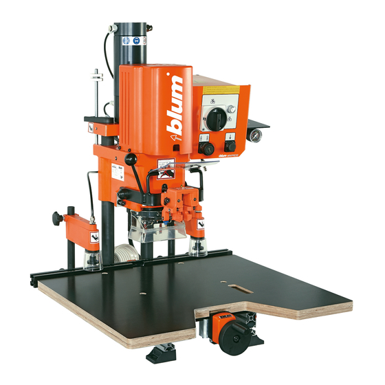
MINIPRESS P boring and insertion machine - OPERATORS' MANUAL
Please keep a copy of the Operators' Manual accessible to machine operators.
Only those individuals who are properly trained and who
have read and understood the Operators' Manual may set
up, operate, or service this machine.
BA-106/1EA M53.10XX
Advertisement
Table of Contents

Related Manuals for BLUM MINIPRESS P


Summary of Contents for BLUM MINIPRESS P
- Page 1 MINIPRESS P boring and insertion machine - OPERATORS’ MANUAL Please keep a copy of the Operators’ Manual accessible to machine operators. Only those individuals who are properly trained and who have read and understood the Operators’ Manual may set up, operate, or service this machine.
- Page 2 BA-106/1EA M53.10XX...
-
Page 3: A - Limited Warranty
Dear valued Blum customer, We would like to congratulate you on your decision to purchase the Blum boring and insertion machine. You are now the owner of a modern, high-quality machine that will give you years of productive use with the proper care and maintenance. -
Page 4: Table Of Contents
B - Table of contents 1. Machine information A - Limited warranty B - Table of contents C - How to use this manual D - Safety information D.1 - Safety decals D.2 - Intended use D.3 - Safety instructions E - Orientation diagram 2 - Machine setup 2.1 - Unpacking and assembly... -
Page 5: C - How To Use This Manual
B - Table of contents 5.1.12) Releasing clamps (optional) 6 - Other installation 6.1 - Boring hole groups 6.1.1) Required parts 6.1.2) Setting drill bit length 6.1.3) Setting boring pattern 6.1.4) Inserting drill bits into the chuck 6.1.5) Checking boring depth setting 6.1.6) Setting stroke speed 6.1.7) Setting boring distance 6.1.7) Setting the ruler stops (2.7) -
Page 6: D - Safety Information
• This machine is designated for commercial and industrial applications and shall be used by fully trained professionals only. The machine is only intended for the boring and insertion of Blum hardware into panels of wood or laminated particle board. The ma- chine should not be used for any other purpose. - Page 7 • After finishing work, disconnect the machine from the power supply. (3.1) • CAUTION: For your own safety, use only those accessories which are recommended or indicated in the manual or Blum sales literature. • Do not make any alterations or modifications to the machine.
-
Page 8: E - Orientation Diagram
E - Orientation diagram 7.10 4.14 4.10 4.23 4.21 4.18 4.20 4.17 4.19 7.10 4.13 2.11 2.12 4.14 4.12 Do not remove! BA-106/1EA M53.10XX... - Page 9 E - Orientation diagram Mounting foot 4.11 Boring depth stop Base ruler 4.12 Safety shield ring Ruler stop 4.13 Stroke speed adjustment Compressed air pressure gauge 4.14 Stroke brake adjustment 2.10 Arrow indicating motor rotation 4.17 Hold down clamp 2.11 Pressure adjustment knob 4.18 Hold down clamp loosening knob...
-
Page 10: Machine Setup
This procedure can also be used to set a stop between two already installed stops. 2.1.5) Attaching work table a) Work table (Blum reference number MZA.5300) • Set work table on runner plate • Attach work table to runner plate... -
Page 11: Connecting To Compressed Air System
2 - Machine setup 2.11 2.2 - Connecting to compressed air system 2.2.1) Connecting air supply ATTENTION: During the following procedure, the boring unit (4.23) makes an upward motion 2.12 • Connect the air supply to the system vent valve (2.12) on the air filter assembly (7.1) -
Page 12: 3) Correcting Motor Rotation
2 - Machine setup 2.3.3) Correcting motor rotation ATTENTION: The electrical connection must be performed by a qualified electrician! If the motor rotation is wrong: • Set drill motor power (3.1) to OFF • Disconnect machine from power supply • Switch L1 and L2 at plug connections •... -
Page 13: Operator Panel
3 - Description of operator panel 3.1 - Description of operator panel 3.1.1) Designation of operating elements • (3.1) Power switch / main disconnect • (3.2) Drill/press stroke button • (3.3) Clamp button • (3.4) Operational status indicator light ATTENTION: The power switch does not disconnect the boring machine from the air pressure system. -
Page 14: Hinge Installation
4 - Hinge installation 4.1 - Concealed hinge installation 4.1.1) Required parts • Bits: 1x ø 35 mm clockwise (4.1) (marked in black) 2x ø 8 mm counterclockwise (4.2) (marked in orange) • Cover caps (4.3) • Insertion ram MZM.00XX (4.4) (see catalogue to determine the proper insertion ram for the respective concealed hinge) -
Page 15: 7) Boring Depth Stop (4.11)
4 - Concealed hinge installation 4.1.7) Boring depth stop (4.11) Another option to maintain a constant boring depth is to install the boring depth stop. When the boring depth stop is installed, the boring depth is always 13 mm regardless of the thickness of the work piece. -
Page 16: 11) Setting The Boring Distance
4 - Concealed hinge installation 4.1.11) Setting the boring distance • Set the desired dimension using the hand wheel • Example: CLP - 23.5 mm Symbols: Line - boring with MZK.1000, 7 spindle boring head METABOX / TANDEMBOX 20,5 COMPACT - hinge 23,5 CLIP - hinge Line - boring... -
Page 17: 15) Setting Clamps (Optional) (4.17) To The Material Thickness
4 - Concealed hinge installation 4.1.15) Setting clamps (optional) (4.17) to the material thickness • Loosen clamping knob (4.18) 4.18 • Set the clamps (4.17) so that the distance between the door and the clamp guard 4.17 (4.19) is a max. x = 1/8” / 3 mm. 4.19 •... -
Page 18: 19) Checking The Tilt Adjustment Of The Swing Arm (4.8)
4 - Concealed hinge installation 4.1.19) Checking the tilt adjustment of the swing arm (4.8) • Swivel down swing arm (4.8) to the stop. • Check whether or not the concealed hinge is aligned with the bored holes. • If it is misaligned, this can be caused by two things: a) Swivel arm (4.8) is not set vertical. -
Page 19: Mounting Plate Installation
5 - Mounting plate installation 5.1 - Wing mounting plate installation 5.1.1) Required parts • Drill bits: 1 x ø5 mm clockwise (5.1) (marked in black) 1 x ø5 mm counterclockwise (5.2) (marked in orange) • Cover caps (4.3) • Cabinet side •... -
Page 20: 9) Placing Cabinet Side On The Work Table And Pushing Up Against The Stop
5 - Mounting plate installation 5.1.9) Placing cabinet side on the work table and pushing up against the stop (See point 4.1.14) 5.1.10) Setting clamps (optional) (4.16) to the material thickness (See point 4.1.15) 5.1.11) Boring (See point 4.1.18) 5.1.12) Releasing clamps (optional) •... -
Page 21: Other Installation
6 - Other installation 6.1 - Boring hole groups 6.1.1) Required parts • Drill bits: 1x ø 5 mm clockwise (6.1) (marked in black) 2x ø 5 mm counterclockwise (6.2) (marked in orange) • Cover caps (4.3) • Cabinet side 6.1.2) Setting drill bit length (See point 4.1.2) 6.1.3) Setting boring pattern... -
Page 22: Maintenance And Service
7 - Maintenance and service 7.1 - Maintenance 7.1.1) Maintenance ATTENTION: Disconnect electrical and pneumatic power from machine before per- forming any maintenance operation. ATTENTION: The cylinder remains pressurized after pnematic power is disconnected from machine. To release cylinder, see section 7.1.4 for cylinder depres- surization instructions. -
Page 23: Troubleshooting
8 - Troubleshooting 8.1 - Error during boring Error Cause Solution Comment Bored holes too large, Drill bit diameter is too large Check drill bit none oval or ragged Drill bits are warped or bent Replace drill bit none Feed rate for boring is too high Adjust brake See point 4.1.8 Boring through work pieces... - Page 24 8 - Troubleshooting Error Cause Solution Comment Boring depth does Boring depth set incorrectly Correct boring depth setting See point 4.1.5 not match setting Drill bit length does not match Drill bit length set to 57 mm See point 4.1.2 Drill bits not completely pushed into the Clean dirt from chuck and completely insert See chapter 4...
-
Page 25: Hardware Insertion Error
8 - Troubleshooting 8.2 - Hardware insertion error Error Cause Solution Comment Hardware cannot be The air pressure is too low Air pressure must be 80-100 psi. See point 2.2.2 inserted or only with great difficulty Insertion ram or swing arm is driving Remove object none against an object (e.g. -
Page 26: Function Errors
8 - Troubleshooting 8.3 - Function errors Error Cause Solution Comment Motor does not run Machine is not connected to the power Connect machine to the power supply none supply Machine is not connected to the air sup- Connect machine to the air supply at least 80 psi Building circuit breaker has failed Reset circuit breaker or replace... - Page 27 8 - Troubleshooting 8.3 - Function errors Error Cause Solution Comment Clamps do not Incorrect clamp button position Change clamp button position See point 3.1.3 function (optional) Clamp valve defective Replace clamp valve none Operational status Indicator lamp bulb defective Replace neon bulb See point 7.1.3 indicator does not...
-
Page 28: User-Supplied Work Table
9 - User-supplied work table / 10-13/16" Ø15 Ø9 All dimensions in millimeters • If you are making your own work table, use plywood or laminated wood. • In addition, please use the supplied screws for attaching the work table. BA-106/1EA M53.10XX... -
Page 29: Diagrams
10 - Diagrams 10.1 - Electrical diagram – 1Φ 220 V 60 Hz black white (optional) green (optional) (optional) 0.33 (optional) 1x220V 60Hz, Note: if K2 is not in use, K1 is wired with 1S2 via S3-60%ED 7.1A, 1.1kW, 3260rpm C 30 F 400VDB W1,W2 ... -
Page 30: Pneumatic Diagram
10 - Diagrams 10.3 - Electrical diagram – 3Φ 460 V 60 Hz schwarz - black weiss - white rot - red 460V grün - green 0,1AT 0,1AT 230V prim: 460V 50/60Hz sek: 230V, 10VA 690V IEC, 600V UL/CSA 4552380 F1,F2 250V, dm5x20mm, 0,1AT 3809200 250V/6A, G1/4"... -
Page 31: Technical Data
• boring only 1-3/4” (45 mm) • Boring distance center spindle: 0 to 2-3/4” (0 to 70 mm) • inserting see BLUM complete catalog 5) Max. boring diameter 6) Accessories • 1-3/8” (35 mm) diameter • For accessories see BLUM complete catalog BA-106/1EA M53.10XX... - Page 32 Blum Inc. Functional Hardware Mfg. For Kitchen Cabinets 7733 Old Plank Rd. Stanley NC 28164 Toll-free: 1-800-438-6788 Tel.: 1-704-827-1345 Fax: 1-704-827-0799 sales.us@blum.com Ident-Nr.: 936.682.0 DokId: BAU0014971422 IDX01 BA-106/1EA M53.10XX...
Need help?
Do you have a question about the MINIPRESS P and is the answer not in the manual?
Questions and answers