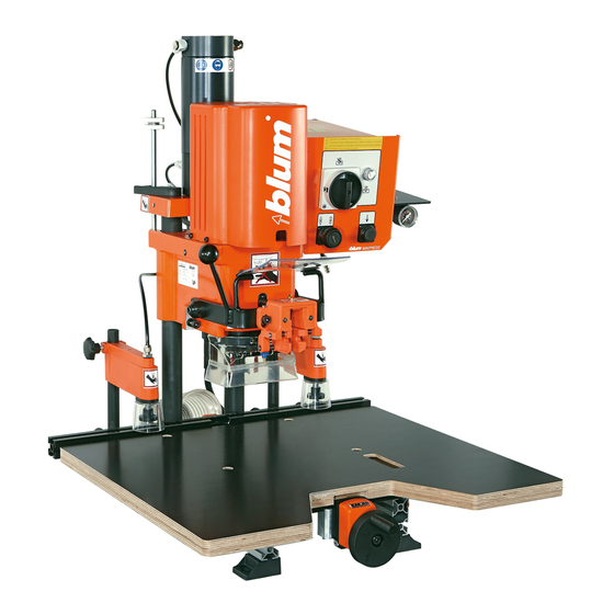
BLUM MINIPRESS P Manual
Hide thumbs
Also See for MINIPRESS P:
- Operator's manual (32 pages) ,
- Safety and instruction manual (64 pages)

Related Manuals for BLUM MINIPRESS P


Summary of Contents for BLUM MINIPRESS P
- Page 1 051140 MINIPRESS P Please keep a copy of the operating instructions. BA-101/3EN M53.XXXX...
-
Page 2: A- Orientation Diagram
A- Orientation diagram 3.10 3.23 3.20 3.21 3.18 3.11 3.17 3.19 3.12 DIN 911 DIN 911 SW 4 SW 6 DIN 911 DIN 911 Safety device: SW 3 SW 4 Do not remove and replace immediately with original parts if damaged. BA-101/3EN M53.XXXX... -
Page 3: Table Of Contents
B - Table of contents A- Orientation diagram B - Table of contents C - Reading guide C.1 - How to use these operating instructions D - Safety information D.1- Remaining risks according to ISO EN 12100-2 D.2 - Safety decals D.3 - Intended use D.4 - Safety information D.5 - Noise emission... - Page 4 B - Table of contents 4.1.9) Placing cabinet side on the work top and pushing up against the stop or marking line 4.1.10) Setting hold down clamps to the material thickness 4.1.11) Drilling 4.1.12) Loosing hold down clamps 5 - Assembly 5.1 - Drilling hole groups 5.1.1) Required parts 5.1.2) Setting drill bit length...
-
Page 5: C - Reading Guide
Dear valued Blum customer, We would like to congratulate you on your decision to purchase the Blum assembly machine. You are now the owner of a modern, high-quality assembly machine that will give you years of productive use with the proper care and maintenance. -
Page 6: D - Safety Information
• The intended purpose of laser module MZR.5300 is measurement and position determination on the work piece in conjunction with MINIPRESS P. Only wood or particle board should be used as the work piece since they are non-reflective. Coated and/or reflective work pieces may not be used. -
Page 7: Noise Emission
(3.1) to POS. 0 after finishing work. • CAUTION: For your own safety, use only those accessories which are recommended or indicated in the manual or Blum sales literature. • Do not make any alterations or modifications to the assembly machine. - Page 8 MINIPRESS P 2010 Ser.No.: JB 00001 kg / Bohr- und Beschlagsetzmaschine Ref.No.: M53.1000 Julius Blum GmbH - A - 6973 BG Пробивни машини Bore- og beslagssætmaskiner Bohr- und Beschlagsetzmaschine Drilling and insertion machine Puurimis- ja sisestusmasinad Asennusporakoneet Machine pour percer et poser des ferrures EL Μηχάνημα διάτρησης και τοποθέτησης...
-
Page 9: F- Ec Declaration Of Conformity / Techn. Data
F.1 - EC Declaration of Conformity Julius Blum GmbH, Industriestr. 1, A-6973 Höchst herewith declare on our own responsibility that the product MINIPRESS (M53. xxxx) with drilling heads (MZK.1000, MZK.1900, MZK.8000, MZK.8800) to which this Declaration refers, complies with the following... -
Page 10: Assembly Machine Setup
1 - Assembly machine setup 1.1 - Unpacking and assembly 1.1.1) Assembly machine space requirement 771 mm 684 mm 690 mm ATTENTION: The centre of gravity for the assembly machine is in the back 1.1.2) Unpacking assembly machine and attaching to a suitable table •... -
Page 11: 4) Attaching Swivel Stops
1 - Assembly machine setup 1.1.4) Attaching swivel stops • Loosen clamping knob until the counter plate protrudes 10 mm • Attach swivel stop to ruler at an angle and stand upright • Tighten clamping knob Note: This procedure can also be used to set a stop between two available stops. -
Page 12: Dust Extraction
• Set main switch (2.1) to Pos.0 • The attached plug should correspond to national standards. Provide a 7 A mains backup fuse (see Chapter 9 - Diagrams). Important: The assembly machine is designed for the voltage printed on the label of the connection cable. -
Page 13: Description Of Operator Panels
2 - Description of operator panels 2.1 - Description of operator panels 2.1.1) Designation of operating elements • (2.1) Main switch • (2.2) Feed switch • (2.3) Hold down clamp switch • (2.4) Operating mode display switch ATTENTION: The main switch does not disconnect the assembly machine from the air pressure system. -
Page 14: Assembly
3 - Assembly 3.1 - Furniture hinge assembly 3.1.1) Required parts • Drill bits: 1x ø 35 mm clockwise (3.1) (marked in black) 2x ø 8 mm counterclockwise (3.2) (marked in red) • Cover caps (3.3) • Insertion ram MZM.00XX (3.4) (see catalogue to determine the proper insertion ram for the respective furniture hinge) -
Page 15: 6) Drilling Depth Stop
3 - Assembly 3.1.6) Drilling depth stop (3.11) Another option to maintain a constant drilling depth is to install the drilling depth stop. When the drilling depth stop is installed, the drilling depth is always 13 mm regardless of the thickness of the work piece. Installing the drilling depth stop: •... -
Page 16: 11) Setting Swivel Stops
3 - Assembly 3.1.11) Setting swivel stops (1.7) Set the swivel stops (1.7) to the desired dimension and clamp. IMPORTANT: Indicator edge is on the inside of the swivel part. 3.1.12) Placing door on the work top and pushing up against the stop or marking line IMPORTANT: The stop surface can be enlarged by swivelling the stop flap forward for... -
Page 17: 15) Clipping Furniture Hinge On To The Insertion Ram
3 - Assembly 3.1.15) Clipping furniture hinge on to the insertion ram 3.1.16) Drilling ATTENTION: All items except for the work piece should be removed from the work area of the assembly machine. Keep your hands out of work area (A). •... -
Page 18: Assembly
4 - Assembly 4.1 - Cruciform mounting plate assembly 4.1.1) Required parts • Drill bits: 4.2 4.1 1 x ø5 mm clockwise (4.1) (marked in black) 1 x ø5 mm counterclockwise (4.2) (marked in red) • Cover caps (3.3) • Cabinet Side •... -
Page 19: 9) Placing Cabinet Side On The Work Top And Pushing Up Against The Stop Or Marking Line
4 - Assembly b) If the bottom edge of the door should be shorter or longer than the bottom edge of the carcase, the stops (1.7) must be set according to the measured difference. In ad- dition, the base ruler (1.2) must also be re-positioned. -
Page 20: Assembly
5 - Assembly 5.1 - Drilling hole groups 5.1.1) Required parts • Drill bits: 1x ø 5 mm clockwise (5.1) (marked in black) 5.2 5.1 5.2 2x ø 5 mm counterclockwise (5.2) (marked in red) • Cover caps (3.3) • Setup gauge (5.3) •... -
Page 21: Maintenance And Service
6 - Maintenance and service 6.1 - Maintenance 6.1.1) Maintenance • Drilling dust should be removed from the assembly machine on a regular basis • Before using the machine, you should always check the air filter unit (6.1) for water which may accumulate there. -
Page 22: Troubleshooting
7 - Troubleshooting 7.1 - Error during drilling Error Cause Solution Comment Drilled holes too Drill diameter is too large Check drill none large, oval or ragged Drills are twisted Replace drill none Cam speed for drilling is too high Set correct cam speed See point 3.1.7 Drilling through work pieces... - Page 23 7 - Troubleshooting 7.1 - Error during drilling Error Cause Solution Comment Assembly machine is driving against an Remove object none object (e.g. swivel stop) Feed switch was released before the Keep feed switch engaged until the drilling none drilling depth was reached depth has been reached Work top height (thickness) Put work top underneath until a height of 24...
- Page 24 7 - Troubleshooting Adjusting the laser angle Only carry out the following steps when the laser angle is not correct • Loosen set screw using allen key (counter-clockwise) • Turn laser diode until the correct angle is reached on the work piece or ruler.
-
Page 25: Fitting Insertion Error
7 - Troubleshooting 7.2 - Fitting insertion error Error Cause Solution Comment Fittings cannot be The air pressure is too low Air pressure must be 5 - 7 bars. See point 1.2.2 inserted or only with great difficulty Insertion ram or swing arm is driving Remove object none against an object (e.g. - Page 26 7 - Troubleshooting 7.3 - Function errors Error Cause Solution Comment Motor overheats Assembly machine connected to the Check mains voltage and compare with See electrical dia- wrong voltage motor data. Have checked by authorised gram electrician Drilling in hard wood with too high a Reduce cam speed See point 3.1.7 speed...
-
Page 27: Appendix
8 - Appendix 8.1 – User-supplied work top Ø15 Ø9 • If you are making your own work table, use plywood or laminated wood. • In addition, please use the supplied screws for fixing the work table. BA-101/3EN M53.XXXX... -
Page 28: Diagrams
9 - Diagrams 9.1 - Electrical diagram 1x 230 V 50 Hz BA-101/3EN M53.XXXX... -
Page 29: Electrical Diagram 3X 230 V 50 Hz
9 - Diagrams 9.2 - Electrical diagram 3x 230 V 50 Hz BA-101/3EN M53.XXXX... -
Page 30: Electrical Diagram 3X 400 V 50 Hz
9 - Diagrams 9.3 - Electrical diagram 3x 400 V 50 Hz BA-101/3EN M53.XXXX... -
Page 31: Pneumatic Diagram
9 - Diagrams 9.4 - Pneumatic diagram BA-101/3EN M53.XXXX...
Need help?
Do you have a question about the MINIPRESS P and is the answer not in the manual?
Questions and answers