
Related Manuals for BLUM MINIPRESS PRO


Summary of Contents for BLUM MINIPRESS PRO
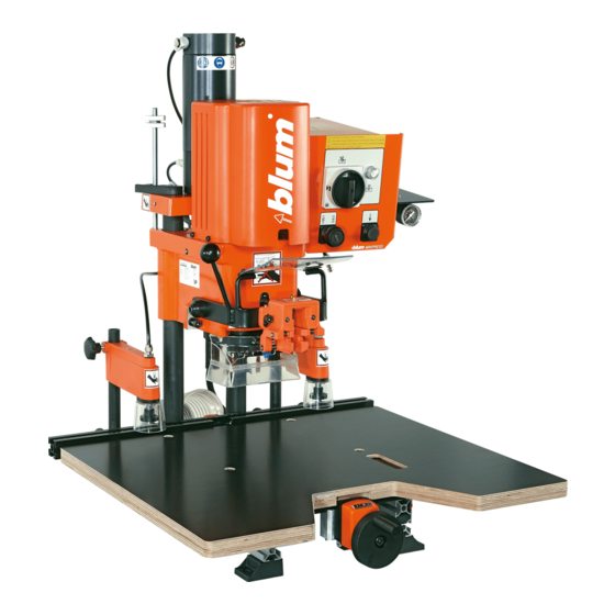
- Page 1 051140 MINIPRESS PRO Please keep a copy of the operating instructions. The operating instructions contain the EC Declaration of Conformity, which must be produced for authorities upon request. BA-102/2EN M54.XXXX...
-
Page 2: A- Orientation Diagram
A- Orientation diagram 1.10 4x M30.020-09 4x DIN912 M8x30 DIN 895 SW 10/13 metric DIN 911C hex key metric 6 DIN 911C hex key metric 4 DIN 911C DIN 911C hex key metric 2.5 hex key metric 2 T-handle hex wrench 4x150 metric DIN 911 Safety device: Do not remove - replace immediately with original parts if damaged. -
Page 3: Table Of Contents
B - Table of contents A- Orientation diagram B - Table of contents C - Reading guide C.1 - How to use these operating instructions D - Safety information D.1- Remaining risks according to ISO EN 12100-2 D.2 - Safety decals D.3 - Intended use D.4 - Safety information D.5 - Noise emission... - Page 4 B - Table of contents 4.1 - Pre-setting revolver for drilling depth 5 - Working with the assembly machine 5.1 - Creating a setup plan 5.1.1) Identifying drilling head and ruler 5.1.2) Removing setup plan template 5.1.3) Creating work piece drawings on the setup plan 5.1.4) Drilling head setup for machine 5.1.5) Setting drilling depth 5.1.6) Setting work top...
-
Page 5: C - Reading Guide
Dear valued Blum customer, We would like to congratulate you on your decision to purchase the Blum assembly machine. You are now the owner of a modern, high-quality assembly machine that will give you years of productive use with the proper care and maintenance. -
Page 6: D - Safety Information
D - Safety information D.1- Remaining risks according to ISO EN 12100-2 • This machine complies with current safety standards. However, risks remain for • the operator and second persons due to the stroke movement of the drilling unit and especially in case safety devices are removed or control elements should fail. • Other remaining risks are indicated by the safety decals and in the following safety rules. It is therefore absolutely necessary to fol- low all safety instructions carefully. D.2 - Safety decals Completely read the operating instructions and the safety information before operating the assembly machine Wear proper eye and face protection when operating this machine Wear proper ear protection when operating this machine Only one person at a time must operate the machine. -
Page 7: Safety Information
• Only use sharp, clean drill bits. Attach drill bits securely. • Particular care must be taken when working on sections that jut out over the work top. Attach a larger work table or use extensions. • Secure the work piece during drilling/insertion. Use the assembly machine clamps or if these are not sufficient for the particular job, use suitable clamping equipment. • Wear appropriate work clothing. • You should always check that all safety devices and machine parts are functioning properly before use. Replace damaged parts with original Blum parts. • Make sure that no other tools or objects are on the work table aside from your work piece before turning on the assembly machine. • Always turn the main switch (2.1) to POS. 0 • For your own safety, only use those accessories which are recommended or indicated in the instruction leaflet or the BLUM catalogue. • Do not make any alterations or modifications to the assembly machine. - Page 8 MINIPRESS PRO 2010 Ser.No.: KC00001 kg / Bohr- und Beschlagsetzmaschine Ref.No.: M54.2000 Julius Blum GmbH - A - 6973 BG Пробивни машини Bore- og beslagssætmaskiner Bohr- und Beschlagsetzmaschine Drilling and insertion machine Puurimis- ja sisestusmasinad Asennusporakoneet Machine pour percer et poser des ferrures EL Μηχάνημα διάτρησης και τοποθέτησης...
-
Page 9: E - Serial Tag
F - EC Declaration of Conformity / Techn. Data F.1 - EC Declaration of Conformity Julius Blum GmbH, Industriestr. 1, A-6973 Höchst herewith declare on our own responsibility that the product MINIPRESS (M54.xxxx) with drilling heads (MZK.2000, MZK.2100, MZK.2110, MZK.2200, MZK.2230, MZK.2400, MZK.2410, MZK.2800, MZK.2810) to which this Declaration refers, complies with the following EC Directives:... -
Page 10: Assembly Machine Setup
1 - Assembly machine setup 1.1 - Unpacking and assembly 1.1.1) Assembly machine space requirement 863 mm 936 mm 875 mm ATTENTION: The centre of gravity for the assembly machine is in the back 1.1.2) Space requirement of drilling head and ruler storage rack (optional) Part number: MZA.2600 613 mm 600 mm... -
Page 11: 6) Removing Ring Screw (2.6)
1 - Assembly machine setup 1.1.6) Removing ring screw (1.6) Note: Remove the ring screws (1.6) to avoid damaging the assembly machine and work piece. 1.1.7) Attaching table (1.7) • Attach table (1.7) using screws provided 1.11 1.1.8) Attaching handle • Insert gauge-glass (1.5) •... -
Page 12: Electrical Connection
1 - Assembly machine setup 1.3 - Electrical connection mwttttt mmmmtm tmttt ttt tmttttttmt mttt mwttttt mmm mwttttt mwttttt mmhb nhnhn hhnh nmmtm tmttt ttt tmtttlkl kll lkkltttmt mttt 1.3.1) Electrical connection mwttttt mmm mwtt tttmmhb nhnhn hhnh nmmtm tmttt ttt tmtttlkl kll lkkltttmt mttt mwttttt mmm mwttttt mmhb nhnhn hhnh nmmtm tmttt ttt tmtttlkl kll lkkltttmt mttt mwttt ttmmm... -
Page 13: Dust Extraction
1 - Assembly machine setup 1.4 - Dust extraction 1.4.1) Connecting extraction system to the assembly machine ATTENTION: The machine must be connected to a dust extraction system! • Insert the spiral hose with an inside diameter of 50 mm into the receiving tube (1.4) and fix it • Make sure that the average air velocity for the extraction system is at least 20 m/sec. • If there is no extraction system connector with a diameter of 50 mm, the supplied adapter (image 1.4.2) can be used. -
Page 14: Description Of Operator Panel
2 - Description of operator panel 2.1 - Description of operator panel 2.1.1) Designation of operating elements • (2.1) Main switch • (2.2) Feed switch • (2.3) Hold down clamp switch • (2.4) Operating mode display indicator ATTENTION: The main switch (2.1) does not disconnect the assembly machine from the air pressure system. -
Page 15: How To Operate The Machine
3 - How to operate the machine 3.1 - Vertical drilling unit 3.1.1) Gearbox replacement • Main switch (2.1) at Pos. 0 • Loosen locking device (3.1) by turning to the left • Lift the locking unit on the locking device (3.1) and pull forward • Remove the drilling head from the guide and place to the side • Insert the desired drilling head into the guide until the stop ATTENTION: A damaged coupling could cause injury. Tighten locking device before operating the machine Move the locking unit on the locking device (3.1) -
Page 16: Setting Work Top To Drilling Distance
3 - How to operate the machine 3.2 - Setting work top to drilling distance 3.2.1) Setting drilling distance • Loosen clamping (1.0) • Set the desired dimension using the hand wheel (1.1) • Tighten clamping (1.0) 3.3 - Setting clamps 3.3.1) Setting hold down clamps (3.3) to the material thickness • Open clamp screw •... -
Page 17: 3) Setting Cam Brake (4.7)
3 - How to operate the machine 3.5.3) Setting cam brake (3.7) The brake is set by turning the screw (3.7) on the cylinder. • Turn screw (3.7) to the right: slows down the drill bit • Turn screw (3.7) to the left: speeds up the drill bit 3.6 - Setting operating mode ATTENTION: Set main switch... -
Page 18: 2) Clipping Fitting Onto Insertion Ram (4.7)
3 - How to operate the machine 3.7.2) Clipping fitting onto insertion ram (3.7) 3.7.3) Pushing work piece to the swivel stop (8.1) Important: The stop surface can be enlarged by swivelling the stop flap forward for grooved work pieces and work pieces with radiuses. 3.7.4) Pushing work piece to the marking line 3.7.5) Drilling ATTENTION:... -
Page 19: Drilling Depth Setup Explanation
4 - Drilling depth setup explanation 4.1 - Pre-setting revolver for drilling depth The drilling depths for panel thicknesses 16 and 19 mm are already pre-set. 2 additional dimensions can also be pre-set. • Lift revolving handle (3.4) The revolver is located on the back of the machine. • Remove revolver Two screws are preset to 16 and 19 mm. -
Page 20: Working With The Assembly Machine
5 - Working with the assembly machine 5.1 - Creating a setup plan 5.1.1) Identifying drilling head and ruler Note: To better understand the following description and procedures, take a look at the included sample setup plan. • In the overview on pages xx, xx and xx, select the required gear box and ruler (8.2) for the desired assembly application. 5.1.2) Removing setup plan template • Fill out header data Explanation of symbols:... -
Page 21: 5) Setting Drilling Depth
Set the swivel stop (8.1) to the ruler (8.2) and label with coloured stickers. (The corresponding stickers are provided with MINIPRESS PRO) • Add ruler type and description to the setup plan. • Enter the dimensions on the ruler over the stops to which the stops are set. • Stop installation is described in chapter 8 5.1.8) Storing setup plan Put the completed setup plan into the clear plastic folder and store on the setup plan rack (5.1) -
Page 22: Assembly Overview
6 - Assembly Overview 6.1 - Assembly with drilling heads and rulers Assembly application Drilling heads* Rulers* MPH MPV SY-H SY-V Furniture hinges Dowel plates Cruciform mount- ing plates Cabinet profiles System drilling Furniture connec- tors Furniture connec- tors TANDEMBOX + METABOX Front fixings preferred use... -
Page 23: Drilling Heads
7 - drilling heads 7.1 - General 7.1.1) Attaching drilling heads • Attach drilling head holder to a wall, table or the storage rack. The storage rack is available from Blum as an accessory. (MZA.2600) 7.1.2) Setting drill bit length IMPORTANT: The total length of the drill bits (from bit-tip to adjustment screw) should be x = 57 mm. -
Page 24: Drilling Heads
7 - drilling heads 7.2 - drilling heads 7.2.1) FH drilling head: MZK.2000 Furniture hinge drilling head for standard hinges Ø35 Ø8 Ø8 • Drilling head with 3 spindles • With drilling depth spacing • Swing arm for ram attachment 22,5 22,5 • Drill bits: (A) ... 2x Ø 8 mm left hand / (B) ... 1x Ø 35 mm right hand • Colour coded bits: left hand are red, right hand are black 7.2.2) MPH drilling and insertion head: MZK.2100... -
Page 25: 4) Syh Drilling Head: Mzk.2200.01
7 - drilling heads 7.2.4) SYH drilling head: MZK.2200.01 for all Blum cabinet profiles • Drilling head with 8 spindles • Drill bits: (A) ... 4x Ø 5 mm left hand (B) ... 4x Ø 5 mm right hand • Colour coded bits: left hand = red right hand = black Ø5 Ø5... -
Page 26: Rulers
- Installing ruler holders to the work top: • Attach a ruler holder to the work top surface. • Attach the second ruler holder to the floor • Place the ruler vertically into the lower holder and clip into the top holder. The storage rack can also be used as a ruler holder. The storage rack (MZA.2600) is available from Blum as an accessory. 8.1.2) Attaching swivel stop (8.1) • Loosen clamping knob until the counter plate protrudes 10 mm • Attach swivel stop to ruler at an angle and stand upright • Tighten clamping knob... -
Page 27: 3) Ld Ruler: Mzl.2080 Line Drilling Ruler
8.2.5) Ruler supports: MZV.2100 for extension ruler • Attach the ruler supports to the table at the outside third of the extension ruler. Important: Make sure that the calibration on the ruler support corresponds to the one on the work top of the MINIPRESS PRO. Pay attention to the adjust- ment area of the work top. • Before setting the work top, loosen the clamping lever on the ruler support. Then retighten. -
Page 28: Maintenance And Service
Reattach front (6.7) to the operating mode display indicator. 9.1.3) Replacing a damaged gearbox coupling ATTENTION: Replace broken or damaged parts immediately. Only use Blum original parts. • Use a flathead screwdriver to remove the damaged coupling (9.1). • Slip the replacement coupling (9.1) onto the shaft until it aligns with the shaft at the top. -
Page 29: Troubleshooting
11 - Troubleshooting 11.1 - Error during drilling Error Cause Solution Comment Drilled holes too Drill diameter is too large Check drill none large, oval or ragged Drills are twisted Replace drill none Cam speed for drilling is too high Set correct cam speed See point 3.5.1 Drilling through work pieces... - Page 30 11 - Troubleshooting 11.1 - Error during drilling Error Cause Solution Comment Assembly machine is driving against an Remove object none object (e.g. swivel stop) Feed switch was released before the Keep feed switch engaged until the drilling none drilling depth was reached depth has been reached Work top height (thickness) Put work top underneath until a height of 24...
- Page 31 11 - Troubleshooting Adjusting the laser angle Only carry out the following steps when the laser angle is not correct • Loosen set screw using allen key (counter-clockwise) • Turn laser diode until the correct angle is reached on the work piece or ruler. Use a work piece for the alignment. Affix the work piece to the work center using clamps. • Re-tighten set screw using allen key (clockwise) Laser beam is not perpendicular Only carry out the following steps when the laser is not perpen-...
-
Page 32: Fitting Insertion Error
11 - Troubleshooting 11.2 - Fitting insertion error Error Cause Solution Comment Fittings cannot be The air pressure is too low Air pressure must be 5 - 7 bars. See point 1.2.2 inserted or only with great difficulty Insertion ram or swing arm is driving Remove object none against an object (e.g. - Page 33 11 - Troubleshooting Error Cause Solution Comment Assembly machine connected to the Check mains voltage and compare with See chapter 12 wrong voltage motor data. Have checked by authorised - Diagrams electrician Motor defective Have motor replaced by an authorised none electrician Motor overheats...
-
Page 34: Appendix
11 - Appendix 11.1 – User-supplied work top Ø 15 Ø 9 A (1:2) (180,8) 277,5 176,5 B (1:2) • If you are making your own work table, use plywood or laminated wood. • In addition, please use the supplied screws for fixing the work table as well as spacer discs M54.220-12. • Gauge-glass M54.220-14 should be installed after table assembly. BA-102/2EN M54.XXXX... -
Page 35: Diagrams
12 - Diagrams 12.1 - Electrical diagram1x 230 V 50 Hz braun - brown blau - blue gelb/grün - yellow/green T1,6A 1x230V 50Hz, S6-60%ED 5,0A, 1,1kW, 2830/min File: MP EA 1x230V mit Zeitrelais.FH9 C 25µF 400VDB 12.2 - Electrical diagram 3x 220 V 60 Hz schwarz - black weiss - white rot - red... -
Page 36: Electrical Diagram 3X 230 V 50 Hz
12 - Diagrams 12.3 - Electrical diagram 3x 230 V 50 Hz schwarz - black blau - blue braun - brown gelb/grün - yellow/green T1,6A T1,6A U 1 V 1 W 1 3x230V W 2 U 2 V 2 3x230V 50/60Hz 4,75A, 1,1kW, File: MP EA 3x230V mit Zeitrelais.FH9 2820 Upm... -
Page 37: Pneumatic Diagram
12 - Diagrams 12.5 - Pneumatic diagram ø8/6 ø80x110 ø25x25 1-10 bar / 3 bar ø6/4 ø6/4 0-10 bar p= 6 bar = 5 bar / p = 7 bar) ø8/6 Gr.3 0474060 G1/8", 5µm 3975560 G1/8", DM40, 0-10 4398790 G1/8"... -
Page 38: Notes
Notes BA-102/2EN M54.XXXX... - Page 39 Notes BA-102/2EN M54.XXXX...
- Page 40 Julius Blum GmbH Beschlägefabrik 6973 Höchst, Austria Tel.: +43 5578 705-0 Fax: +43 5578 705-44 E-Mail: info@blum.com www.blum.com...
Need help?
Do you have a question about the MINIPRESS PRO and is the answer not in the manual?
Questions and answers