
Subscribe to Our Youtube Channel
Related Manuals for BLUM MINIPRESS


Summary of Contents for BLUM MINIPRESS
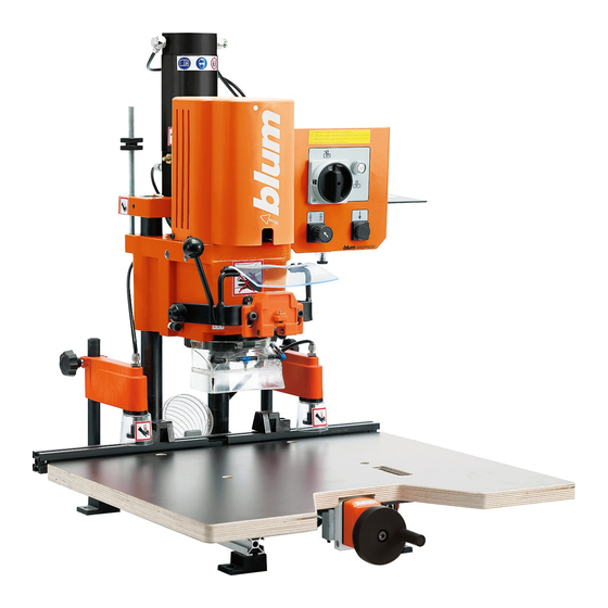
- Page 1 Blum MINIPRESS The machine shall only be used by trained personnel who have completely read and understand the manual. BAU0004823171 IDX00...
- Page 2 PERSONNEL WHO HAVE COMPLETELY READ AND UNDERSTAND THE MANUAL. CONTENTS Page: How to use this manual Safety instructions Designation of parts Initial set-up of MINIPRESS áUnpacking and assembly áConnection to compressed air system á Electrical connection áDust extraction Description of operating panel Hinge insertion process áDrilling of hinge pattern...
- Page 3 How to use the manual How to use this manual 1. Understanding this manual 2. Symbols and their descriptions: Indicates important safety • THE MACHINE rules which must be followed! SHOULD ONLY BE USED BY TRAINED Indicates an important PERSONNEL WHO comment.
- Page 4 Safety instructions Safety instructions Read before operation • Failure to properly follow all safety rules and procedures in this manual, and all warnings and instructions on the machine, may result in serious personal injury or property damage. Safety decal description •...
- Page 5 The machine is only intended for the drilling and insertion of Blum • Observe the location of the control hardware into panels of wood, switches and become familiar with particle board, or laminated particle their operation.
- Page 6 • CAUTION: For your own safety, use only those accessories which are recommended or indicated in the manual or Blum sales literature. • All accessories and attachments must be installed as described in the manual to assure a proper and safe operation of the machine.
- Page 7 Designation of parts Designation of parts D1 ... machine base F15 ... clamping lever D2 ... base ruler F16 ... fixing pin D3 ... clamping lever F17 ... hold-down clamp F18 ... locking screw D4 ... fencing system D5 ... fixing pins for ruler F19 ...
- Page 8 Designation of parts %$0,1,35(66)$,G1US...
- Page 9 Designation of parts Designation of parts D7 ... swivel stop D13 ... box support F3 ... cover caps F5 ... fixing pin for drill head F6 ... lever (to rotate gearbox) F7 ... symbol furniture hinge F11 ... drilling depth stop F12 ...
- Page 10 Designation of parts %$0,1,35(66)$,G1US...
- Page 11 82 lbs (37 kg) so make sure that the table is sturdy enough! • Fit M8 bolts through the drill holes (D1) and tighten them. • Do not install MINIPRESS in a damp area but in a dry room. %$0,1,35(66)$,G1US...
- Page 12 Initial set-up of MINIPRESS 3. Installation of base ruler (D2) 4. Mounting the swivel stops (D7) • Loosen both clamping levers (D3) • Loosen the locking bolt until the T- on the fencing System. nut projects by 3/8“ (10 mm).
- Page 13 Initial set-up of MINIPRESS 5. Assembling the worktable 6. Mounting the box Support (D13) a) Accessory worktable MZA.1000 • Use glue to attach the Box Support (D13) to the rear end of the control • Set the fencing System (D4) to box (surface must be dry and oil- position DP.
- Page 14 Initial set-up of MINIPRESS Connection to compressed air system 1. Connection of air supply 2. Setting the working pressure • The working pressure is 6 bar Warning: (80 - 100 psi). If the machine is operated either below or above the...
- Page 15 Initial set-up of MINIPRESS Electrical connection Dust extraction mwttttt mmmmtm tmttt ttt tmttttttmt mttt mwttttt mmm mwttttt mwttttt mmhb nhnhn hhnh nmmtm tmttt ttt tmtttlkl kll lkkltttmt mttt mwttttt mmm mwtt tttmmhb nhnhn hhnh nmmtm tmttt ttt tmtttlkl kll lkkltttmt mttt...
- Page 16 Desciption of operating panel Description of operating panel set up set up drill/press drill/press drill/press Auto off drill/press Auto off stroke stroke 2. Designation of operating 3. Main switch (E1) elements • (E1) ... main switch Warning: • (E2) ... press drill / press stroke The main switch does not button disengage the machine...
- Page 17 Description of operating panel set up drill/press drill/press Auto off stroke 5. Drill / press stroke button (E2) Warning: Keep your hands out of Warning: working area (A) of the machine when performing Keep your hands away from the tasks below! the working area (A) of the machine when pressing the drill / press stroke button.
- Page 18 Desciption of operating panel set up drill/press drill/press Auto off stroke 5. Hold-down switch (E3) Pos. Hold-down clamps on Pressing the drill / press Auto off stroke button (E2) causes the hold-down clamps to extend automatically. Pos. Hold-down clamps off Auto off The clamps remain retracted if you press the drill / press...
- Page 19 (F2) (marked orange). • To correct drill-bit length, adjust screw accordingly. • Two cover caps (F3) • Insertion ram MZM.XXXX (F4). Important: See Blum catalog for correct ram. All drill bits shall be the same • Door panel length! • Hinge %$0,1,35(66)$,G1US...
- Page 20 Drilling of hinge pattern 3. Select drill pattern 4. Install drill bits • Pull out fixing pin (F5) on drill • Before installing drill bits, always head. disconnect the machine from it’s electrical source (unplugged). • At the same time, move lever (F6) to symbol for hinge drilling pattern •...
- Page 21 Drilling of hinge pattern 5. Check drilling depth adjustment 6. Correcting drilling depth adjustment • Always place operation mode switch to set up position and disconnect the • If the Cutting edges do not touch the machine from it’s electrical source door panel top, correct adjustment.
- Page 22 Drilling of hinge pattern 7. Drilling depth stop (F11) 8. Adjusting the stroke speed Alternatively, drilling depth stops can be Adjustment of the stroke speed is made mounted to ensure a constant drilling by means of the knurled screw (F13) at depth.
- Page 23 Drilling of hinge pattern 9. Checking the pneumatic brake 10. Adjusting the pneumatic brake The pneumatic brake causes the drill To adjust the pneumatic brake, use the head to slow down just before the drill screw (F14) on the left side of the bits penetrate the wood.
- Page 24 Drilling of hinge pattern Pos. Pos. Pos. 11. Fencing System (D4) adjustments 12. Fixed positions of the stop system • Always place operation mode switch • Always place operation mode switch to set up position and disconnect the to set up position and disconnect the machine from it’s electrical source machine from it’s electrical source (unplugged) before performing any...
- Page 25 Drilling of hinge pattern 13. Setting the swivel stops (D7) 14. Place the door on the worktable and slide it until positioned • Always place operation mode at the stop. switch to set up position and disconnect the machine from it’s electrical source (unplugged) before performing any work on the drill Note:...
- Page 26 Drilling of hinge pattern 15. Adjust hold down clamps (F17) • Loosen clamp screw (F18). • Position clamp over panel surface. • Position clamp over panel surface, no more than 6 mm (1/4"). • Tighten clamp screws (F18). %$0,1,35(66)$,G1US...
- Page 27 Hinge insertion Hinge insertion 16. Mount insertion ram onto swing 17. Attaching the hinge on to the arm (F8) in upright position ram. • Place ram over fixing bolts (F20) on swing arm (F8) and tighten. • Make sure that ram adjustment screws sit on fixing bolt.
- Page 28 Hinge insertion 18. Drilling 19. Check alignment of swing arm (F8) WARNING! To avoid serious injury, all • Move Swing Arm (F8) down to stop items must be removed from the working area of the • Make sure the hinge is aligned with machine, except the the drilled hole.
- Page 29 Hinge insertion 19. Hinge insertion WARNING! To avoid serious injury stay clear of drilling area and all pinch points (zone A) except the workpiece. • When inserting hinge, keep one hand on the drill / press stroke button (E2) and the other hand on the swing arm (F8) or on the edge of the door nearest you until the hinge is totally pressed in (outside...
- Page 30 Installation of wing mounting plates Installation of wing mounting plates with system screws 1. Necessary parts 3. Change drill pattern • Drill bits: • Pull out fixing pin (F5) on drill head. - one 5 mm dia. rotating clock wise (G1) (marked black) •...
- Page 31 Installation of wing mounting plates 16mm 7. Setting the fencing system (D4) 8. Setting the swivel stops (D7) • Always place operation mode switch • Always place operation mode switch to set up position and disconnect the to set up position and disconnect the machine from it’s electrical source machine from it’s electrical source (unplugged) before performing any...
- Page 32 Installation of wing mounting plates b) If the lower edge of the door is to be 9. Place the cabinet side on the longer or shorter than the lower worktable and slide it to the stop edge of the cabinet, the stops (D7) (see section F - point 14) must be adjusted accordingly by the difference in dimension.
- Page 33 Drilling of line patterns Drilling of line patterns 1. Necessary parts 3. Change drill pattern • Drill bits: • Pull out fixing pin (F5) on drill head. one 5 mm dia. rotating clockwise (H1) (marked black) • At the same time, move lever (F6) two 5 mm dia.
- Page 34 Drilling of line patterns 7. Adjust fencing system (D4) 8. Adjust positioning stops (D7) (see section F - point 13) • Always place operation mode switch to set up position and 9. Line boring disconnect the machine from it’s electrical source (unplugged) before •...
- Page 35 Drilling of line patterns 10. Slide cabinet side panel against the fence until positioned at the stop (see section F- point 14) 11. Adjust hold down clamps (F17) (see section F - point 15) 12. Drilling (see section F - point 18) 13.
- Page 36 Service and maintenance Maintenance 1. Maintenance • During all maintenance operations, • The guide elements (J2) must be disconnect the machine from it’s cleaned regularly with a dry cloth to electrical source (unplugged). remove dust. (Do not use cleaners Re-connect only for testing. or solvents) •...
- Page 37 Replace defective or damaged parts • Remove the damping ring (J5). immediately! Use only original BLUM parts for • Remove the old clutch (J6). replacement! • Mount the new clutch (J6) on the • Set main switch to set up position.
- Page 38 Service and maintenance 3. Replacing the operation indicator lamp • Disconnect the machine from the electrical supply. • Set the main switch to set up position. • Remove the lamp cover (J7) by releasing the screw. • Remove the defective lamp (J8). (Push and turn counter-clockwise).
- Page 39 Troubleshooting - What to do, if ...? Fault during drilling Fault Cause of fault Eliminating fault Remarks • Drilling depth is not • Setting of depth • Check setting of the See chapter F reached adjustment bolt is depth adjustment F-10 wrong bolt...
- Page 40 Troubleshooting - What to do, if ...? Fault during drilling Fault Cause of fault Eliminating fault Remarks • Pneumatic brake is • Slightly open the See chapter F set too tight throttle valve • Drilled holes are • The fence stops are •...
- Page 41 Troubleshooting - What to do, if ...? Fault during drilling Fault Cause of fault Eliminating fault Remarks • Drilled holes too • Drill bit diameter too • Check drill bit No comments large, oval or large diameter ragged • Drill bit is bent •...
- Page 42 Troubleshooting - What to do, if ...? Fault during drilling Fault Cause of fault Eliminating fault Remarks • Drill bits are dull • Replace or No comments resharpen drill bits • Wrong motor rotation • Correct the motor See chapter rotation •...
- Page 43 Troubleshooting - What to do, if ...? Fault during Hinge insertion Fault Cause of fault Eliminating fault Remarks • Hinges or fittings • Air pressure is not • Adjust air pressure No comments cannot be inserted sufficient to 6 bar (80-100 psi) at all, or can only be inserted with •...
- Page 44 No comments been thrown or fuse fuse has expired • Fuse under the • Repair by authorized See electrical control panel has electrician or Blum schematic expired repair center • Switch not on • Main switch on See section E Pos.1 •...
- Page 45 Troubleshooting - What to do, if ...? Functional fault Fault Cause of fault Eliminating fault Remarks • Motor overheats • Motor connected to • Check main voltage See electrical wrong voltage and compare with schematic motor data. If voltage is wrong, replace machine •...
- Page 46 Troubleshooting - What to do, if ...? Functional fault Fault Cause of fault Eliminating fault Remarks • Drill / press stroke • Repair by Blum No comments valve defect repair center • Cylinder defect • Repair by Blum No comments repair center •...
- Page 47 Appendix Do-it-yourself-worktable 198.5 198.5 Detail X • Use plywood or laminated wood for the worktable! • Use M8 bolts with nuts and washers to secure the worktable, or order the Blum mounting set MZA.1002. %$0,1,35(66)$,G1US...
- Page 48 Any damages under this warranty shall be limited to a maximium of the purchase price of the machine. Should any defect be found in the machine, please submit to Blum, in writing, the reference number, the serial number, and the name of the distributor from whom the machine was purchased.
- Page 49 Provide a 16 A backup fuse diameter 1-3/8“ (35 mm) breaker. 6. Accessories 2. Weight and measurements • For accessories see BLUM catalog • Weight: m = 81 lbs (37 kg) • Dimensions: H = 27-15/16" (710 mm) W = 24" (610 mm) D = 29-15/16"...
- Page 50 Appendix %$0,1,35(66)$,G1US...
- Page 51 Appendix %$0,1,35(66)$,G1US...
- Page 52 Appendix %$0,1,35(66)$,G1US...
- Page 53 Appendix Subject to change without notice! IDNR: 598.608.0 BA63.02 EN-US / 08.06 BAU0004822774 IDX:01 Printed in Austria %$0,1,35(66)$,G1US...
- Page 54 MINIPRESS MP FA 3x460V 60Hz SCHALTSCHEMA / CIRCUIT DIAGRAM SCHÉMA ÉLECTRIQUE / ESQUEMA DE CONEXIONES SCHEMA ELETTRICO / KYTKENTÄKAAVIO File: Schema MP FA 3x460V CSA.p65 schwarz - black weiss - white rot - red 460V grün - green 0,1AT 0,1AT...
- Page 55 MINIPRESS MP FA 3x460V 60Hz PNEUMATIKSCHEMA / PNEUMATIC DIAGRAM SCHÉMA PNEUMATIQUE / ESQUEMA DEL CIRCUITO NEUMATICO File: Schema MP FA 3x460V CSA.p65 SCHEMA PNEUATICO / PAINEILMAKAAVIO ø8/6 ø80x105 ø25x25 1-10 bar / 3 bar ø6/4 ø6/4 0-10bar p = 6bar...
- Page 56 SCHALTSCHEMA / CIRCUIT DIAGRAM MINIPRESS MP FA 3x220V SCHÉMA ÉLECTRIQUE / ESQUEMA DE CONEXIONES SCHEMA ELETTRICO / KYTKENTÄKAAVIO File: Schema MP FA 3x220V CSA.p65 schwarz - black weiss - white rot - red grün - green T1,6A T1,6A U 1 V 1...
- Page 57 MINIPRESS MP FA 3x220V PNEUMATIKSCHEMA / PNEUMATIC DIAGRAM SCHÉMA PNEUMATIQUE / ESQUEMA DEL CIRCUITO NEUMATICO SCHEMA PNEUATICO / PAINEILMAKAAVIO File: Schema MP FA 3x220V CSA.p65 ø8/6 ø80x105 ø25x25 1-10 bar / 3 bar ø6/4 ø6/4 0-10bar p = 6bar = 5bar/p = 7bar) ø8/6...
- Page 58 SCHALTSCHEMA / CIRCUIT DIAGRAM MINIPRESS MP FA 1x220V SCHÉMA ÉLECTRIQUE / ESQUEMA DE CONEXIONES SCHEMA ELETTRICO / KYTKENTÄKAAVIO File: Schema MP FA 1x220V CSA-ATB.p65 black white green T1,6A 1x220V 60Hz, S6-60% 6,5A, 1,48HP, 3420RPM File: MP FA 1x220V-ATB.FH9 C 25µF 400VDB...
- Page 59 MINIPRESS MP FA 1x220V PNEUMATIKSCHEMA / PNEUMATIC DIAGRAM SCHÉMA PNEUMATIQUE / ESQUEMA DEL CIRCUITO NEUMATICO SCHEMA PNEUATICO / PAINEILMAKAAVIO File: Schema MP FA 1x220V CSA-ATB.p65 ø8/6 ø80x105 ø25x25 1-10 bar / 3 bar ø6/4 ø6/4 0-10bar p = 6bar = 5bar/p = 7bar) ø8/6...
- Page 60 Blum, Inc. 7733 Old Plank Rd. Stanley, NC 28164 toll free 800-438-6788 local 704-827-1345 fax 704-827-0799 internet www.blum.us Subject to change without notice! IDNR: 598.594.0 BA63.01 EN-US / 12.03 BAU0004823171 IDX:00 Printed in Austria...
Need help?
Do you have a question about the MINIPRESS and is the answer not in the manual?
Questions and answers