Table of Contents
Advertisement
Quick Links
Advertisement
Table of Contents

Related Manuals for Agilent Technologies HS-16


Summary of Contents for Agilent Technologies HS-16
- Page 1 HS-16 - HS-20 - HS-32 - NHS-35 High Throughput Diffusion Pumps User Manual...
- Page 2 Agilent disclaims all © Agilent Technologies, Inc. 2021 not correctly performed or adhered to, warranties, either express or implied, could result in damage to the product...
-
Page 3: Table Of Contents
Contents Contents About this manual Validity Definitions and terminology Definition of Caution, Warning and Note Warning Symbols Safety Proper use Improper use Disposal Service Diffusion Pump Hazards Explosion Pressurization Hazards Dangerous Substances High Temperatures High Voltages Large Equipment and Heavy Weights Diffusion Pump Description Pump Operation Technical Specifications... - Page 4 Contents Unpacking Setup Assembly Cleaning a New Pump Cleaning Safety Disassembly for Initial Cleaning Reassembly After Initial Cleaning System and Utility Connections Vacuum Connections Cooling Water Quick Cool Coil Connection Obtaining High Vacuum on the NHS-35 Electrical Connections Overheating: Detection by Thermal Switches Initial Vacuum Test Adding or Changing Pump Fluid Information on Fluid and DP Performance...
- Page 5 Contents Disassembly and Reassembly Procedures Cold Cap Jet Assemblies HS-16 Jet Assembly HS-20 Jet Assembly HS-32 Jet Assembly NHS-35 Jet Assembly Heater Replacement Procedure Troubleshooting Leakage Outgassing Poor Pump or System Performance Accessories and Spare Parts High Throughput Diffusion Pumps User Manual...
- Page 6 Contents High Throughput Diffusion Pumps User Manual...
- Page 7 Technical Information Technical Information About this manual Validity Definitions and terminology Definition of Caution, Warning and Note Warning Symbols Safety Proper use Improper use Disposal Service Diffusion Pump Hazards Explosion Description of the High Throughput Diffusion Pumps Pump Operation Pump Air Speed and Throughput Physical Specifications Unpacking Setup...
- Page 8 Technical Information Electrical Connections Overheating: Detection by Thermal Switches Initial Vacuum Test Adding or Changing Pump Fluid Operation Startup Procedure Humid Environments Shutdown Procedure Maintenance Periodic Inspections Cleaning Cleaning Safety Disassembly and Reassembly Procedures Cold Cap Jet Assemblies Heater Replacement Procedure Troubleshooting Leakage Outgassing...
-
Page 9: About This Manual
Technical Information About this manual Validity This manual lists the instructions for the users of the High Throughput Diffusion Pumps, with particular reference to the notions relating to safety, operation and first level maintenance, limited to maintenance operations for which the user is responsible. -
Page 10: Definitions And Terminology
Technical Information Definitions and terminology Definition of Caution, Warning and Note Some important references of this manual are highlighted and framed in contrasting color. Warning messages draw the operator's attention to a specific procedure or WARNING practice which, if not performed correctly, could result in serious personal injury. -
Page 11: Warning Symbols
Technical Information Warning Symbols The following is a list of symbols that appear in conjunction with warnings on the HS High Throughput Diffusion Pump. The hazard they describe is also shown. A triangular symbol indicates a warning. The meanings of the symbols that may appear alongside warnings in the documentation are as follows: Dangerous voltages Hot surface... - Page 12 Technical Information The following symbol may be used on warning labels attached to the instrument. When you see this symbol, refer to the relevant operation or service manual for the correct procedure referred to by that warning label. The following symbols appear on the instrument for your information. Corrosive substances Explosive Material Toxic Gases Asphyxiation...
-
Page 13: Safety
Agilent Technologies declines all responsibility for damage to the product or for the physical safety of the operator or third parties deriving from the non-observance of the safety rules indicated in the technical documentation. -
Page 14: Improper Use
Technical Information Improper use Agilent Technologies declines all responsibility, deriving from the improper use of the High Throughput Diffusion Pumps. Improper use will cause all claims for liability and warranties to be forfeited. Personnel responsible for pump operation and maintenance must be well-trained and must be aware of the accident prevention rules. -
Page 15: Disposal
Technical Information Disposal Meaning of the "WEEE" logo found in labels. The following symbol is applied in accordance with the EC WEEE (Waste Electrical and Electronic Equipment) Directive. This symbol (valid only in countries of the European Community) indicates that the product it applies to must NOT be disposed of together with ordinary domestic or industrial waste but must be sent to a differentiated waste collection system. -
Page 16: Service
Technical Information Service Should a customer need an advanced exchange or repair service, please contact local distributor or directly mail to vpt-customercare@agilent.com vpl-customercare@agilent.com Completion of the “Request for Return” form is required to return your pump to Agilent for service (provided at the end of this manual). High Throughput Diffusion Pumps User Manual... -
Page 17: Diffusion Pump Hazards
Technical Information Diffusion Pump Hazards Designers of systems utilizing diffusion pumps must design out hazards wherever possible. For hazards that cannot be designed out, warnings, procedures, and instructions on proper use and servicing are provided. Please use guards, safety features, and interlocks as recommended. Refer to Table 1 for a list of general hazards and recommended actions, Table 2 for a list of prohibited actions that can result in explosions, and Table 3 for a list of pressurization hazards that can result in damage to equipment. -
Page 18: Explosion
Technical Information Explosion Operation of the diffusion pump without continuous evacuation below 0.5 Torr (0.67 mbar), or without coolant and introducing a strong oxidizer (such as air) or explosive vapors or powders or materials which may react with pumping fluids in a hot pump (above 300 °F or 150 °C) can cause an explosion. - Page 19 Technical Information Never operate a large diffusion pump under the conditions listed in the following table. Any of these situations increases the probability of an explosion. Table 2 Explosive Conditions Hazard Suggested Corrective Action Do not run pump without cooling water Overtemperature Do not run pump with low level of pump fluid Overtemperature...
-
Page 20: Pressurization Hazards
Technical Information Pressurization Hazards Large vacuum pumps and their components are designed for vacuum service. They are not designed for pressurization, which could cause them to burst possibly expelling shrapnel at lethal velocities. Serious accidents have been caused by intentional pressurization of vacuum systems and their components. Never pressurize any part of a vacuum system for test or any other purpose. -
Page 21: Dangerous Substances
Technical Information Dangerous Substances Chemical Dangers of Acetone and Alcohol: Diffusion pumps are typically cleaned with acetone or alcohol. Acetone, alcohol, and most other solvents are irritants, narcotics, and depressants, and/or carcinogenic. Their inhalation and ingestion may produce serious effects. Even absorption through the skin can result in moderate toxicity. -
Page 22: High Temperatures
Technical Information High Temperatures Hot Surfaces: Boiler temperatures reach 530 °F (275 °C) which can cause serious burns. Always ensure that surfaces have cooled to near room temperature before touching them. Hot Cooling Water and Steam: The water used to cool the pump can reach ... -
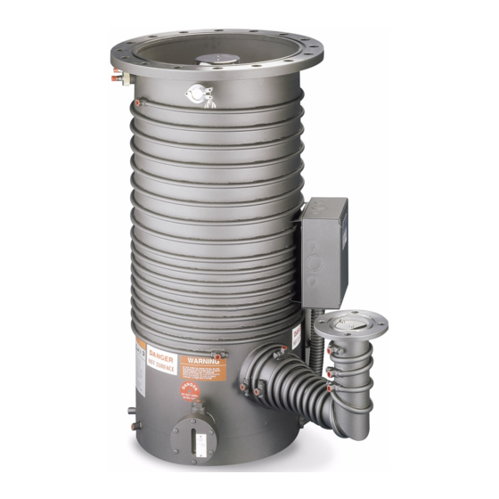
Page 23: Diffusion Pump Description
Technical Information Diffusion Pump Description Diffusion pumps are used where throughput for heavy gas loads is important. The diffusion pumps begin to work at approximately 10 Torr after a mechanical backing pump has exhausted most of the air in the system. Figure 2 HS-20 Diffusion Pump There are no moving parts in a diffusion pump, the heart of which is the multistage jet assembly, a group of concentric cylinders that are capped to leave small... -
Page 24: Pump Operation
Technical Information Pump Operation The diffusion pump works by heating the pump fluid to its boiling point. The vapors travel upward inside the jet assembly and are accelerated out and downward through the jet nozzles toward the cool outer walls of the pump, where the vapor condenses back into a fluid. - Page 25 Technical Information High Throughput Diffusion Pumps User Manual...
- Page 26 Technical Information High Throughput Diffusion Pumps User Manual...
-
Page 27: Pump Air Speed And Throughput
This relationship is shown for the large vacuum pumps in the set of graphs shown in Figure 3 through Figure 6. Figure 3 HS-16 Speed and Throughput Curves, 8.1 kW Figure 4 HS-20 Speed and Throughput Curves... - Page 28 Technical Information Figure 5 HS-32 Speed and Throughput Curves Figure 6 NHS-35 Speed and Throughput Curves High Throughput Diffusion Pumps User Manual...
-
Page 29: Physical Specifications
Technical Information Physical Specifications Table 5 HS-16: Dimensions and Weights Figure 7 HS-16 Outline with ASA Flanges Table 6 HS-16 Flange Dimensions High Throughput Diffusion Pumps User Manual... - Page 30 Technical Information Table 7 HS-20: Dimensions and Weights Figure 8 HS-20 Outline with ASA Flanges Table 8 HS-20 Flange Dimensions High Throughput Diffusion Pumps User Manual...
- Page 31 Technical Information Table 9 HS-32: Dimensions and Weights Figure 9 HS-32 Outline with ASA Flanges Table 10 HS-32 Flange Dimensions High Throughput Diffusion Pumps User Manual...
- Page 32 Technical Information Table 11 NHS-35: Dimensions and Weights Figure 10 NHS-35 Outline with ASA Flanges Table 12 NHS-35 Flange Dimensions High Throughput Diffusion Pumps User Manual...
-
Page 33: Unpacking
Technical Information Unpacking Before lifting a pump, check the weight of the equipment in Table 4. • WARNING Use power-assisted equipment, and trained moving and installation • personnel to avoid dropping, slipping, and overturning the pump and severely injuring personnel. Do not stand under equipment being moved. -
Page 34: Cleaning A New Pump
Technical Information Cleaning a New Pump A new pump requires cleaning only if the desired vacuum is below 1x10 Torr. NOTE Cleaning Safety Cleaning a diffusion pump involves the use of acetone and alcohol, both of which are toxic and explosive. Take careful note of the following information and warnings before starting a cleaning process. -
Page 35: Disassembly For Initial Cleaning
Technical Information Disassembly for Initial Cleaning This procedure involves the cleaning of the following elements: Jet assembly Drain plugs Sight glass Pump interior To disassemble the pump: Remove the cold cap as described in “Cold Cap”. Disassemble the internal jet system from the body of the pump in accordance with the appropriate procedure within “Jet Assemblies”. -
Page 36: System And Utility Connections
Technical Information System and Utility Connections WARNING Utility failure can cause overheating, damage to the equipment and explosion. Design your system to protect personnel and property from these hazards. Vacuum Connections The pump body must be installed vertical and plumb. Check that the mating flange on the system is horizontal ±1 °... -
Page 37: Cooling Water
does not exceed 130 °F (54 °C). Parallel connections should be employed when the water pressure is low or if the discharge temperature routinely exceeds 130 °F. Figure 11 HS-16/20 Cooling Water Connections High Throughput Diffusion Pumps User Manual... -
Page 38: Quick Cool Coil Connection
Technical Information To connect cooling water HS-32/NHS-35: Connect all body and foreline cooling in series except the Quick Cool coil. Connect the Cold Cap cooling coil separately (Figure 12). Refer to Table 4 for the cooling water flow rate. Higher flows will not harm the pump. If the diffusion pump is being cooled by a recirculating water system, ensure the system is capable of: Adequate cooling and heat exchange to ensure a continuous inlet... -
Page 39: Obtaining High Vacuum On The Nhs-35
Technical Information Obtaining High Vacuum on the NHS-35 When operating at low pressures (below 1x10 Torr), the ultimate pressure can be lowered by bypassing the por- tion of the cooling coils located at the bend of the foreline as shown in Figure 10. This procedure raises the temperature of the foreline and provides additional degassing of the fluid returning to the boiler, thus making lower pressures possible. - Page 40 Technical Information Table 13 Wiring Diagram Locations Source Voltage HS-16 Wiring HS-20 Wiring HS-32 Wiring NHS-35 Wiring 200 Delta Figure 15 208 Delta Figure 13 Figure 15 220 Delta Figure 15 Figure 17 Figure 20 240 Delta Figure 13 Figure 15...
- Page 41 Technical Information To wire the pump: Check the heater for correct supply voltage and find the appropriate wiring diagram. The correct voltage is shown. Check load balance by measuring the resistance of each branch. The heater resistances are given on their respective wiring diagrams. Make the connections to the terminals in the electrical main junction box at the foreline shown in the appropriate outline drawing.
-
Page 42: Overheating: Detection By Thermal Switches
These switches are set at the factory and do not require adjustment. The cutout temperatures for the water and boiler switches are given in the following table. Table 14 Thermal Cutout Temperatures Units HS-16 HS-20 HS-32 NHS-35 Water Switch °F... - Page 43 Technical Information Figure 13 HS-16 3-Phase Delta Circuit Table 15 HS-16 3 Phase Delta NORMINAL HEATER RESISTANCE @ LINE TO LINE RESISTANCE (OHMS) LINE CURRENT (AMPS) ROOM TEMPERATURE (OHMS) L1-L2/L2-L3/L3-L1 2700 W 3200 W 8100 WATTS 9600 WATTS 8100 WATTS 9600 WATTS 208 V = 12.8...
- Page 44 Technical Information Figure 14 HS-16 3-Phase WYE Circuit Table 16 HS-16 3 Phase WYE NORMINAL HEATER RESISTANCE @ LINE TO LINE RESISTANCE (OHMS) LINE CURRENT (AMPS) ROOM TEMPERATURE (OHMS) L1-L2/L2-L3/L3-L1 2700 W 3200 W 8100 WATTS 9600 WATTS 8100 WATTS 9600 WATTS 240 V = 20.3...
- Page 45 Technical Information Figure 15 HS-20 3-Phase Delta Parallel Circuit Table 17 HS-20 3-Phase Delta Parallel NORMINAL HEATER RESISTANCE @ LINE TO LINE RESISTANCE (OHMS) LINE CURRENT (AMPS) ROOM TEMPERATURE (OHMS) L1-L2/L2-L3/L3-L1 2000 W 12000 Watts 12000 Watts 200 V = 19 200 V = 6.3 34.6 208 V = 20.5...
- Page 46 Technical Information Figure 16 HS-20 3-Phase WYE Parallel Circuit Table 18 HS-20 3-Phase WYE Parallel NORMINAL HEATER RESISTANCE @ LINE TO LINE RESISTANCE (OHMS) LINE CURRENT (AMPS) ROOM TEMPERATURE (OHMS) L1-L2/L2-L3/L3-L1 2000 W 12000 Watts 12000 Watts 220 V = 22.9 380 V = 22.8 18.2 240 V = 27.3...
- Page 47 Technical Information Figure 17 HS-32 3-Phase Delta Parallel Circuit Table 19 HS-32 3-Phase Delta Parallel NORMINAL HEATER RESISTANCE @ LINE TO LINE RESISTANCE (OHMS) LINE CURRENT (AMPS) ROOM TEMPERATURE (OHMS) L1-L2/L2-L3/L3-L1 4000 W 24000 Watts 24000 Watts 220 V = 11.5 220 V = 3.8 240 V = 13.7 240 V = 4.5...
- Page 48 Technical Information Figure 18 HS-32 3-Phase WYE Parallel Circuit Table 20 HS-32 3-Phase WYE Parallel NORMINAL HEATER RESISTANCE @ LINE TO LINE RESISTANCE (OHMS) LINE CURRENT (AMPS) ROOM TEMPERATURE (OHMS) L1-L2/L2-L3/L3-L1 4000 W 24000 Watts 24000 Watts 240 V = 13.7 415 V = 13.6 33.4 High Throughput Diffusion Pumps User Manual...
- Page 49 Technical Information Figure 19 HS-32 3-Phase Delta Series Circuit Table 21 HS-32 3-Phase Delta Series NORMINAL HEATER RESISTANCE @ LINE TO LINE RESISTANCE (OHMS) LINE CURRENT (AMPS) ROOM TEMPERATURE (OHMS) L1-L2/L2-L3/L3-L1 4000 W 24000 Watts 24000 Watts 240 V = 13.7 480 V = 18.2 28.9 High Throughput Diffusion Pumps User Manual...
- Page 50 Technical Information Figure 20 NHS-35 3-Phase Delta Parallel Circuit Table 22 NHS-35 3-Phase Delta Parallel NORMINAL HEATER RESISTANCE @ LINE TO LINE RESISTANCE (OHMS) LINE CURRENT (AMPS) ROOM TEMPERATURE (OHMS) L1-L2/L2-L3/L3-L1 4000 W 24000 Watts 24000 Watts 220 V = 11.5 220 V = 3.8 240 V = 13.7 240 V = 4.5...
- Page 51 Technical Information Figure 21 NHS-35 3-Phase WYE Parallel Circuit Table 23 NHS-35 3-Phase WYE Parallel NORMINAL HEATER RESISTANCE @ LINE TO LINE RESISTANCE (OHMS) LINE CURRENT (AMPS) ROOM TEMPERATURE (OHMS) L1-L2/L2-L3/L3-L1 4000 W 24000 Watts 24000 Watts 240 V = 13.7 415 V = 13.6 33.4 High Throughput Diffusion Pumps User Manual...
- Page 52 Technical Information Figure 22 NHS-35 3-Phase Delta Series Circuit Table 24 NHS-35 3-Phase Delta Series NORMINAL HEATER RESISTANCE @ LINE TO LINE RESISTANCE (OHMS) LINE CURRENT (AMPS) ROOM TEMPERATURE (OHMS) L1-L2/L2-L3/L3-L1 4000 W 24000 Watts 24000 Watts 240 V = 13.7 480 V = 18.2 28.9 High Throughput Diffusion Pumps User Manual...
-
Page 53: Initial Vacuum Test
Technical Information Initial Vacuum Test Before charging the pump with fluid, carry out this initial vacuum test to establish the tightness of the system and its vacuum connections. Pumps and their components are designed for vacuum service; they are not designed to be pressurized which could cause them to burst possibly expelling shrapnel at lethal velocities. -
Page 54: Adding Or Changing Pump Fluid
Technical Information Adding or Changing Pump Fluid The risk of explosion on large vacuum diffusion pumps is increased by WARNING these factors: • Use of a hydrocarbon fluid as the pumping fluid. Hydrocarbon fluid is more prone to explosion than synthetic silicone-based fluid. If a hydrocarbon fluid is being used, check the entire system under vacuum before operating the pump. - Page 55 Technical Information To add or change pump fluid: Locate the fill and drain fittings in the appropriate outline drawing. Refer to Figure 7 through Figure 10. The fittings have special Viton® elastomer sealed plugs. Assure that the power to the heaters is off. Wait until the pump has cooled then vent it to the atmosphere.
-
Page 56: Operation
Technical Information Operation During initial installation, the newly installed pump fluid may be subjected to degassing. This may result in foreline pressure fluctuations that are considered normal. The following conditions increase the risk of explosion: WARNING • Air leaks into the system •... -
Page 57: Startup Procedure
Technical Information Startup Procedure To start the pump: Evacuate the diffusion pump using a mechanical roughing pump to below 0.5 Torr (0.67 mbar). The diffusion pump will not function unless the discharge pressure is less than the tolerable forepressure. Turn on the cooling water supply to the pump body and check that adequate flow is provided by examining the amount of water discharged at the visual drain points To prevent harmful collection of condensate on the boiler plate, heater, and... -
Page 58: Shutdown Procedure
Technical Information Shutdown Procedure 1 Releasing or admitting air to a pump with a hot boiler, especially when it is WARNING under vacuum, permits a strong oxidizer to contact the hot pump fluid and greatly increases the risk of an explosion. 2 Boiler temperatures reach 530°... -
Page 59: Maintenance
Technical Information Maintenance Perform these periodic checks to assure trouble-free operation. This maintenance prevents costly down-time and cleaning procedures. Maintain a day-to-day log of pump and system performance to identify marked variations that require corrective action. Periodic Inspections The maximum interval between inspection of the pump is established on the basis of experience. -
Page 60: Cleaning
Technical Information Cleaning Cleaning Safety Cleaning a diffusion pump involves the use of acetone and alcohol, both of which are toxic and explosive. Take careful note of the following warnings before starting a cleaning process. When heated, sprayed or exposed to high temperature equipment, these solvents become flammable and explosive, causing serious injury or death. - Page 61 Technical Information Complete cleaning of the pump may be required due to gradual deterioration of pump fluids. Removal of the pump from the system is then necessary. To clean an installed pump: Disconnect all water cooling lines and break the primary circuit supplying power to the pump heaters.
-
Page 62: Disassembly And Reassembly Procedures
Technical Information Disassembly and Reassembly Procedures Cold Cap To disassemble the cold cap, refer to the following figure and take the following steps. The halo baffle is disassembled in the same manner. NOTE Remove the female coupling, nut, follower, and gasket located at the end of the cold cap water line on the outside of the pump. - Page 63 Technical Information Supply water tubing must be connected to the cold cap coupling with FPT threads. NOTE Figure 24 Cold Cap Assembly High Throughput Diffusion Pumps User Manual...
-
Page 64: Jet Assemblies
Jet Assemblies The jet assemblies of each of the pumps are discussed and shown in the following subsections. Procedures and drawings are specific to each pump model. HS-16 Jet Assembly Figure 25 HS-16 Jet Assembly High Throughput Diffusion Pumps User Manual... - Page 65 Technical Information To disassemble the jet assembly: Remove the cold cap or halo baffle as described in “Cold Cap”. Unscrew the top cap from its coupling and remove it. Remove the top plug. Remove the drip shield that sits loosely on the 2nd stage. Lift and remove the entire 2nd stage.
-
Page 66: Hs-20 Jet Assembly
Technical Information HS-20 Jet Assembly Figure 26 HS-20 Jet Assembly High Throughput Diffusion Pumps User Manual... - Page 67 Technical Information To disassemble the jet assembly: Remove the cold cap or halo baffle as described in “Cold Cap”. Unscrew the jet cap from the coupling assembly. Remove the orifice plug. Withdraw the central tube complete with the second stage jet and jet shield. Remove the lower jet assembly from the pump, which consists of the third stage jet, the jet shield, the fourth stage jet, and the jet base.
- Page 68 Technical Information Follow steps 1 through 5 in reverse order. If the jet coupling loosens from the jet rod during disassembly, position it so that NOTE the top of the jet coupling is flush with the bottom orifice plug (Figure 27). Figure 27 Jet Coupling Detail High Throughput Diffusion Pumps User Manual...
-
Page 69: Hs-32 Jet Assembly
Technical Information HS-32 Jet Assembly Figure 28 HS-32 Jet Assembly To disassemble the jet: Unscrew and remove the hex nut holding the cold cap in place. Note its orientation prior to removal. Remove the cold cap (or halo baffle) as described in “Cold Cap”. Remove the nut, washer, and the top jet cap from the center jet rod. - Page 70 Technical Information To reassemble the jet: If the center jet rod was removed or loosened during disassembly, thread the rod back into the boilerplate. The top of the rod should be roughly 1/16" to 1/8" below the top surface of the inlet flange (inlet plane of the pump). Once properly located, use the nut near the boilerplate to lock the rod in place.
-
Page 71: Nhs-35 Jet Assembly
Technical Information NHS-35 Jet Assembly Figure 29 NHS-35 Jet Assembly To disassemble the jet: Unscrew and remove the hex nut holding the cold cap in place. Note its orientation prior to removal Remove the cold cap (or halo baffle) as described in “Cold Cap”. Unscrew the top jet cap and remove. - Page 72 Technical Information To reassemble the jet: If the center jet rod was removed or loosened during disassembly, thread the rod back into the boilerplate. The top of the rod should be roughly 1/16" to 1/8" below the top surface of the inlet flange (inlet plane of the pump). Once properly located, use the nut near the boilerplate to lock the rod in place.
-
Page 73: Heater Replacement Procedure
Technical Information Heater Replacement Procedure The following figure shows the components of the heater element assembly. The heater replacement procedure is the same for all large diffusion pumps*. Use the following precautions when handling the fiberglass insulator and WARNING wires as the fiberglass insulator contains RCF, a potentially carcinogenic material. - Page 74 Technical Information Poor clamping resulting in inadequate thermal contact may result in reduced CAUTION heater life and poor pump performance. Tighten nuts finger-tight on clamping plate, then gradually and evenly tighten them to 250 inches-pounds of torque. To replace a heater: Use an ohmmeter at the electrical box to determine which heater element has failed.
- Page 75 Technical Information Screw on the remaining nut(s) finger-tight, then tighten all nuts evenly to 250 inches-pounds of torque. Check the heater alignment with the crush plate. The heater must be located inside the crush plate tabs on all three sides. Label the heater leads according to the schematic diagram.
-
Page 76: Troubleshooting
Technical Information Troubleshooting Leakage If leakage is the suspected cause of poor system performance, first check the following items: Inlet and foreline connections Drain and fill plugs Other compression fittings, such as high-vacuum gauges in the system Threaded connections, such as a foreline gauge. -
Page 77: Poor Pump Or System Performance
Technical Information Poor Pump or System Performance The following table lists the faults, the probable causes and corrective actions to take if you have a problem with a large diffusion pump. Table 25 Troubleshooting Guide Fault Probable Cause Corrective Action Poor system pressure Leaks in system, virtual or real Locate and repair... - Page 78 Technical Information Table 25 Troubleshooting Guide (Continued) Fault Probable Cause Corrective Action High chamber contamination Forepressure too high Check for leak in foreline, poor of the pump fluid mechanical pump performance, breakdown of pump fluid, and incorrect valve operation Prolonged operation in overload range Adhere to operating procedures Cutting over from the backing pump too Cut over at a lower chamber pressure...
-
Page 79: Accessories And Spare Parts
Technical Information Accessories and Spare Parts When ordering replacement parts, quote type number and serial number of pump. The following tables show the HS-16, HS-20, HS-32 and NHS-35 accessories and spare parts. Table 26 HS-16 Accessories and Spare Parts Part Number... - Page 80 Technical Information Table 26 HS-16 Accessories and Spare Parts (Continued) Part Number Description 79308001 Heater cover plate K0377164 O-ring kit; includes: ❑ 1 Butyl ASA inlet O-ring (48214001) ❑ 1 Buna-N ASA foreline O-ring (660890348) ❑ 8 Viton fill and drain O-rings (660892213) ❑...
- Page 81 Threaded plug, fill and drain K9050001 Upper thermal switch, Temperature setting: 185 °F K9050002 Lower thermal switch, Temperature setting: 390 °F X3900-68006 HS-16/20 thermo switch wire, 14 AWG, 80" length 648056329 Ni lug, 14 AWG X3900-68000 HS-16/20 heater wire, 120" 10 AWG 647320025...
- Page 82 Technical Information Table 27 HS-20 Accessories and Spare Parts (Continued) Part Number Description K7107001 Clamping plate L6514001 Insulation for heaters, Cerablanket 0.50" thick 84497001 Heater cover plate L9223001 Sight glass (for pumps built after October 1994) K0377165 O-ring kit; includes: ❑...
- Page 83 Technical Information Table 28 HS-32 Accessories and Spare Parts Part Number Description 77252801 Cold cap assembly, includes No.10-32 SST Rd Hd screw and No. 10-32 hex nut SST L8839301 Cold cap gasket kit F2622001 Cold cap follower (brass) 75786001 Cold cap nut 622445026 Cold cap female coupling, 1/2"...
- Page 84 Technical Information Table 29 NHS-35 Accessories and Spare Parts Part Number Description F1971302 Jet Assembly 81437301 Cold cap assembly (includes No.10-32 SST Rd Hd screw and No. 10-32 hex nut) SST L8839301 Cold cap gasket kit F2622001 Cold cap follower (brass) 75786001 Cold cap nut 622445026...
- Page 90 Request for Return Form United States India (Sales) India (Service) Agilent Technologies Agilent Technologies India Pvt. Ltd. Agilent Technologies India Pvt. Ltd. 121 Hartwell Avenue Unit Nos 110- 116, & Part of 101 & 109 C-Block, RMZ Centennial Plot Number- 8A, 8B, 8C,...
- Page 91 In This Book The manual describes the following: Contents Technical information www.agilent.com © Agilent Technologies, Inc. 2021 Edition G.00, 04/21 699901140...