Table of Contents
Advertisement
Quick Links
MODELS
TOUCAN 1010
U.S.A.
JLG INDUSTRIES, INC
1 JLG Drive
McConnellsburg
PA 17233-9533
Tel : (171) 485-5161
Fax : (717) 485-6417
Updated : 04-2006
C.E.
JLG Manufacturing Europe
Breitwaterstraat 12A
Oude Bunders 1034
B - 3630 Maasmechelen
Tel : +32(0)89 774 974
Fax : +32(0)89 777 427
FRANCE
JLG F rance SAS
Z.I. de Fauillet
BP 20 - 47400 TONNEINS
France
Tel : +33 553 84 85 11
Fax : +33 553 79 06 87
English - Service
MA0235-02
Advertisement
Table of Contents

Related Manuals for JLG TOUCAN 1010


Summary of Contents for JLG TOUCAN 1010
- Page 1 MODELS TOUCAN 1010 U.S.A. C.E. FRANCE JLG INDUSTRIES, INC JLG Manufacturing Europe JLG F rance SAS 1 JLG Drive Breitwaterstraat 12A Z.I. de Fauillet McConnellsburg Oude Bunders 1034 BP 20 - 47400 TONNEINS PA 17233-9533 B - 3630 Maasmechelen France...
- Page 3 Models _____ Toucan 1010 _____ Toucan 1010 I MA0235-02 Models Toucan 1010 Edition 04-2006...
-
Page 4: Table Of Contents
TABLE OF CONTENTS INTRODUCTION Foreword Important information WORK PLATFORM CHARACTERISTICS Description ------------------------------------------------------------------------------- 2.1 Characteristics - Dimensions - Performances --------------------------------- 2.2 PRESSURE SETTINGS Relief valve setting -------------------------------------------------------------------- 3.1 Brake release circuit pressure check -------------------------------------------- 3.2 Circuit relief valve adjustment ----------------------------------------------------- 3.3 Main pressure (PR1) ----------------------------------------------------------------- 3.3.1 Right swing (PR2) -------------------------------------------------------------------- 3.3.2 Left swing (PR3) ---------------------------------------------------------------------- 3.3.3... - Page 5 Main hydraulic power unit -------------------------------------------------------- 5.15 Steering bracket thrust washers ------------------------------------------------ 5.16 Mast section alignment ------------------------------------------------------------ 5.17 Lifting chains adjustment ---------------------------------------------------------- 5.18 Chain control and lubrication ----------------------------------------------------- 5.19 Control of chain wear ------------------------------------------------------------- 5.19.1 Chain lubrication ------------------------------------------------------------------- 5.19.2 Models Toucan 1010 Edition 04-2006...
- Page 6 TABLE OF CONTENTS ELECTRICAL CONTROLS DEVICE Overload detection setting ---------------------------------------------------------- 6.1 Tilt alarm --------------------------------------------------------------------------------- 6.2 Battery discharge indicator setting ----------------------------------------------- 6.3 Circuits protection --------------------------------------------------------------------- 6.4 Façade circuit-breaker ------------------------------------------------------------- 6.4.1 Resetable fuses ----------------------------------------------------------------------- 6.4.2 Fuses on board ------------------------------------------------------------------------ 6.4.3 Power circuit fuses ------------------------------------------------------------------ 6.4.4 Devices modifying the machine's performance ------------------------------ 6.5 Mast switch --------------------------------------------------------------------------- 6.5.1 "5 m"...
- Page 7 TABLE OF CONTENTS INTRODUCTION Foreword Important information Models Toucan 1010 Edition 04-2006...
- Page 8 FOREWORD This manual has been compiled to assist you in properly operating and maintaining your JLG Aerial Work Platform. The Work Platform has been designed for maximum performance with minimum maintenance. With proper care, years of trouble-free service can be expected.
- Page 9 : Safety, Operation Correctness, and Technical Content. All SMCAR's will be reviewed by the responsible Department at JLG. Approved SMCAR's will be distributed in a Service Bulletin immediately and then incorporated in the next scheduled change to the manual. An answer to the SMCAR, approved or disapproved, will be sent directly to the one submitting the SMCAR.
- Page 10 CORRECTIVE ACTION REQUEST This page intentionally left blank. Model T o ucan 1010 Révision 04-2006...
-
Page 11: Work Platform Characteristics
TABLE OF CONTENTS WORK PLATFORM CHARACTERISTICS 2.1. Description 2.2. Characteristics - Dimensions - Performances Models Toucan 1010 Edition 04-2006... -
Page 12: Description
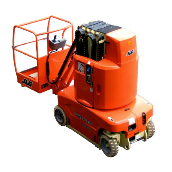
WORK PLATFORM CHARACTERISTICS 2.1 Description The work platform consists of a self-propelled all welded steel frame, a telescopic mast mounted on a turntable and a pendular jib. The platform is mounted at the end of the jib. The drive function is accomplished by two hydraulic motors which propel the rear axle. - Page 13 Counterweight Hand pump Breakdown control panel Steering hydraulic unit Steering wheels LEFT SIDE Front Rear Front battery access Platform controls Manual box Charger Emergency control panel Platform Counterweight Lateral battery access Steering wheels Driving wheels Models Toucan 1010 Edition 04-2006...
-
Page 14: Characteristics - Dimensions - Performances
WORK PLATFORM CHARACTERISTICS 2.2. Characteristics - Dimensions - Performances DIM ENSIONS (LOWERED) Standard platform Large platform Length 2,89 m 3,20 m Width 0,99 m Height 1,99 m Weight T 1010 3300 kg Weight T 1010 I 2650 kg Ground Clearance 0,08 m CAPACITY - M A NOEUVRA BILITY Platform floor min. - Page 15 Speeds are indicated for a machine with a fully charged battery and working in an ambiant temperature of 20°C. Constant product improvement make it necessary that JLG reserve the right to make specification and equipment changes without notice.
- Page 16 CORRECTIVE ACTION REQUEST This page intentionally left blank. Model T o ucan 1010 Révision 04-2006...
-
Page 17: Pressure Settings
3.3.2. Right swing (PR2) 3.3.3. Left swing (PR3) 3.3.4. Mast elevation (PR4) 3.3.5. Jib elevation (PR5) 3.3.6. Jib lowering (PR6) 3.3.7. Brake release maximum pressure (PR7) 3.3.8. Drive at low speed (PR8) 3.4. Counterbalance valve setting Models Toucan 1010 Edition 04-2006... - Page 18 CORRECTIVE ACTION REQUEST This page intentionally left blank.
-
Page 19: Relief Valve Setting
NOTE Test plug To adjust a relief valve turn the adjustment screw (in to increase or out to decrease) until the proper setting is reached. Models Toucan 1010 Edition 04-2006... -
Page 20: Brake Release Circuit Pressure Check
BRAKE RELEASE MAXIMUM 3- Remove the pressure gauge. PRESSURE in § 3.3.7. If the maximum reading is over 21 bar, consult your local JLG distributor 3.3.4. Mast elevation (PR4) for servicing. 5- Remove the pressure gauge. -
Page 21: Jib Lowering (Pr6)
5- Remove the pressure gauge. CAUTION If the pressure reading is lower than 15 bar or higher than 21 bar, consult your local JLG distributor for servicing. 7- TURN OUT the PR7 relief valve adjustment screw until the pressure drops just under the previously recorded value, then turn the adjustment screw 1/4 turn IN. -
Page 22: Counterbalance Valve Setting
PRESSURE SETTINGS The counterbalance valves on the drive manifold ensure 3.4 Counterbalance valves dynamic braking for the work platform. setting The more the setting screw is tightened, the sharper the braking is. - Mast/jib cylinder counterbalance valve. Setting must be performed with the rated load (200 kg) The valve opening pressure is factory pre-set at 210 evenly distributed in the platform. -
Page 23: Battery - Charger
4.7 Storage of a battery at temperatures below 0°C (32°F) 4.8 Use of a battery in a cold chamber or in a cold climate 4.9 Battery not working continuously or inactive battery 4.10 Battery troubleshooting Models Toucan 1010 Edition 04-2006... - Page 24 CORRECTIVE ACTION REQUEST This page intentionally left blank.
- Page 25 1 pack on both sides of the mast, 1 additional counterweight at the front - T1010 I : 1 pack at the front, 1 pack on the left hand side of the mast Batteries wiring T1010I (2 battery packs) Models Toucan 1010 Edition 04-2006...
- Page 26 BATTERY - CHARGER 4.2 Charger The work platform on-board electronic charger is designed to automatically charge 24 VDC (wet) lead- acid rechargeable batteries. DANGER Lead-aci d batteries may emi t hig hly explosive gases. The emission is greatly increased during charging. Never introduce flames, sparks, or other sources of ignition to battery area.
- Page 27 Leave the batteries to rest before resuming Batteries too discharged charge. Disconnect and reconnect the batteries. Contact Electronic safety. Safety time switch faulty JLG Product Support if the fault persists. Connect the battery from the work platform to Battery incorrect nominal voltage the charger. Models...
- Page 28 BATTERY - CHARGER 4.2.2 "Oldham-Hawker" charger NOTE A spare output fuse is strapped inside the charger cover. Power supply : 110VAC - 60Hz / 230VAC - 50Hz - Adaptation to network voltage : CP IV models DANGER Prior to any operation requiring charger cover removal, th e battery must be disconnected and the charger must be unplugged from the AC outlet.
- Page 29 (d) lights up. - the led (d) flashes as long as the charger is It is advised to have either the charger or the battery not connected to the power supply. checked by a technician. Models Toucan 1010 Edition 04-2006...
- Page 30 Disconnect the charger from the battery Charging time exceeds 15 hours (Voltage above and connect it again. If the problem persists, contact 2,4V per cell) (Soft timer #2). JLG Product Support. Charging time exceeds 16 hours (Hard timer). Model T o ucan 1010...
-
Page 31: Battery Filling
Battery cells filling must be performed only 2 0 % 4 0 % 6 0 % 8 0 % 100% after charge (during charge, electrolyte level Discharge depth in % increases and can overflow). Filling battery cells : Flow indicator Models Toucan 1010 Edition 04-2006... -
Page 32: Centralised Filling System Maintenance
BATTERY - CHARGER Checking electrolyte specific gravity : 4.5. Centralised filling system maintenance DANGER Battery electrolyte must not be allowed to It is necessary to service the centralised filling system contact the skin or eyes. If it does occur, flush at least once a year. -
Page 33: Cleaning - Battery Maintenance
To drain the water : 1- Fill the draining bulb with water (a draining bulb is supplied with the work platform). Models Toucan 1010 Edition 04-2006... -
Page 34: Use Of A Battery In A Cold Chamber Or In A Cold Climate
BATTERY - CHARGER 4.9. Battery working 4.7. Storage of a battery at continuously or inactive battery temperatures below 0°C (32 °F) A battery which is not used or used by intermittence Prior to battery storage at temperatures below 0°C ( must be stored charged in a dry area away from 32 °F), electrolyte specific gravity must be verified in freezing temperatures. -
Page 35: Battery Troubleshooting
Loss of electrolyte due to overflow. Perform an equalization charge. gravity or electrolyte specific gravity too low. Stratification of the electrolyte. Contact your JLG Distributor/Product Support. Electrolyte specific gravity too low. Refer to "electrolyte specific gravity too Low voltage in the cells in open low". - Page 36 CORRECTIVE ACTION REQUEST This page intentionally left blank.
-
Page 37: Maintenance
5.13 Fasteners and torque values 5.14 Steering switches 5.15 Main hydraulic power unit 5.16 Steering bracket thrust washers 5.17 Mast section alignment 5.18 Lifting chain adjustment 5.19 Chain control and lubrication 5.19.1 Control of chain wear 5.19.2 Chain lubrication Models Toucan 1010 Edition 04-2006... - Page 38 CORRECTIVE ACTION REQUEST This page intentionally left blank.
-
Page 39: Cleanliness
- Rust preventive compound has been removed ensure that nothing has been overlooked. from all machined surfaces of new parts before - Recheck various adjustments by operating the they are installed (except leaf chains). machine before returning it to the job. Models Toucan 1010 Edition 04-2006... -
Page 40: Parts Replacement
MAINTENANCE 5.8.3. Bushings and pin 5.5. Parts replacement - When installing pin, proper care must be taken Parts found damaged or out of tolerance during to ensure bushing and pin are properly aligned maintenance should be replaced. Refer to the so that bushing coating is not damaged. -
Page 41: Mast Roller Removal
Flange bushings CAUTION Hold the bronze spacer, roller and washer to prevent any of them from falling to the bottom of the mast. CAUTION Install the roller before removing another one (refer to § 5.9.3). Models Toucan 1010 Edition 04-2006... -
Page 42: Lower Rollers
MAINTENANCE Grease 5.9.2. Lower rollers. NOTE Before removing the lower rollers, ensure the upper rollers are installed. Using ground controls : 1- Raise the telescopic mast to gain access to the roller to be removed. 2- Unscrew the locknut from the roller to be removed using a polygonal spanner. -
Page 43: Hydraulic System
Installation of new elements is always suspected to have entrapped air that may be recommended. pressurized. Failure to comply could result in death or injury to personnel. Models Toucan 1010 Edition 04-2006... -
Page 44: Fatigue Of Welded Structures
If you require more detailed inspection instructions is in operation. Failure to comply could result and/or repair procedures, contact your local JLG in death or injury to personnel. distributor for assistance. If air entrapment should persist, it may become... -
Page 45: Fasteners And Torque Values
Torque tables are provided by JLG for reference when preforming maintenance. Use of proper torque values is extremely important. Improper torquing can seriously affect performance and reliability. - Page 46 MAINTENANCE Nut identification : Grade 8.8 Grade 10.9 Grade 12.9 Bolt identification : STUD Grade 8.8 HEX. HEAD BOLT 10.9 12.9 SOCKET HEAD BOLT 10.9 12.9 Grade 8.8 Grade 10.9 Grade 12.9 Torque value for wheel nuts : - Front : 150 N.m - Rear : 170 N.m The values in the charts below correspond to the use of galvanised fasteners in their delivery condition: no grease, nor degreaser.
-
Page 47: Steering Switches
45°. The left hand side lower switch limits the steering to the left when the steering angle of the left steering wheel reaches 45°. Models Toucan 1010 Edition 04-2006... -
Page 48: Main Hydraulic Power Unit
MAINTENANCE 5.15 Main hydraulic power unit 5.16 Steering bracket thrust washers Main hydraulic power unit motor brushes (Qty = 4) have to be regularily checked. Motor ventilation holes have to be regularily cleaned by blowing compressed air through the holes as indicated below : Brushes removal : 1- Disconnect the battery plug. -
Page 49: Lifting Chains Adjustment
- Check the torque value of all roller pin locknuts. ensuring the final offset of the Deflection mast sections is kept. Do not hesitate to contact your approved JLG distributor for more information. 6- Check the presence and correct tightening of the locknut on each chain anchor. -
Page 50: Chain Control And Lubrication
MAINTENANCE If a chain appears to be faulty or worn, it must be 5.19 Chain control and lubrication replaced ; the condition of the pulleys and the telescopic mast alignment must be checked. The service life of a lifting chain depends on the work platform operating conditions and on the environment 5.19.2 Chains lubrication. -
Page 51: Electrical Controls Device
6.5.4 Drive limit switch 6.5.5 Safety features - Movement cut out 6.6 Speed electronic controller 6.7 Help with the diagnosis 6.8 Electronic modules 6.8.1 Controls verification module 6.9 Drive management module 6.10 "Clipper" connector installation procedure Models Toucan 1010 Edition 04-2006... -
Page 52: Overload Detection Setting
ELECTRICAL CONTROLS DEVICE Setting : 6.1 Overload detection setting 1- Place a 200 kg load evenly distributed on the Check : platform floor. 2- Loosen the locknut of the setting screw. 1- Place a 200 kg load evenly distributed on the 3- Loosen the setting screw until the sensor is platform floor. -
Page 53: Tilt Alarm
4- With a jack of appropriate capacity, lift the front À of the chassis in - An acoustic alarm sounds when the chassis is tilted at 2°. - The corresponding LED alarm lights up on platform controls. Models Toucan 1010 Edition 04-2006... -
Page 54: Battery Discharge Indicator Setting
ELECTRICAL CONTROLS DEVICE 6.3 Battery discharge indicator setting Ba tte ry Ba tte ry 280 Ah 600 Ah "LED" To adjust the cut out threshhold, proceed as follows: battery discharge - Measure the battery electrolyte density when indicator the power is cut off (both red leds flash alternately). -
Page 55: Circuits Protection
30 seconds after the power has been cut off, the componant is automatically reset. : 7A MPERAGE CAUTION : Emergency control panel. OCATION The componant temperature under the influence of a fault current may reach 125°C. Models Toucan 1010 Edition 04-2006... - Page 56 ELECTRICAL CONTROLS DEVICE : Electronic card OCATION a- Main board 1 - Platform control box 2- Emergency control box Refer to the electrical schematic to locate the protected lines. Model T o ucan 1010 Révision 04-2006...
-
Page 57: Fuses On Board
F1, F2, F3, F5, F6, F7 : Quick fuse ATO 1 A. F4 : Quick fuse ATO 2 A. : protection of the steering unit motor UNCTION supply. : 63A MPERAGE : C20 : Steering bar OCATION Models Toucan 1010 Edition 04-2006... -
Page 58: Devices Modifying The Machine's Performance
ELECTRICAL CONTROLS DEVICE 6.5.3. Steering limit switch 6.5 Devices modifying the machine's performance Location : Steering bar Wiring : Independant switches, wired in parallel These switches, mechanical or electronical, are with the relay contacts K3. normally open when actuated. They cause the power cut off of the served elements. -
Page 59: Safety Features - Movement Cut Out
ç Supplied relay, corresponding lit. Additional relay (k6) : supplied when a non authorized movement is actuated. : Dump valve coil of the hydraulic group UNCTION removal (DV). Relay k5 : authorize overload static detection. Models Toucan 1010 Edition 04-2006... -
Page 60: Speed Electronic Controller
ELECTRICAL CONTROLS DEVICE 6.6 Speed electronic controller The motor speed controller fitted to the work platform enables fluctuation of the rotation speed of the main hydraulic unit motor, therefore modifying the speed of the work platform movements. The controller presents eight programmable speeds : - Six variable speeds (four are used). - Page 61 ELECTRICAL CONTROLS DEVICE Description and parameters values for Toucan 1010 models. Values Parameter Description Unit Step Comments Groupe Centrale Bosch Advanced Mast lowering movement. Speed 1 Speed n°1 (variable) Make-up flow to hydraulic wheel motor. Jib lowering movement. Speed 2 Speed n°2 (variable)
- Page 62 ELECTRICAL CONTROLS DEVICE Calibrator use as operating control instrument (test Diagnostic Led : mode) : The controller is equipped with a diagnostic system - Position the control panel selector either to using a green LED located near the calibrator socket. "platform controls"...
-
Page 63: Help With The Diagnosis
Jib elevation û Jib lowering û û Structure slewing Right Structure slewing Left û Drive Forward û Drive Reverse û û Steering Left û Steering Right Selection drive speed 2 û Selection drive speed 3 û Models Toucan 1010 Edition 04-2006... - Page 64 ELECTRICAL CONTROLS DEVICE : Electronic card emergency control panel. OCATION Marking Component or function Input State Output LK3 - 4 Relay K3 + relay K4 û Relay K5 û û Relay K6 Relay K7 û Relay K8 û û Relay K9 û...
- Page 65 : Controls verification module. OCATION Led 1 : Movement authorization Led 2 : Drive movements Led 3 : Inverse of Led 2 Led 4 : Structure movement Led 5 : Pump Inhibit Led 6 : platform inclination Models Toucan 1010 Edition 04-2006...
- Page 66 ELECTRICAL CONTROLS DEVICE Inputs Condition Command Control Module Alarms Condition MM DM MB DB OD OG DD DG LK1 LK2 SP2 SP3 LD1 LD2 LD3 LD4 LD5 LD6 H2 L1 L2 L3 L4 L5 MAv MAr Norm Overload ® ® 1°...
- Page 67 • Steering switches (T910 - T1010 only) ‚ : Steering without driving - In motion : associated to precedent cases ƒ : Tilt sensor (T800 - T870 only) „ : Movements accomplished in work position Models Toucan 1010 Edition 04-2006...
-
Page 68: Electronic Modules
ELECTRICAL CONTROLS DEVICE 6.8 Electronic modules 6.8.1 Controls verification module UNCTION - Authorization of the control movement execution if and only if the "Dead man" device (enable pedal) is actuated before the control of the desired movement : the controls must be in neutral before the action on the enable pedal. - Page 69 The reset push button on the platform ç LED [LD4] lights up. control panel allows to "force" entry [E10] to 24 V ; it must be actuated and held before the enable pedal is depressed. Models Toucan 1010 Edition 04-2006...
-
Page 70: Drive Management Module
ELECTRICAL CONTROLS DEVICE 6.9 Drive management module Architecture of the module MODULE Regulated supply E1 - E2 RIVE MANAGEMENT ELAY MANAGEMENT ON THE ANAGEMENT OF THE OVERLOAD ALARM ACTUATION STRUCTURE MOVEMENTS ♦ Start sequence ♦ Stop sequence E16 - E22 - E23 ♦... - Page 71 Input signal of structure in lowered position Not used Forced supply to overload relay Not used Input auxillary sensor for authorization of simultaneous lowering Input Jib lowering control Input Mast lowering control Supply to coil [DB] Supply to coil [DM] Models Toucan 1010 Edition 04-2006...
- Page 72 ELECTRICAL CONTROLS DEVICE Progressive start / stop sequence ( STARTING SEQUENCE / PROGRESSIVE STOPS [E3] or [E4] t = 1s t = 2s mini [E13] [E8] or [E9] [E15] [E19] and [E20] 2 t = 4s [E17] 4 x t = 4s t = 2s [E11] 100%...
- Page 73 [E3] or [E4] t = 1s t = 2s mini [E13] [E8] or [E9] [E15] [E19] and [E20] 2 x t = 4s [E17] t = 2s 4 x t = 4s [E11] 100% 30° 0° Models Toucan 1010 Edition 04-2006...
- Page 74 ELECTRICAL CONTROLS DEVICE Starting sequence / sudden reversal of drive direction ( [E3] [E4] t = 1s t = 2s mini [E13] [E8] t =1s [E9] [E15] [E19] and [E20] [E17] 4 x t = 4s 4 x t = 4s [E11] 100% 30°...
- Page 75 Potentiometer P3 : Temporisation for make up flow and braking [t2] NOTE A small jerk occurs when the machine switches from ( ) gear to ( ) gear or from ( ) gear to ( ) gear. . Models Toucan 1010 Edition 04-2006...
- Page 76 ELECTRICAL CONTROLS DEVICE - Finer adjustments : Potentiometer (P3) : 1. Place the drive speed selector to ( Potentiometer (P1) : 2. Perform a forward drive movement at maximum speed. 1. Position the drive speed selector to ( 3. Release the enable pedal. The platform should 2.
- Page 77 - Pinch the holding clips once all the contacts are inserted. Crimping tool : Clipper ref. : Y16SCM-GL3 Putting the contact in place 1. Tie the cable and connector assembly with a plastic strap TERMINAL BLOCK MUST BE DONE WITHOUT EFFORT ! Models Toucan 1010 Edition 04-2006...
- Page 78 ELECTRICAL CONTROLS DEVICE Check the red plate is correctly inserted in the black NOTE connector body. If impossible to correctly wire the connector, remove the red retaining plate : locating sprockets should not be broken. b r o k e n sprocket If the terminal is hard or impossible to push in, check the contacts are correctly inserted in their housing...
- Page 79 7.2.3 Monthly preventive maintenance and inspection 7.2.4 Every 125 hours of operation preventive maintenance and inspection 7.2.5 Every 250 hours of operation preventive maintenance and inspection 7.2.6 Every 500 hours of operation preventive maintenance and inspection Models Toucan 1010 Edition 04-2006...
- Page 80 CORRECTIVE ACTION REQUEST This page intentionally left blank.
-
Page 81: General
The information in this section point out the items to - Electrical boxes and components, be checked when performing daily, weekly and time - The electronic controller, based maintenance and inspections required on JLG - The battery, aerial work platforms. - The charger,... -
Page 82: Preventive Maintenance And Inspection Required
PREVENTIVE MAINTENANCE AND INSPECTION 7.2.2. Weekly preventive maintenance 7.2. Preventive maintenance and and inspection inspection required Weekly preventive maintenance/inspections should include verification of the following items : CAUTION Control and maintenance intervals must be - Wheels nuts respected to ensure safe operation of the - Hydraulic hoses and fittings work platform. -
Page 83: Every 500 Hours Of Operation Preventive Maintenance And Inspection
NOTE Turntable attachment caps screws have to be retorqued after the first 100 hours operation. NOTE Hydraulic filters have to be replaced after the first 50 hours operation. Models Toucan 1010 Edition 04-2006... - Page 84 CORRECTIVE ACTION REQUEST This page intentionally left blank.
-
Page 85: Lubrication
TABLE OF CONTENTS LUBRICATION 8.1 Lubrication points Models Toucan 1010 Edition 04-2006... - Page 86 CORRECTIVE ACTION REQUEST This page intentionally left blank.
-
Page 87: Lubrication Points
(Lithium base grease) cleaning or more often 1. Mast profiles if the work platform is MOBILITH SHC 220 used or stored in a very (Low temperature) dusty or corrosive environment. 3. Cycle the mast and relubricate. Models Toucan 1010 Edition 04-2006... - Page 88 LUBRICATION LOCATION LUBE TYPE LUBE INTERNAL LUBE AMOUNT APPLICATION Lubricant can be applied manually with a brush or by Every 125 hours or spraying. once every 30 days of Apply lubricant : MOBIL DTE 16M operation or more often - Longitudinally = in areas where Viscosity : 68 cSt at 40°C 2.
- Page 89 NOTES Models Toucan 1010 Edition 04-2006...
Need help?
Do you have a question about the TOUCAN 1010 and is the answer not in the manual?
Questions and answers