JLG T500J Operation And Safety Manual
Hide thumbs
Also See for T500J:
- Quick start manual ,
- Service and maintenance manual (306 pages) ,
- Operating instructions (3 pages)

Related Manuals for JLG T500J


Summary of Contents for JLG T500J
- Page 1 Operation and Safety Manual Original Instructions - Keep this manual with the machine at all times. Trailer Mounted Boom Lift Models T350 T500J ANSI P/N - 3121197 ® May 21, 2014...
- Page 3 The purpose of this manual is to provide owners, users, operators, lessors, and lessees with the precautions and operating procedures essential for the safe and proper machine operation for its intended purpose. Due to continuous product improvements, JLG Industries, Inc. reserves the right to make specification changes without prior notification. Contact JLG Industries, Inc. for updated information.
- Page 4 INDICATES INFORMATION OR A COMPANY POLICY THAT RELATES DIRECTLY OR INDI- INDICATES A POTENTIALLY HAZARDOUS SITUATION. IF NOT AVOIDED, COULD RECTLY TO THE SAFETY OF PERSONNEL OR PROTECTION OF PROPERTY. RESULT IN SERIOUS INJURY OR DEATH. THIS DECAL WILL HAVE AN ORANGE BACK- GROUND. – JLG Lift – 3121197...
- Page 5 Modifications Product Safety JLG INDUSTRIES, INC. SENDS SAFETY RELATED BULLETINS TO THE OWNER OF RECORD OF THIS MACHINE. CONTACT JLG INDUSTRIES, INC. TO ENSURE THAT THE Contact: CURRENT OWNER RECORDS ARE UPDATED AND ACCURATE. Product Safety and Reliability Department JLG Industries, Inc.
- Page 6 Revised - January 30, 2006 Revised - May 1, 2007 Revised - December 9, 2009 Revised - May 11, 2010 Revised - April 4, 2012 Revised - August 29, 2012 Revised - May 21, 2014 – JLG Lift – 3121197...
-
Page 7: Table Of Contents
PREPARATION, INSPECTION, AND MAINTENANCE ..2-2 Pre-Start Inspection....... . 2-4 3121197 – JLG Lift –... - Page 8 From the Ground Console ......5-7 From the Platform Console (Drive & Set Only) ..5-8 – JLG Lift – 3121197...
- Page 9 (ANSI Machines) ........7-4 3121197 – JLG Lift –...
- Page 10 Position of Least Backward Stability (T350) ... 5-3 5-3. Position of Least Forward Stability (T500J) ... . 5-4 5-4. Position of Least Backward Stability (T500J)... 5-5 5-5.
-
Page 11: Section - Paragraph, Subject Page Section - Paragraph, Subject Page
Component Weights - T350 ......7-6 7-11 Component Weights - T500J ......7-6 7-12 Hydraulic Oil . - Page 12 TABLE OF CONTENTS SECTION - PARAGRAPH, SUBJECT PAGE SECTION - PARAGRAPH, SUBJECT PAGE This page left blank intentionally. – JLG Lift – 3121197...
-
Page 13: Section 1. Safety
If there are any questions with regard to safety, training, inspec- • Only authorized and qualified personnel can operate the tion, maintenance, application, and operation, please contact JLG machine. Industries, Inc. (“JLG”). 3121197 – JLG Lift –... -
Page 14: Towing Regulations
• Do not operate the machine in hazardous environments governmental regulations as they pertain to towing and oper- unless approved for that purpose by JLG. ation of the machine. • Be sure that the ground conditions are able to support the TOWING REGULATIONS maximum load shown on the decals located on the machine. -
Page 15: Operation
• Hydraulic cylinders should never be left fully extended for • Check the machine for modifications to original components. Ensure that any modifications have been approved by JLG. long periods of time. • Do not allow personnel to tamper with or operate the •... -
Page 16: Trip And Fall Hazards
• Supplies or tools which extend outside the platform are pro- hibited unless approved by JLG. • Do not place boom or platform against any structure to steady the platform or to support the structure. -
Page 17: Electrocution Hazards
• Maintain safe distance from electrical lines, apparatus, or any energized (exposed or insulated) parts according to the Mini- mum Approach Distance (MAD) as shown in Table 1-1. • Allow for machine movement and electrical line swaying. 3121197 – JLG Lift –... - Page 18 • Maintain a clearance of at least 10 ft. (3m) between any part of the machine and its occupants, their tools, and their equipment from any electrical line or apparatus carrying up to 50,000 volts. One foot additional clearance is required for every additional 30,000 volts or less. – JLG Lift – 3121197...
-
Page 19: Tipping Hazards
• Never exceed the maximum platform capacity. Distribute loads evenly on platform floor. • Do not raise the platform unless the machine is on firm sur- faces and outriggers are properly set. 3121197 – JLG Lift –... -
Page 20: Crushing And Collision Hazards
• During operation, keep all body parts inside platform railing. • Always post a lookout when driving in areas where vision is obstructed. • Keep non-operating personnel at least 6 ft. (1.8m) away from machine during all operations. – JLG Lift – 3121197... -
Page 21: Lifting, And Hauling
• Charge batteries only in a well ventilated area. a. Driving too fast for conditions; b. Failure to adjust handling while towing a trailer; c. Trailer improperly coupled to the hitch; d. Incorrect use of safety chains; 3121197 – JLG Lift –... - Page 22 13.9-17.1 Near Gale/Moderate Gale Whole trees in motion. Effort needed to walk against the wind. 39-46 17.2-20.7 Fresh Gale Twigs broken from trees. Cars veer on road. 47-54 20.8-24.4 Strong Gale Light structure damage. 1-10 – JLG Lift – 3121197...
-
Page 23: Section 2. User Responsibilities, Machine Preparation, And Inspection
4. Use of approved fall protection device. site. 5. Enough knowledge of the mechanical operation of the machine to recognize a malfunction or potential malfunc- tion. 3121197 – JLG Lift –... -
Page 24: 2.2 Preparation, Inspection, And Maintenance
SECTION 2 - USER RESPONSIBILITIES, MACHINE PREPARATION, AND INSPECTION 2.2 PREPARATION, INSPECTION, AND MAINTENANCE JLG INDUSTRIES, INC. RECOGNIZES A FACTORY-QUALIFIED SERVICE TECHNICIAN AS A The following table covers the periodic machine inspections and PERSON WHO HAS SUCCESSFULLY COMPLETED THE JLG SERVICE TRAINING SCHOOL maintenance required by JLG Industries, Inc. -
Page 25: Inspection And Maintenance Table
At intervals as specified in the Service and Maintenance Owner, Dealer, or User Qualified JLG Mechanic Service and Maintenance Manual Manual. NOTE: Inspection forms are available from JLG. Use the Service and Maintenance Manual to perform inspections. 3121197 – JLG Lift –... -
Page 26: Pre-Start Inspection
11. Function Check – Once the “Walk-Around” Inspection is replaced. complete, perform a functional check of all systems in an area free of overhead and ground level obstructions. Refer to Section 4 for more specific operating instructions. – JLG Lift – 3121197... -
Page 27: Function Check
Ensure that all machine functions are disabled when the Emergency Stop Button is pushed in. the Emergency Stop Button is pushed in. d. Ensure all boom functions stop when the function enable switch is released. 3121197 – JLG Lift –... -
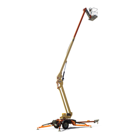
Page 28: Basic Nomenclature
2. Safety Chains (N/A on CE & Australian Spec) 3. Tongue Jack 4. Parking Brake 5. Outrigger 6. Chassis 7. Turntable 8. Lower Boom 9. Upright 10. Boom 11. Platform 12. Platform Console Figure 2-1. Basic Nomenclature – JLG Lift – 3121197... - Page 29 SECTION 2 - USER RESPONSIBILITIES, MACHINE PREPARATION, AND INSPECTION This page left blank intentionally. 3121197 – JLG Lift –...
-
Page 30: Daily Walk-Around Inspection - Sheet 1 Of 3
SECTION 2 - USER RESPONSIBILITIES, MACHINE PREPARATION, AND INSPECTION T350 Figure 2-2. Daily Walk-Around Inspection - Sheet 1 of 3 – JLG Lift – 3121197... -
Page 31: Daily Walk-Around Inspection - Sheet 2 Of 3
SECTION 2 - USER RESPONSIBILITIES, MACHINE PREPARATION, AND INSPECTION T500J Figure 2-3. Daily Walk-Around Inspection - Sheet 2 of 3 3121197 – JLG Lift –... -
Page 32: General
2. Platform & Ground Control Consoles - Switches and levers return to neutral, decals/placards secure and legi- ble, control markings legible. 3. Boom Sections/Turntable - See Inspection Note. Figure 2-4. Daily Walk-Around Inspection - Sheet 3 of 3 2-10 – JLG Lift – 3121197... -
Page 33: Section 3 - Towing
Platform/Ground Select switch to center OFF. Towing Hitch 5. Remove loose items from the platform. The towing hitch attached to your tow vehicle must have a capacity equal to or greater than the load rating of the trailer you 3121197 – JLG Lift –... -
Page 34: Tongue Height
All bent or broken coupler parts must be replaced before towing the trailer. – JLG Lift – 3121197... -
Page 35: Coupling The Trailer To The Hitch
4. Disconnect the safety chains from the tow vehicle. 7. Be sure the coupler is all the way on the hitch ball and the collar/locking mechanism is engaged. A properly engaged locking mechanism will allow the coupler to raise the rear of 3121197 – JLG Lift –... -
Page 36: Rigging Safety Chains (If Equipped)
This close to the road surface, so if the trailer uncouples, the would keep the breakaway brake system from operating safety chains can hold the tongue up above the road. when it is needed. – JLG Lift – 3121197... - Page 37 Store the battery indoors; and b. Charge the battery every three months. Reset the activation lever prior to towing. Replace the breakaway brake battery according to the intervals specified by the battery manufacturer. 3121197 – JLG Lift –...
-
Page 38: Connect The Electrical Cables
Brake Lights (Step on tow vehicle brake pedal). c. Turn Signals (Operate tow vehicle directional signal lever). d. Backup Lights (Put tow vehicle gear shift into reverse). Check electric brakes (if equipped) for proper operation. – JLG Lift – 3121197... -
Page 39: Engaging Manual Lockout Lever
• Be aware of the width of the trailer. This is important when turning, passing, and pulling next to a curb. • Be aware of the height of the trailer, especially when approaching roofed areas and around trees. LIFT LEVER TAB TO ENGAGE LOCKOUT 3121197 – JLG Lift –... - Page 40 The tires are not visibly low on pressure • Shift your automatic transmission into a lower gear for city driving. • Use lower gears for climbing and descending grades. • Do not ride the brakes while descending grades. – JLG Lift – 3121197...
-
Page 41: Pre-Tow Inspection
4. Tow Vehicle Coupler Ball (Not Shown) - Secured and in proper operating condition. Rock the hitch ball in all direc- tions to make sure it is tight to the hitch, and visually check 3121197 – JLG Lift –... -
Page 42: Pre-Tow Inspection - Sheet 1 Of 2
SECTION 3 - TOWING Figure 3-1. Pre-Tow Inspection - Sheet 1 of 2 3-10 – JLG Lift – 3121197... -
Page 43: Pre-Tow Inspection - Sheet 2 Of 2
SECTION 3 - TOWING Figure 3-2. Pre-Tow Inspection - Sheet 2 of 2 3121197 – JLG Lift – 3-11... - Page 44 SECTION 3 - TOWING NOTES: 3-12 – JLG Lift – 3121197...
-
Page 45: Section 4 - Machine Controls And Indicators
This indicator will be green with the exception of understand control functions. the capacity indicator which will be green or yellow depending upon platform position. CONTROLS AND INDICATORS NOTE: All machines are equipped with control panels that use symbols to indicate control functions. 3121197 – JLG Lift –... -
Page 46: Ground Control Station
When starting a cold engine, the choke switch must be Provides raising and lowering of the boom. pushed in (along with the engine start switch) until the 6. Jib Lift (if equipped) engine starts. Provides raising and lowering of the jib. – JLG Lift – 3121197... -
Page 47: Ground Control Station
4. Telescope 5. Lift 6. Jib Lift 7. Platform Level 8. System Distress 9. Outrigger Indicator 10. Outrigger Control 11. Swing 12. Function Enable 13. Platform Ground Select 14. Hourmeter Figure 4-1. Ground Control Station 3121197 – JLG Lift –... - Page 48 8. System Distress Indicator 12. Function Enable. The light indicates that the JLG Control System has detected The switch must be held to the right to enable all a malfunction and a Diagnostic Trouble Code has been set in boom controls.
-
Page 49: Platform Station
During this time the lights on the indicator panel will also blink once as a bulb check. 3121197 – JLG Lift –... - Page 50 2. Engine Choke (if equipped) 6. System Distress Indicator Engages engine choke. The light indicates that the JLG Control System has detected a malfunction and a Diagnostic Trouble Code has been set in 3. Function Selector the system memory. Refer to Section 5.8, User Fault Codes or...
-
Page 51: Platform Control Console - Standard Machine
5. Outrigger Set Indicator 6. System Distress Indicator 7. Battery Level Indicator 8. Tilt Alarm Warning Light 9. Function Enable 10. Not Used 11. Function Controller 12. Start Figure 4-2. Platform Control Console - Standard Machine 3121197 – JLG Lift –... -
Page 52: Platform Control Console W/Drive & Set Option
6. System Distress Indicator 7. Battery Level Indicator 8. Tilt Alarm Warning Light 9. Function Enable 10. Drive & Set /Outrigger Enable Button 11. Function Controller 12. Start Figure 4-3. Platform Control Console w/Drive & Set Option – JLG Lift – 3121197... - Page 53 Releasing the enable switch removes power from all con- ble alarm will sound. trols. 10. Drive & Set/Outrigger Enable Button Pushing the button enables the Drive & Set or Outrigger function depending upon the position of the Function Selector. 3121197 – JLG Lift –...
- Page 54 Controls boom functions (Platform Level, Lift, Swing, Jib Lift, To start the engine, the switch must be pushed in until the Telescope, Outriggers, Drive, and Steer) depending upon the engine starts. position of the Function Selector Switch. 4-10 – JLG Lift – 3121197...
-
Page 55: Section 5 - Machine Operation
4. All machine systems are functioning properly. The primary operator control station is in the platform. The oper- 5. Machine is as originally equipped from JLG. ator can raise or lower the main or tower boom or swing the boom to the left or right. Standard boom swing is 410° non-con- Stability tinuous left and right of the stowed position. -
Page 56: Position Of Least Forward Stability (T350)
TOWER RAISED ENOUGH TO GET MAIN BOOM TO HORI- ZONTAL MAIN BOOM FULLY EXTENDED AND HORIZONTAL TURNTABLE ROTATED MACHINE WILL TIP OVER IN 90 DEGREES FROM DIRECTION OF ARROWS IF OVERLOADED STOWED POSITION Figure 5-1. Position of Least Forward Stability (T350) – JLG Lift – 3121197... - Page 57 SECTION 5 - MACHINE OPERATION 3121197 – JLG Lift –...
-
Page 58: Position Of Least Forward Stability (T500J)
TOWER RAISED ENOUGH TO GET MAIN BOOM TO HORI- ZONTAL MAIN BOOM FULLY EXTENDED AND JIB HORIZONTAL HORIZONTAL TURNTABLE IN MACHINE WILL TIP OVER IN STOWED POSITION DIRECTION OF ARROWS IF OVERLOADED Figure 5-3. Position of Least Forward Stability (T500J) – JLG Lift – 3121197... - Page 59 SECTION 5 - MACHINE OPERATION 3121197 – JLG Lift –...
-
Page 60: Engine Operation (If Equipped)
When starting a cold engine, the choke switch must be pushed in (along with the engine start switch) until the engine starts. ALLOW ENGINE TO WARM-UP FOR A FEW MINUTES AT LOW SPEED BEFORE APPLYING ANY LOAD. – JLG Lift – 3121197... -
Page 61: Fuel Valve Lever
If the auto-level system does not operate properly, DO NOT operate the machine; have the system repaired by a qualified service technician. 3121197 – JLG Lift –... -
Page 62: From The Platform Console (Drive & Set Only)
2. To manually Level Down, turn and hold select switch to bas- ket level position, squeeze the enable switch and then move controller backward until desired position is reached. – JLG Lift – 3121197... -
Page 63: Swinging The Boom
2. To lower the boom select the Boom Control on the select switch, squeeze the enable switch and then move the con- troller backward. 3121197 – JLG Lift –... -
Page 64: Jib Lift
Function Problem - Swing Right Permanently Selected Function Problem - Telescope In Permanently Selected Function Problem - Telescope Out Permanently Selected Joystick Moved But Trigger Switch Open Trigger Closed Too Long While In Neutral 5-10 – JLG Lift – 3121197... - Page 65 Immediately return the platform to the stowed position and reposition the machine or reset the Drive Prevented - Lift Down outriggers, as required. If the problem still exists, troubleshoot with a JLG analyzer. Drive Prevented - Stow Outriggers Drive Prevented - Telescope In...
-
Page 66: Battery Charging
Connect the charger AC input plug to a grounded outlet. If the machine is equipped with an optional generator, the battery charger can be plugged into the generator outlet. See Figure 5-5. 5-12 – JLG Lift – 3121197... -
Page 67: Generator Plug Location
SECTION 5 - MACHINE OPERATION Figure 5-5. Generator Plug Location 3121197 – JLG Lift – 5-13... -
Page 68: Battery Charger Fault Codes
30 seconds of operation. Once it has been determined that the batteries and connections are not faulty and fault 6 is again displayed after inter- rupting AC power for at least 10 seconds, the charger must be brought to a qualified service depot. 5-14 – JLG Lift – 3121197... -
Page 69: Platform Removal & Installation
3. To install the platform, repeat steps 1 and 2 in reverse order. NOTE: The standard platform assembly weighs approximately 75 lbs. (34 kg). If equipped with the optional rotator, the platform assembly weighs approximately 150 lbs. (68 kg). 3121197 – JLG Lift – 5-15... -
Page 70: Material Hook Installation
1. Disconnect the platform control box harness at the platform support. 2. Remove the hitch pin and gravity pin securing the platform assembly to the platform support and remove the platform. 3. Remove the material hook from the storage position on the turntable. 5-16 – JLG Lift – 3121197... -
Page 71: Material Hook Operating Precautions
5. Secure the hook in place with the gravity pin and hitch pin. 5.13 MATERIAL HOOK OPERATING PRECAUTIONS When utilizing a JLG lift equipped with a material hook the fol- lowing additional precautions must be observed. The combined weight of material and rigging equipment must not exceed the maximum load capacity of the material hook. -
Page 72: Accessory Tray
WITH THE PANEL TRAY INSTALLED, THE ORIGINAL PLATFORM CAPACITY RATINGS ARE REDUCED AS SPECIFIED IN TABLE 7-1. DO NOT EXCEED THE NEW PLATFORM CAPACITY RATING. REFER TO THE CAPACITY DECAL LOCATED IN THE TRAY. 5-18 – JLG Lift – 3121197... -
Page 73: Panel Tray
SECTION 5 - MACHINE OPERATION 1. Strap 2. Capacity Decal 3. Nameplate 4. Left Tray Panel 5. Clamp 6. Pad 7. Right Tray Panel Figure 5-6. Panel Tray 3121197 – JLG Lift – 5-19... -
Page 74: Drive & Set
1. Place the boom in the stowed position (fully retracted, fully lowered, over the trailer tongue). 2. Set the parking brake (ANSI brake shown). Refer to the park- ing brake decal on the tongue. 3. Release the boom latch. 5-20 – JLG Lift – 3121197... - Page 75 SECTION 5 - MACHINE OPERATION 3121197 – JLG Lift – 5-21...
-
Page 76: Grade And Sideslope
SECTION 5 - MACHINE OPERATION SIDESLOPE GRADE ANSI/CSA/AUS SIDESLOPE - 11° ANSI/CSA/AUS GRADE - 20% LEVEL CE SIDESLOPE - 8.5° CE GRADE - 15% Figure 5-7. Grade and Sideslope 5-22 – JLG Lift – 3121197... -
Page 77: To Prepare The Machine For Towing After Drive & Set
7. Properly enter the platform and start the engine. 2. Stow the outriggers. 8. Turn the function selector switch in the platform to the Drive 3. Drive the machine to a firm, level, and smooth surface. position. 3121197 – JLG Lift – 5-23... - Page 78 5. Remove the pin securing the jockey wheel in the drive posi- jockey wheel off of the ground. tion and swing the wheel up into the stowed position. Secure the wheel in place with the retaining pin. 5-24 – JLG Lift – 3121197...
- Page 79 SECTION 5 - MACHINE OPERATION 3121197 – JLG Lift – 5-25...
-
Page 80: Shut Down And Park
5. If necessary, cover Platform Controls to protect instruction placards, warning decals and operating controls from hostile environment. 6. Set parking brake and uncouple from towing vehicle. 7. The machine is now ready for towing. Refer to Section 3, TOWING. 5-26 – JLG Lift – 3121197... -
Page 81: Tie Down
Figure 5-9.) 2. Remove all loose items from the machine. 3. Secure the chassis and the platform using straps or chains of adequate strength and attached to the designated tie down points. (See Figure 5-9.) 3121197 – JLG Lift – 5-27... -
Page 82: Lifting And Tie Down Chart Prior To S/N 0030000864
SECTION 5 - MACHINE OPERATION Figure 5-8. Lifting and Tie Down Chart Prior to S/N 0030000864 5-28 – JLG Lift – 3121197... -
Page 83: Lifting And Tie Down Chart S/N 0030000864 To
SECTION 5 - MACHINE OPERATION Figure 5-9. Lifting and Tie Down Chart S/N 0030000864 to Present 3121197 – JLG Lift – 5-29... -
Page 84: Decal Location - Ansi (Sheet 1 Of 2)
SECTION 5 - MACHINE OPERATION Figure 5-10. Decal Location - ANSI (Sheet 1 of 2) 5-30 – JLG Lift – 3121197... -
Page 85: Decal Location - Ansi (Sheet 2 Of 2)
SECTION 5 - MACHINE OPERATION Figure 5-11. Decal Location - ANSI (Sheet 2 of 2) 3121197 – JLG Lift – 5-31... -
Page 86: Decal Legend (Ansi)
Table 5-2. (Continued)Decal Legend (ANSI) Table 5-2. Decal Legend (ANSI) 0274522-L Item # Item # 0274522-L 1706106 1706107 1701640 1001119637 1703814 1706121 - T350 1706384 1706264 - T500J 1703817 1706127 1704277 1706133 w/Drive 1704412 1706139 1706629 1706263 1706372 1706385 1706112 1001131269... - Page 87 SECTION 5 - MACHINE OPERATION Table 5-2. (Continued)Decal Legend (ANSI) 0274522-L Item # 37 to 38 1706337 1706349 1706440 3251813 3760170 3820001 3820032 8990147 1705817 1702773 1705304 3121197 – JLG Lift – 5-33...
-
Page 88: Decal Location - Ce & Australia (Sheet 1 Of 2)
SECTION 5 - MACHINE OPERATION Figure 5-12. Decal Location - CE & Australia (Sheet 1 of 2) 5-34 – JLG Lift – 3121197... -
Page 89: Decal Location - Ce & Australia (Sheet 2 Of 2)
SECTION 5 - MACHINE OPERATION Figure 5-13. Decal Location - CE & Australia (Sheet 2 of 2) 3121197 – JLG Lift – 5-35... -
Page 90: Decal Legend - Ce & Australia
SECTION 5 - MACHINE OPERATION Table 5-3. Decal Legend - CE & Australia (Continued) Table 5-3. Decal Legend - CE & Australia 0273631-H Item # Item # 0273631-H 1706121 - T350 1706264 - T500J 1701640 1706139 1703814 1706314 1706384 1706263 1703817... - Page 91 SECTION 5 - MACHINE OPERATION Table 5-3. Decal Legend - CE & Australia (Continued) 0273631-H Item # 4420051 3121197 – JLG Lift – 5-37...
-
Page 92: Decal Location - Country Specs (Sheet 1 Of 2)
SECTION 5 - MACHINE OPERATION Figure 5-14. Decal Location - Country Specs (Sheet 1 of 2) 5-38 – JLG Lift – 3121197... -
Page 93: Decal Location - Country Specs (Sheet 2 Of 2)
SECTION 5 - MACHINE OPERATION Figure 5-15. Decal Location - Country Specs (Sheet 2 of 2) 3121197 – JLG Lift – 5-39... -
Page 94: Decal Legend - Country Specs
1704277 1704277 1704277 1704277 1704412 1704412 1704412 1704412 1706629 1706629 1706629 1706629 1706372 1706372 1706372 1706372 1706385 1706385 1706385 1706385 0701014 0701014 0701014 0701014 1001131269 1700584 1700584 1700584 1701644 1701644 1701644 1701644 1702155 1705304 5-40 – JLG Lift – 3121197... - Page 95 0273641-H 0273644-H 0273640-H 0274942-E 1705754 1705754 1705754 1705754 1706080 - T350 1706080 - T350 1706080 - T350 1706080 - T350 1706081 - T500J 1706081 - T500J 1706081 - T500J 1706081 - T500J 1706106 1706106 1706106 1706106 1706107 1706107 1706107 1706107...
- Page 96 1703813 1706139 1706139 1706139 1706139 1706337 1706337 1706337 1706337 1706349 1706349 1706349 1706349 1706440 1706440 1706440 1706440 W/O Drive 0274819 0274830 0274832 Option: With Drive 0274828 0274831 0274833 Option: 3251243 3251243 1706513 1706524 1706427 5-42 – JLG Lift – 3121197...
- Page 97 1706527 1706430 1706517 1706528 1706431 1706518 1706529 1706432 1706519 1706530 1706433 1706520 1706531 1706434 1706521 1706532 1706435 1706522 1706533 1706436 1706523 1706534 1706437 1706565 1706657 1706664 1706569 1706658 1706665 1703864 1703832 1703840 3251813 3251813 3121197 – JLG Lift – 5-43...
- Page 98 Table 5-4. Decal Legend - Country Specs ANSI Export ANSI Export ANSI Export ANSI Export Item # French/English Portuguese/English Spanish/English S. Africa 0273641-H 0273644-H 0273640-H 0274942-E 1705817 1705817 1705817 1702773 1706351 1706496 1706494 1706495 5-44 – JLG Lift – 3121197...
-
Page 99: Section 6 - Emergency Procedures
BEEN REPAIRED, IF REQUIRED, AND THAT ALL CONTROLS ARE OPERATING COR- RECTLY. JLG Industries, Inc. must be notified immediately of any incident involving a JLG product. Even if no injury or property damage is EMERGENCY OPERATION evident, the factory should be contacted by telephone and pro- vided with all necessary details. -
Page 100: Platform Or Boom Caught Overhead
MANUAL DESCENT The manual descent system is provided as an emergency means to lower personnel from the platform. NOTE: The main valve cover must be removed to access Lift and Tele- scope manual controls. – JLG Lift – 3121197... -
Page 101: Lift Down
LOWER RAPIDLY. plate. 4. The boom will descend by itself. To stop the boom from descending, release the button on the valve with the rubber boot. 3121197 – JLG Lift –... -
Page 102: Telescope In
Pull out on the small button and hold. Using the handle, work the Rotate the button clockwise, push in and hold. Using the handle, hand pump. The boom will retract with each stroke. work the hand pump. The boom will extend with each stroke. – JLG Lift – 3121197... -
Page 103: Swing
Install the wrench on the nut and Turn slowly counterclockwise to lower the Jib. After this opera- ratchet in the desired direction. tion has been completed, turn the knob clockwise until tight. 3121197 – JLG Lift –... - Page 104 SECTION 6 - EMERGENCY PROCEDURES NOTES: – JLG Lift – 3121197...
-
Page 105: Section 7 - General Specifications & Operator Maintenance
Maximum Work Load (Capacity) 500 lbs. 500 lbs. T350 Service and Maintenance Manual ........3121198 w/o Rotator (227 kg) (227 kg) T500J Service and Maintenance Manual ........3121200 Maximum Work Load (Capacity) 320 lbs. 320 lbs. w/Rotator & Panel Tray (145 kg) (145 kg) T350 &... - Page 106 30.7 psi (1.58 kg/cm (2.15 kg/cm Maximum Travel Gradeability - ANSI, CSA, AUS (see Figure 5-7.) Maximum Travel Gradeability - CE (see Figure 5-7.) Maximum Sideslope - ANSI, CSA, AUS 11° 11° (see Figure 5-7.) – JLG Lift – 3121197...
-
Page 107: Dimensional Data
Voltage 24 VDC 24 VDC 24 VDC Amperage Speed 4000 rpm 3600 rpm 2900 rpm Pump Flow Rate 3.0 gpm 2.7 gpm 2.2 gpm (11.3 lpm) (10.2 lpm) (8.3 lpm) Displacement 0.192 cu.in. (3.15 cc) 3121197 – JLG Lift –... -
Page 108: Taillight And Marker Light Bulb Information
Taillight (Single Contact) - CE/Aus Wheel Nut 90-120 ft. lbs. 66 ft. lbs. 90-120 ft. lbs. 221 ft. lbs. (300 Torque (122-164 Nm) (90 Nm) (122-164 Nm) Foglight - CE 7000093 License Plate Light - CE/Aus 7000096 – JLG Lift – 3121197... -
Page 109: Engine
0.028 - 0.031 in. (0.70 - 0.80 mm) Table 7-8. Engine Battery Specifications BCI Group Size Cranking Performance 550 amps @ 32°F (0°C) 450 amps @ 0°F (-18°C) Reserve Capacity 80 minutes @ 32°F (0°C) 3121197 – JLG Lift –... -
Page 110: Component Weights
SECTION 7 - GENERAL SPECIFICATIONS & OPERATOR MAINTENANCE Component Weights Table 7-11. Component Weights - T500J Table 7-10. Component Weights - T350 Component Pounds Kilograms Frame (bare) Component Pounds (Kg) Kilograms Frame - CE, Aus (bare) Frame (bare) Turntable (bare) Turntable (bare) Booms &... -
Page 111: Lubrication
SECTION 7 - GENERAL SPECIFICATIONS & OPERATOR MAINTENANCE Lubrication Aside from JLG recommendations, it is not advisable to mix oils of differ- ent brands or types, as they may not contain the same required addi- HYDRAULIC OIL tives or be of comparable viscosities. If use of hydraulic oil other than Mobilfluid 424 is desired, contact JLG Industries for proper recommenda- Table 7-12. -
Page 112: Operator Maintenance & Lubrication Diagram
6. Swing Drive 10. Surge Brake 3. Hydraulic Filter & Breather 7. Engine 11. Coupler & Hitch Ball 4. Swing Bearing 8. Fuel Tank 12. Jockey Wheel Bearing Figure 7-1. Operator Maintenance & Lubrication Diagram – JLG Lift – 3121197... -
Page 113: Operator Maintenance
Interval - every 12 months or 12,000 miles Engine (crankcase) Oil. Gas - API SF/SG class, MIL-L-2104. Diesel - API Comments - Refer to the Service Manual for procedure CC/CD class, MIL-L-2104B/MIL-L-2104C. Open Gear Lubricant - Mobiltac 375 or equivalent. 3121197 – JLG Lift –... - Page 114 Capacity - 4 gal. (15.1 L) Lube - HO Interval - Check oil daily, change after every 1200 hours of operation. Interval - 100 hours Comments - Change after the first 20 hours, then every 100 hours of operation. 7-10 – JLG Lift – 3121197...
- Page 115 DO NOT OVERGREASE BEARINGS. OVERGREASING BEARINGS WILL RESULT IN BLOW- Lube Point(s) - Spray On ING OUTER SEALS IN HOUSING. Capacity - As Required Lube - OGL Interval - Every month or 50 hours Comments - More frequent lubrication intervals may be required. 3121197 – JLG Lift – 7-11...
- Page 116 Lube - EO, 10W30 API SJ Fuel - Gasoline Interval - Check level daily; change per Interval - Check periodically during each shift manufacturer’s engine manual. Comments - Adjust final oil level by mark on dipstick 7-12 – JLG Lift – 3121197...
- Page 117 (13 mm) from top of reservoir Interval - As necessary " Lube - DOT 3 or 4 Brake Fluid Interval - Check before each tow. Flush the system yearly or when system is known to be contaminated 3121197 – JLG Lift – 7-13...
- Page 118 Capacity - Coupler 2 Grease Fittings (CE Only); Hitch Ball As necessary Lube - MPG Lube Point(s) - 1 Grease Fittings Interval - As necessary Capacity - As Required Lube - MPG Interval - As Required 7-14 – JLG Lift – 3121197...
-
Page 119: Tires & Wheels
VIN label. Actual weight determined by weighing trailer on a scale, without being attached to the towing vehicle. Maximum Permissible Inflation Pressure - The maximum cold inflation pressure to which a tire may be inflated. 3121197 – JLG Lift – 7-15... -
Page 120: Tire Inflation
The following tire wear diagnostic chart will help you pinpoint must measure tire pressure when the tires are cold or compensate the causes and solution of tire wear problems. for the extra pressure in warm tires. 7-16 – JLG Lift – 3121197... -
Page 121: Tire Repair
A replacement tire must be the same size, ply rating and load Section 7 range as originally installed on the trailer. Please refer to the JLG Parts Manual for the part number of the Cupping Out of balance Check bearing approved tires for a particular machine model. - Page 122 SECTION 7 - GENERAL SPECIFICATIONS & OPERATOR MAINTENANCE Figure 7-2. Information on Tires - Sheet 1 of 2 7-18 – JLG Lift – 3121197...
- Page 123 Tire manufacturers also diameter. must indicate the materials in the tire, which include steel, nylon, polyester, and others.. Figure 7-3. Information on Tires - Sheet 2 of 2 3121197 – JLG Lift – 7-19...
-
Page 124: Wheel Replacement
Tighten the lug nuts to the proper torque for the axle size on your trailer, to prevent wheels from coming loose. Use a torque wrench to tighten the fasteners. If you do not have a torque 7-20 – JLG Lift – 3121197... -
Page 125: Lug Nuts (Bolts)
METAL CREEP BETWEEN THE WHEEL RIM AND LUG NUTS WILL RESULT IN A WHEEL (20) (50) (90) COMING OFF, LEADING TO DEATH OR SERIOUS INJURY. TIGHTEN LUG NUTS BEFORE Table 7-18. Wheel Torque Chart - T500J CE EACH TOW. TORQUE SEQUENCE -ft lbs (Nm) 1st Stage 2nd Stage... -
Page 126: Unsealed Wheel Bearings (Hubs)
The vibration total value to which the hand-arm system is sub- jected does not exceed 2,5 m/s . The highest root mean square value of weighted acceleration to which the whole body is sub- jected does not exceed 0,5 m/s 7-22 – JLG Lift – 3121197... -
Page 127: Section 8. Inspection And Repair Log
SECTION 8 - INSPECTION AND REPAIR LOG SECTION 8. INSPECTION AND REPAIR LOG Machine Serial Number _______________________________________ Table 8-1. Inspection and Repair Log Date Comments 3121197 – JLG Lift –... - Page 128 SECTION 8 - INSPECTION AND REPAIR LOG Table 8-1. Inspection and Repair Log Date Comments – JLG Lift – 3121197...
- Page 132 1 JLG Drive McConnellsburg PA. 17233-9533 (717) 485-5161 3121197 (717) 485-6417 JLG Worldwide Locations JLG Industries (Australia) JLG Latino Americana Ltda. JLG Industries (UK) Ltd JLG France SAS P.O. Box 5119 Rua Eng. Carlos Stevenson, Bentley House Z.I. de Baulieu...
Need help?
Do you have a question about the T500J and is the answer not in the manual?
Questions and answers
Lift Bucket stuck in the air and will not come down
The JLG T500J lift bucket may be stuck in the air and not coming down due to a short in the Tan 3-2 or Tan 3-2-1 wire, a mechanically stuck or electrically shorted "Lift Up" switch, or a power module failure including issues with power wiring or a shorted MOSFET. These faults can cause the "Lift Up" function to remain permanently selected, preventing descent.
This answer is automatically generated
How long does it take to charge a T500J lift?